Feels like no discussion of this would be complete without linking to Billie Ruben’s infographic from a few years ago. I think technology has improved a good bit in the past three years, softening some of the recommendations, but anyone who hasn’t seen it yet will probably benefit from reading it:
Now on to my own learnings! 
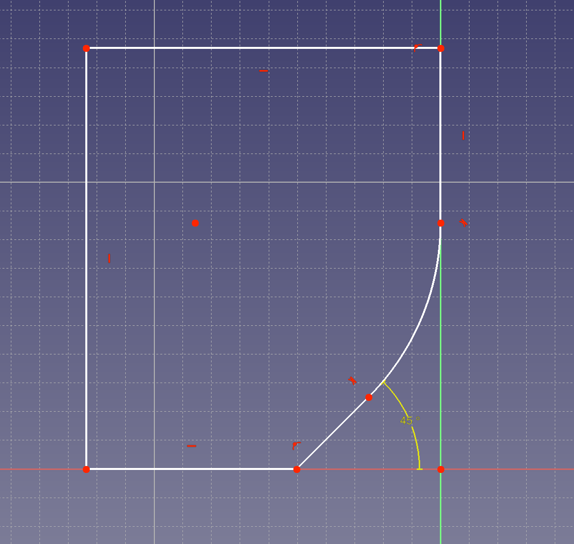
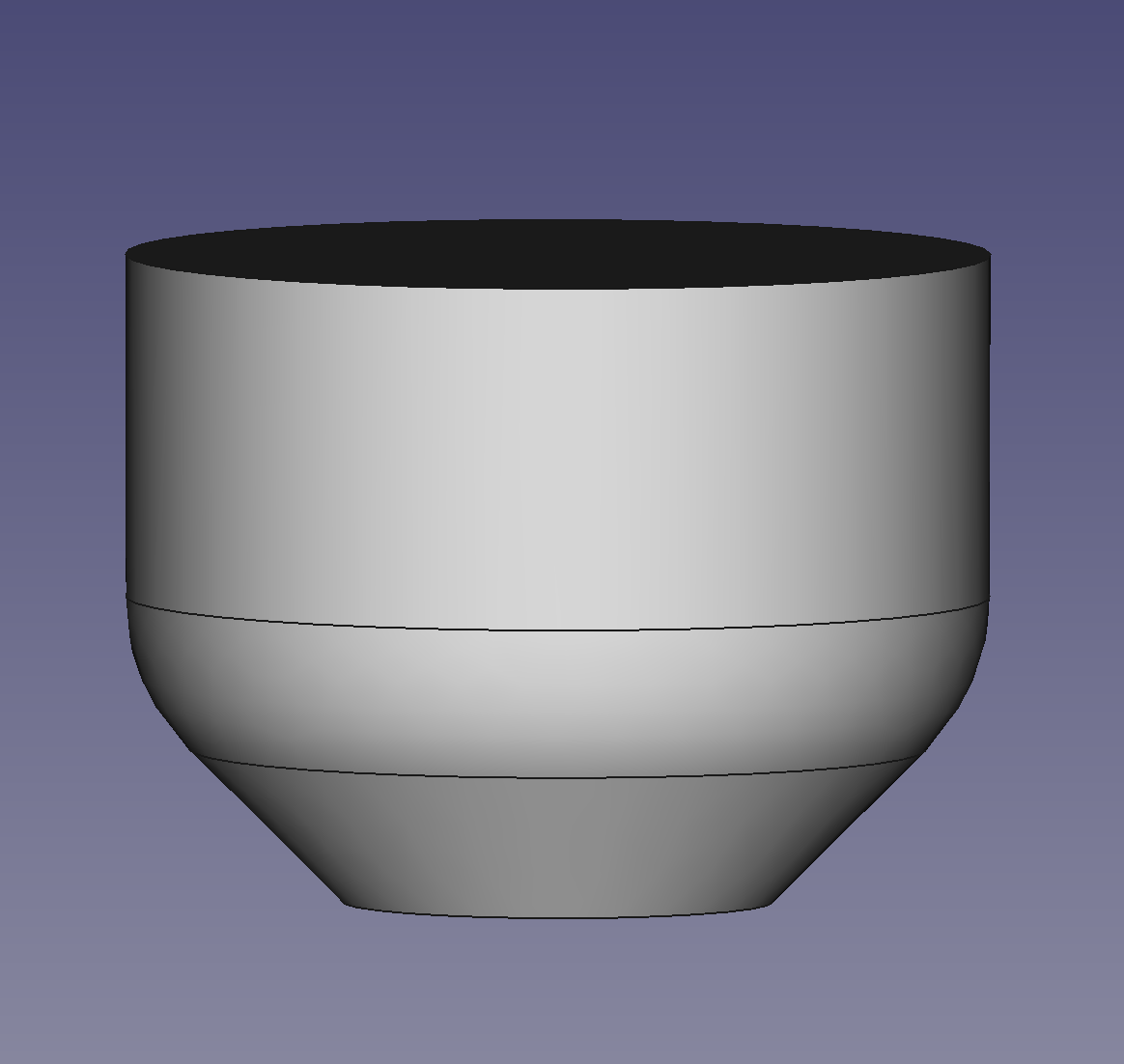
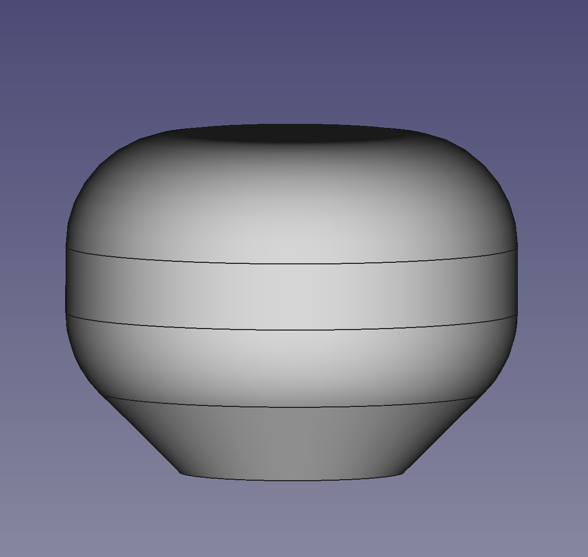
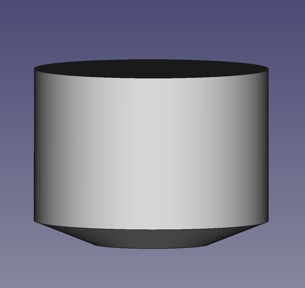
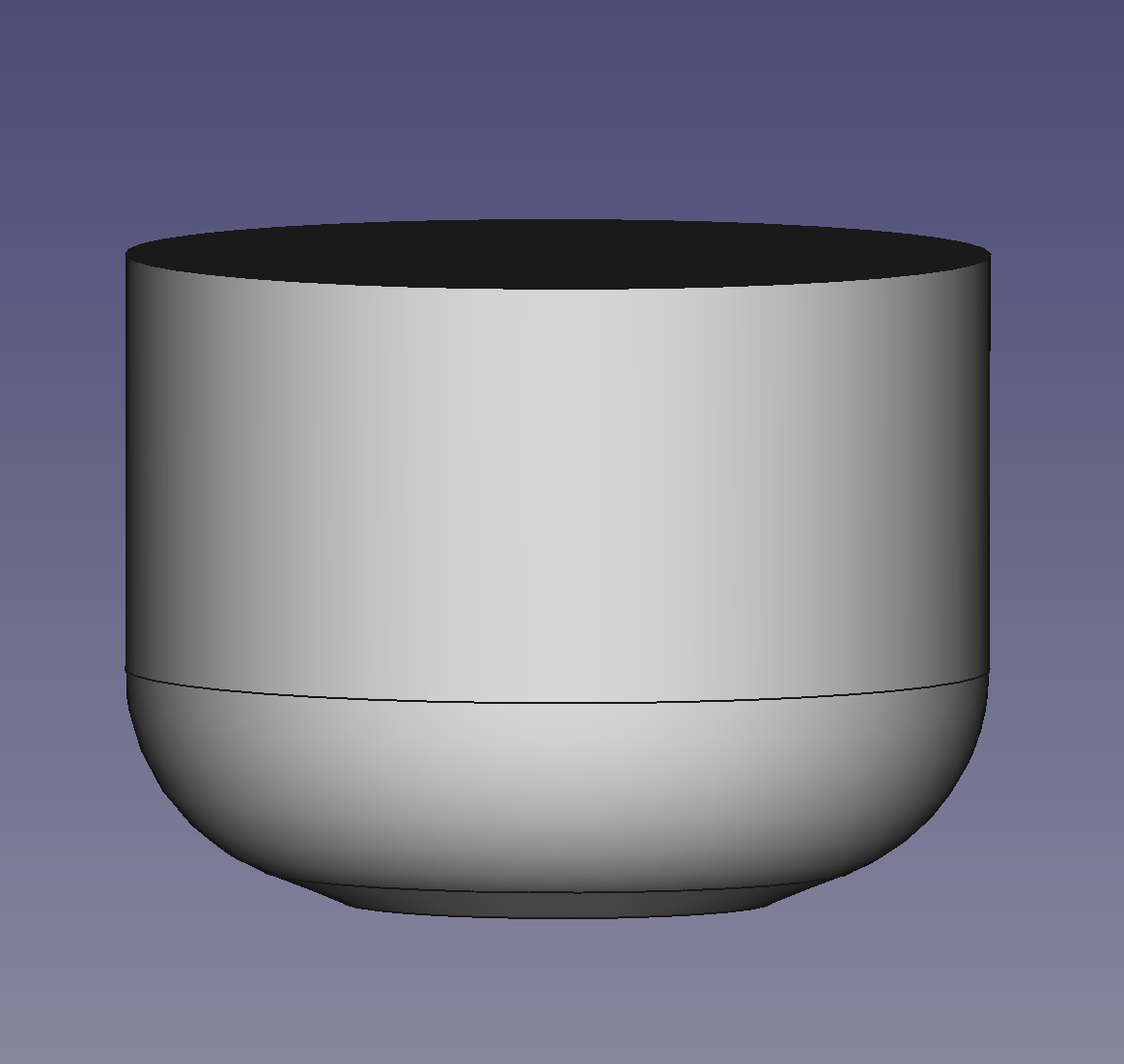
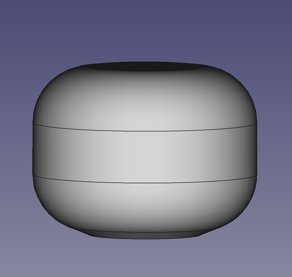
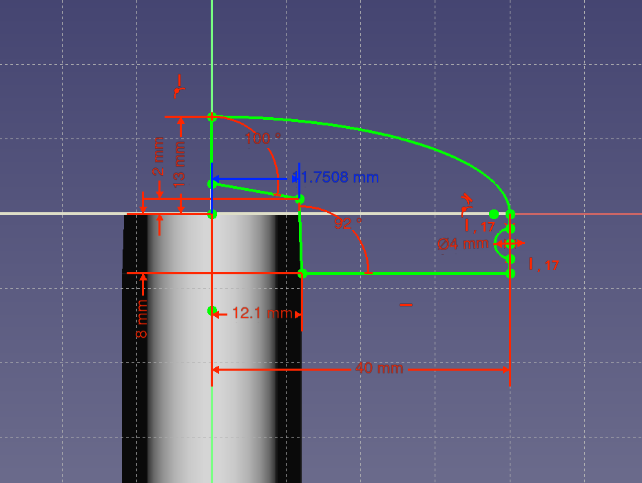
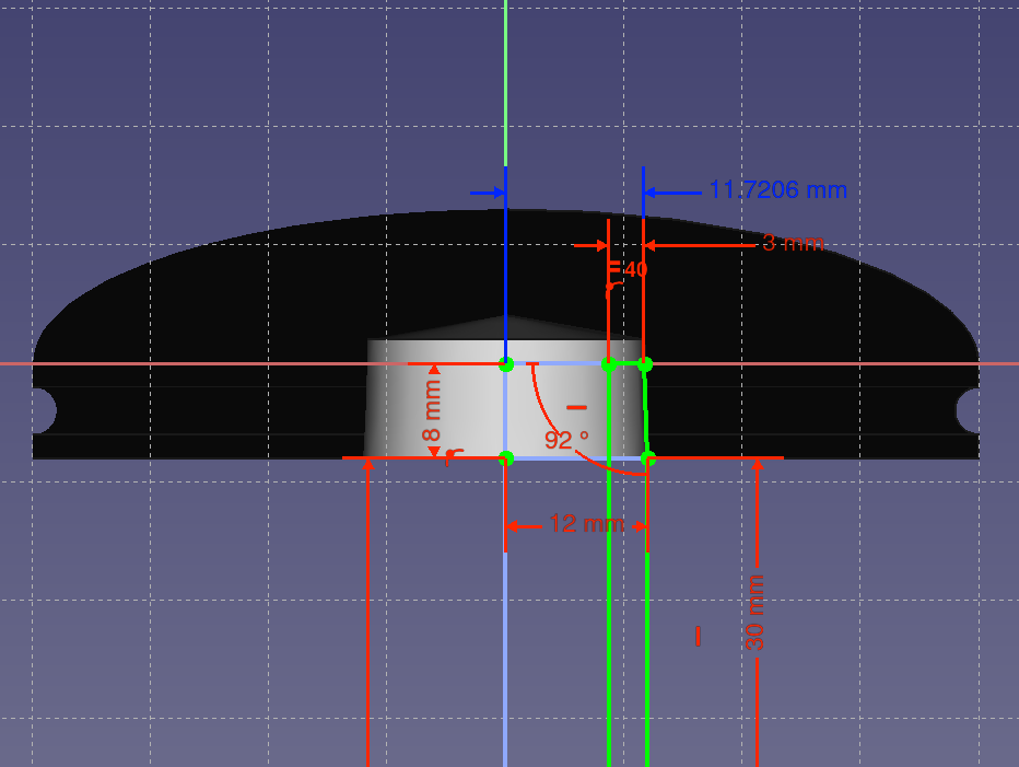
As Billie Ruben points out, you can approximate downward-facing fillets and make them more printable by making them tangent to a 45° chamfer.
However, depending on the printer and filament, you can get away with a much smaller angle. For example, printing ABS on my current primary printer, I can get away with a 10° angle for a substantial distance. With a two-offset chamfer, making the long horizontal measurement just 1mm larger than the radius of the attached chamfer may be sufficient to turn a downward-facing fillet from a skirt of loosely-adhered spaghetti near the bed to a nice smooth surface.
Especially on modern printers with capable, high-volume extruders, smooth large perimeters are time-cheap. Sharp corners slow down printing. Fillets don’t just look nice, they can speed the print up, and can make prints substantially stronger. The same amount of plastic, or maybe even less, can be stronger by taking a “short cut” rounding what would otherwise be a square corner.
Particularly when repairing something by designing and printing a replacement part, take advantage of the characteristics of 3d printing. For example, a neighborhood friend asked me to print a part for a pocket router. He had found an STL that reproduced everything about the part, including the aspects that were designed for it being injection molded. This meant that it would have to be printed with supports in any orientation.
I learned how it would be used, and was able to remove unnecessary features to make it have a flat side for printing, which also made it more robust. I believe it has now lasted longer than the original.
Similarly, when designing functional parts from scratch, design for 3d printing characteristics. For example, think about the best direction for layers, both for printability and for key loads when the part is in use. We have a lot of experience of relatively homogeneous materials (most metals and plastics we experience day to day) so it’s easy to forget how anisotrophic 3d prints are. I think of 3d prints more like wood, where if you are designing with wood you typically have to think a lot about grain direction.
Finally: Before throwing out failures or prototypes, break them while paying close attention. See, hear, and feel how they break. Build up your intuition for how parts fail by making them fail and watching how they do it. Where you can safely do this with your hands, you will probably gain most intuition from feeling how it breaks. (Maybe wear gloves; I cut myself last time I did this.) But where you can’t do it with your hands, use tools, with appropriate protection, especially eye protection! I’ve used various sorts of pliers, vise grips, side cutters, hammers, chisels, and even once a hydraulic press to better understand failure modes intuitively. After doing this enough, I can look at a design and imagine a possible failure mode, and feel how the part is likely to break. Some sort of intuitive wetware FEA I guess.  Just keep in mind that plastic can fracture into sharp pieces and some of them can go flying, so I’m not kidding about using appropriate personal protective equipment.