After Reverse engineering a 3d printing gear model I decided to start from scratch. I built a FreeCAD model that uses embedded parameters in gears to make it possible to print the sets of gears that you want, and I generated a set of gears that my wife (the mathematician for whom I did this work) asked for to teach a workshop.

I’m able to stuff all three rings and seven gears that my wife chose on my printer for a single print:
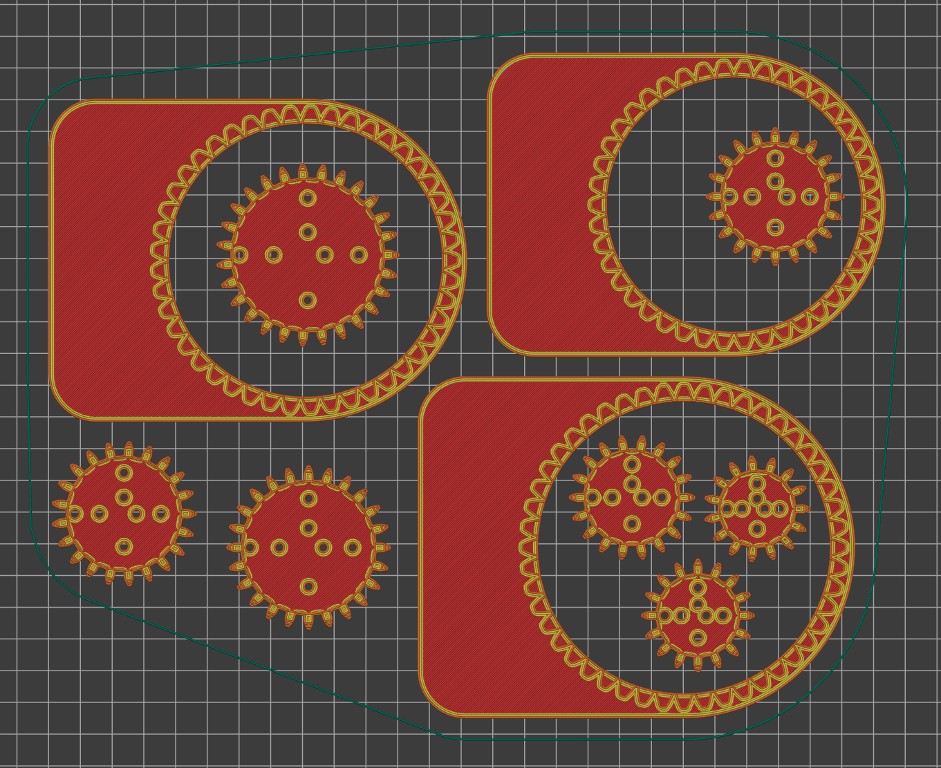
This is good because the print takes 3 hours and I’m going to be making six sets this weekend. ![]()
The OBJ files are printable as provided. Choose slicer settings for high quality; artifacts from roughness on the teeth will make the set work poorly and/or be visible in the drawings.
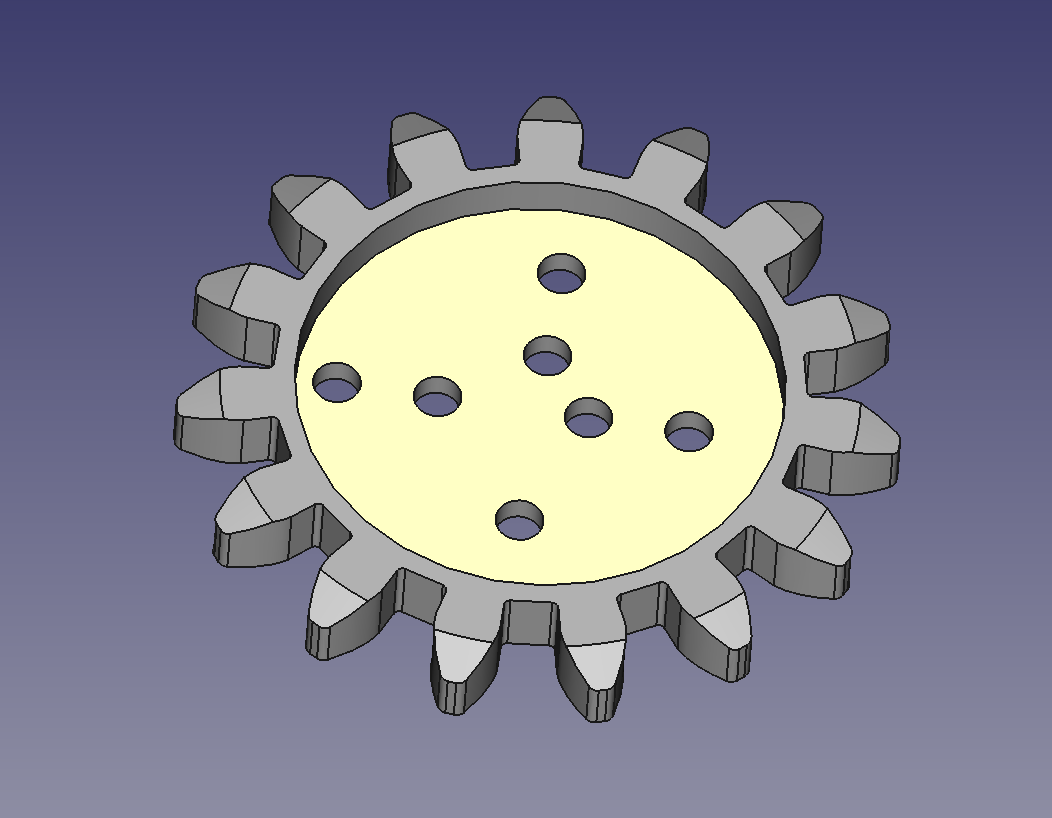
To use, flip the rings over, so that the flange is above the teeth. The flange helps hold the teeth of the gears down so they don’t jump out.
The gears are used as printed. The upper tips of the gears are chamfered to keep them from catching on the flange.
The racetrack on the ring is to assist gripping the ring solidly to hold it in place during use.
If you want to make other size rings and gears, the FCStd files were created with FreeCAD 0.20.1 and the FCGear workbench. You will need the FCGear Workbench installed to make modifications.
In FreeCAD, select the gray InvoluteGear in the Gear, or the gray InternalInvoluteGear in the Ring, and then change the base property teeth to the number of teeth you want. (If you want a Gear with fewer than 15 teeth, you might need to edit the Drawing Holes Pocket sketch and delete (or change to construction geometry) some holes that collide.)
If you would like larger teeth (and, naturally the resulting size), change the base property module from 2mm to 3mm for both the Ring and the Gear and regenerate all the rings and gears you wish to use.
All the files, both the ten OBJ files and the two FCStd files, are available at GitLab: