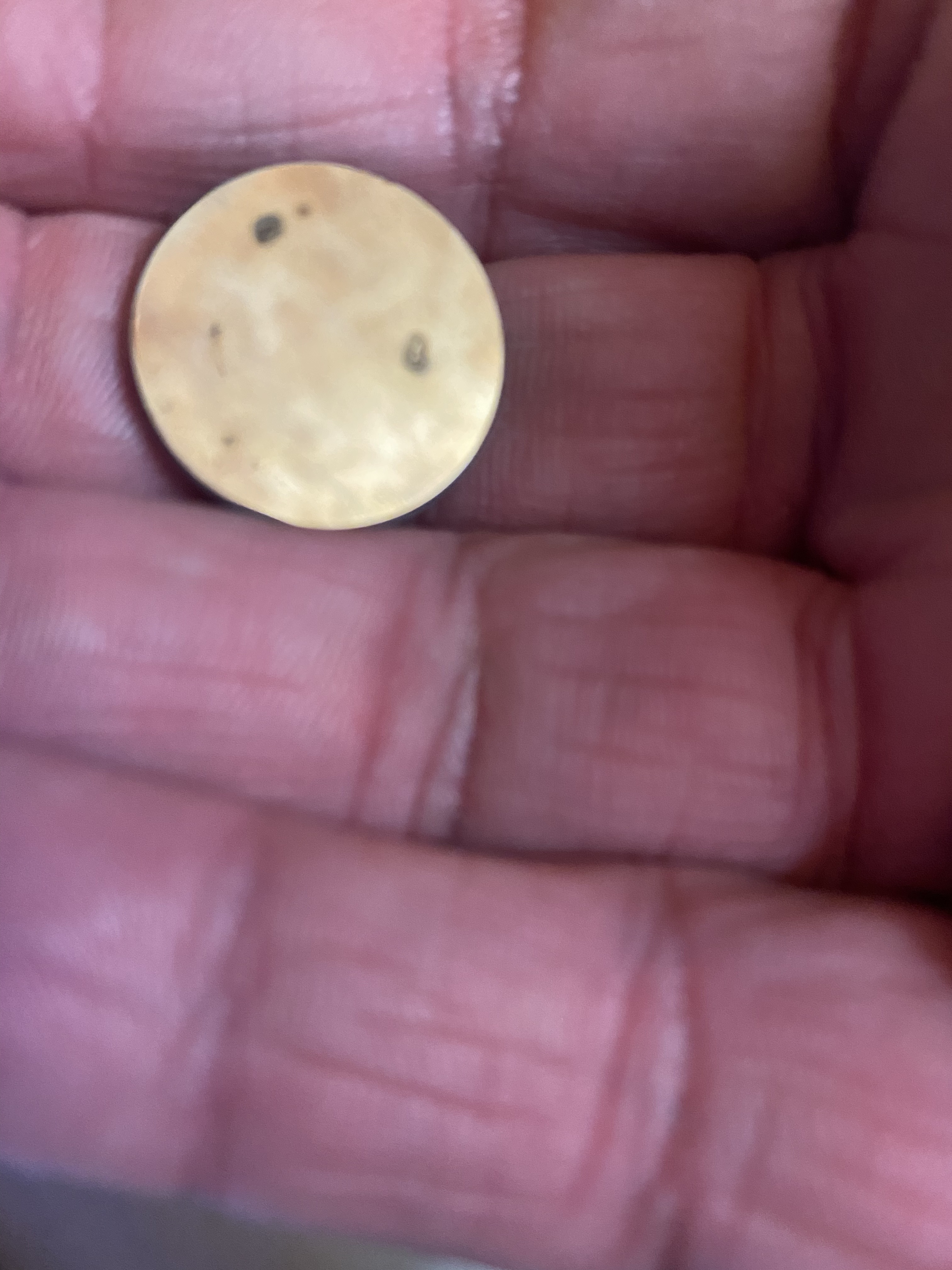
That one looks great. Was it in the same location on the bed?
Your % reading on the digital panel may not be the same as before with this new laser. However 15% change does seem like alot.
I found Slate to be pretty unpredictable as the material is irregular and varies in thickness and roughness
To test I would engrave on something more predictable.
Run the same job 4x with the material positioned in one of 4 quadrants.
Run it a minimal power setting such that it just barely showing all of the images. This will enable you to see small changes in power at differing locations on the bed.
yeah, the above one was @ 30% at the same location. It seems weird that it turned out so well and the others were faded. I understand a different tube may have a completely different output as well but I’d figured the new one would have been better than the original
I suppose like when I originally got it, there is going to be quite a lot of playing, experimenting and wastage!! Looks like all the settings I had for the slates before will need to be revisited
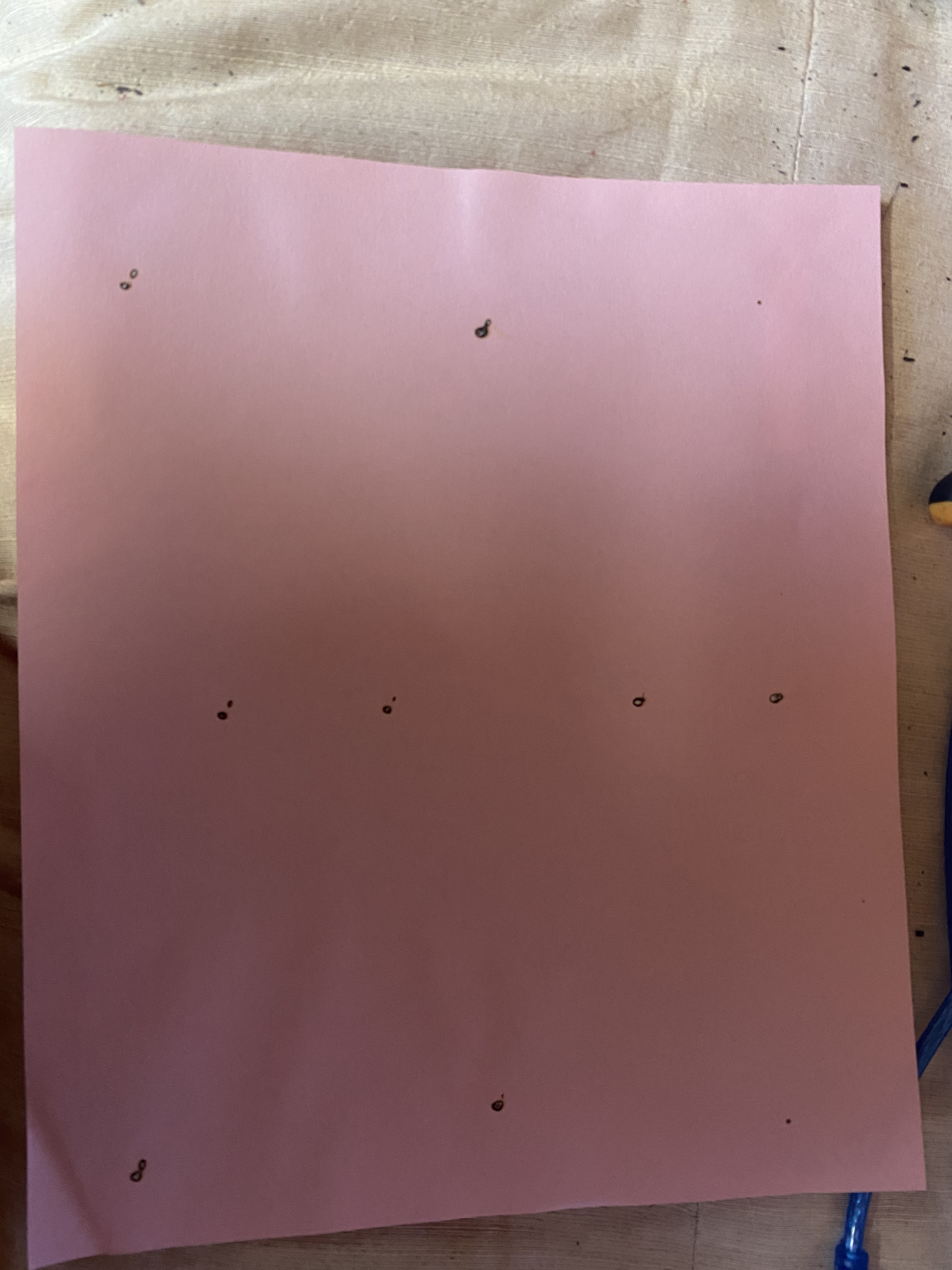
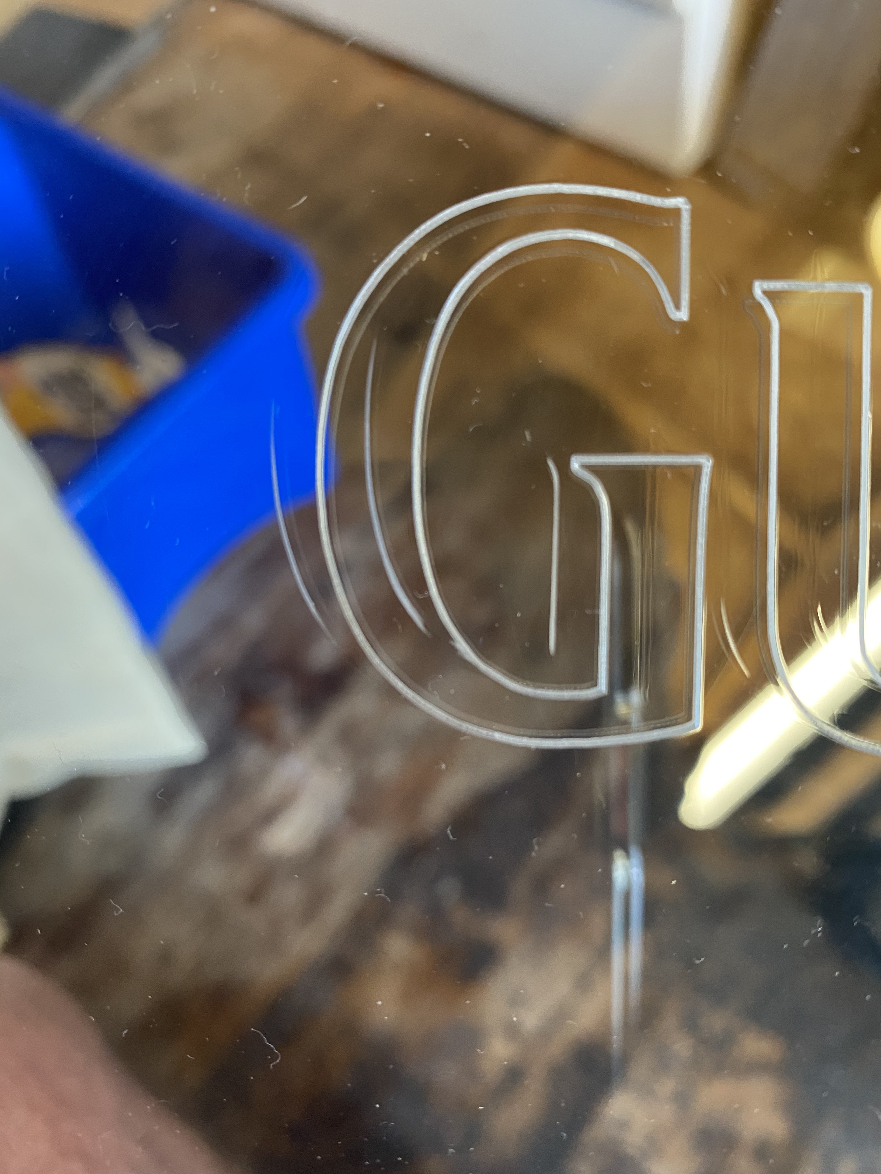
Back to alignment again folks. The attached pics show that along the bottom of the cutting bed (30x20cm) the laser seems to be splitting into 2 beams. The pink paper seems to have attached as landscape so the bottom is actually along the left side of the attached pic. I did this with the bottom of the laser head off. The effects of this are in the 2nd pic when I vector engrave letters. You will notice the ‘G’ has defective lines which I am assuming is due to the beam being split? Any suggestions? It also seems that along the bottom of the bed (more so toward the bottom right) that the raster effect fades considerably.
So what you’re saying maybe is to look at the alignment again possibly as this split is only happening in certain areas? Splitting anywhere ‘could’ be as a result of misalignment? It is also a new tube but I do understand that means nothing either The beam firing onto mirror 3 is a LITTLE low of centre so maybe I need to raise the tube a tiny bit and realign all over again?
If the beam pattern looks right using witness paper in front of the first mirror, then it’s unlikely to be in a higher TEM. I’d suggest taking pictures of witness paper before mirror 1, before mirror 2, before the head mirror, at the bottom of the tube with the lens removed, and at the bottom of the tube with the lens installed, and post those pictures here at high resolution and carefully labeled.
My guess is that your tube is not parallel to the gantry and is pointing uphill or downhill.
Its common to have this problem with a new laser install.
It’s hard to see what is wrong unless you target at 2 places along the beam path and between mirrors.
Thanks again - this is going on much longer than even I anticipated so thanks for your patience!!
I played about again with alignment and seem to have fixed the splitting problem. But the fading toward the right bottom still remains a factor. From what I am seeing, the beam hits to the centre of mirror 1, then also to the centre of 2 & 3. I took out mirror 3 and it doesn’t look to healthy but that wouldn’t explain the fading though?
yeah, I think I’ll get some new mirrors (at least to replace mirror 3) to see what (if any) difference that makes!! It just dawned on me earlier to check it
yeah, let me get a set of mirrors and see what happens then? They come on different diameters. I’m assuming the basic K40 machines are 19mm/20mm?
These seem to have the best reviews


 The beam firing onto mirror 3 is a LITTLE low of centre so maybe I need to raise the tube a tiny bit and realign all over again?