If your tube already has a wire attached I would recommend these connectors.
2 Likes
this is what I see available in the uk
I think you don’t want the connectors already connected though.
If you can’t get the plain connectors that @NedMan linked to, I’d suggest the “twist and seal with silicone tubing and sealant” option. You can leave a bit of extra wire and order some of those plain connectors to attach the next time you open the box.
2 Likes
The best advice I can give:
Take a photo of how the tube currently sits (how close to mirror 1 and how highly) this will make mirror alignment easier.
If your machine doesn’t currently have a high voltage connector, get one. It’ll save you time and give you peace of mind. It’ll make future tube changes easier too.
Don’t think about it too much, I’d never done it before and managed to swap it out in 10 minutes, it’s been running great ever since. Feel free to message me if you have any questions
4 Likes
can’t seem to find the right high voltage connectors on Amazon UK. Any advice on the right one? And yes @renegadeltd I am probably thinking too much about it. Probably will continue to until the tube arrives in a few days 
I got mine from eBay - grey goose I think the company is called. They are the company that are the distributors for mini grbl board
3 Likes
That’s a very kind offer! May I request at-mentioning in this thread instead of messaging? That way, the next person who has the question can find the answer, too. I’d like to highlight that there really aren’t “dumb questions” here — no need for anyone to be afraid that a question is too obvious to ask.
Also no one should need to fear to ask again a question that has already been answered. It’s often the case that if you know what to search for, you don’t need to ask the question! I often respond to questions with links to answers inside Maker Forums, but that’s not a passive-aggressive “lmgtfy” response — I’m building a web of questions and answers to make the questions and answers more useful. There’s a wide gap between an answer being somewhere on the site and being able to figure out what to search for to find it, and having a few different expressions of the question makes it easier for the next person to be able to search for it. ![]()
So while it’s good to ![]() search for answers, no one should be penalized for not knowing how to find them.
search for answers, no one should be penalized for not knowing how to find them.
3 Likes
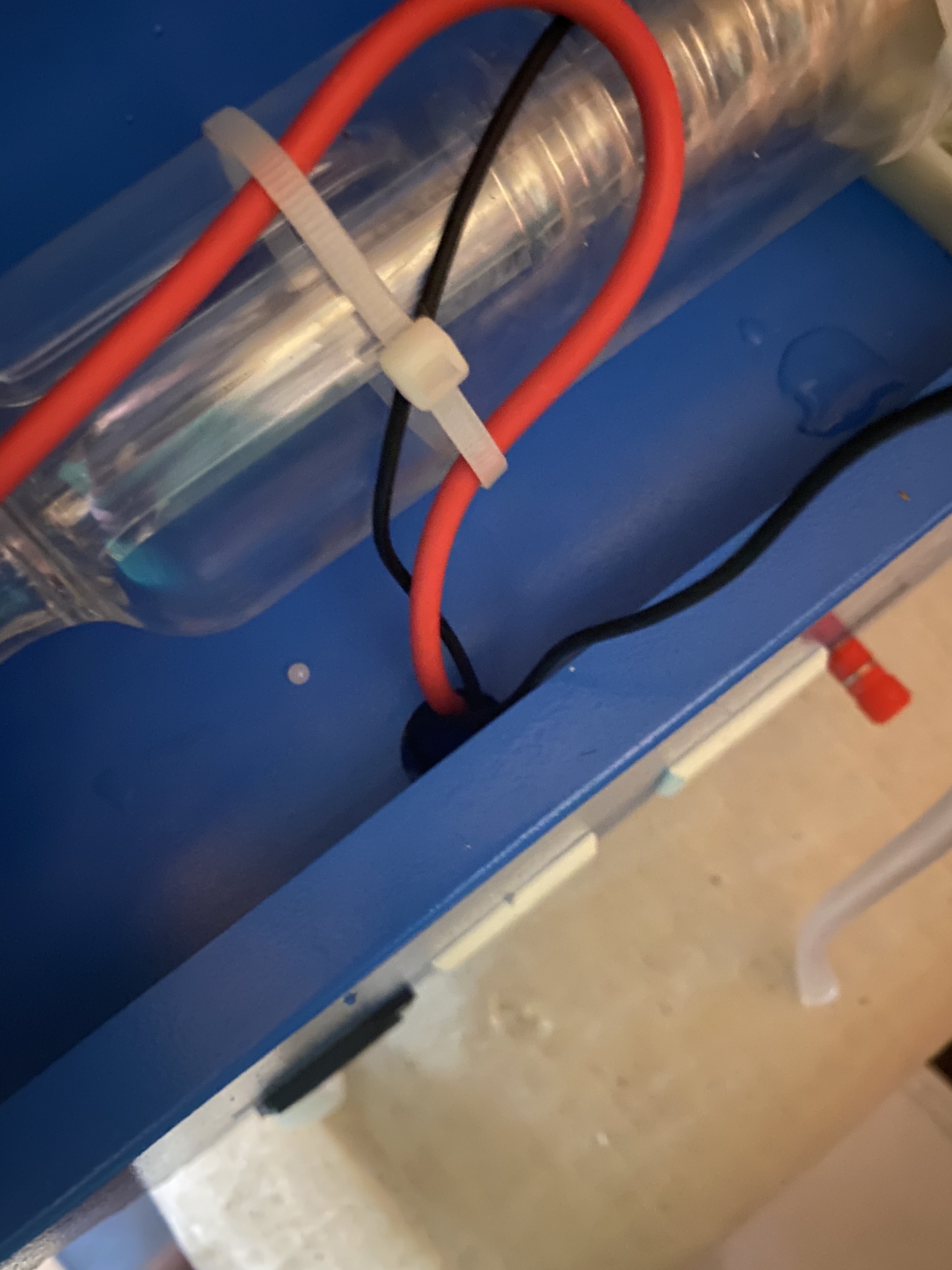
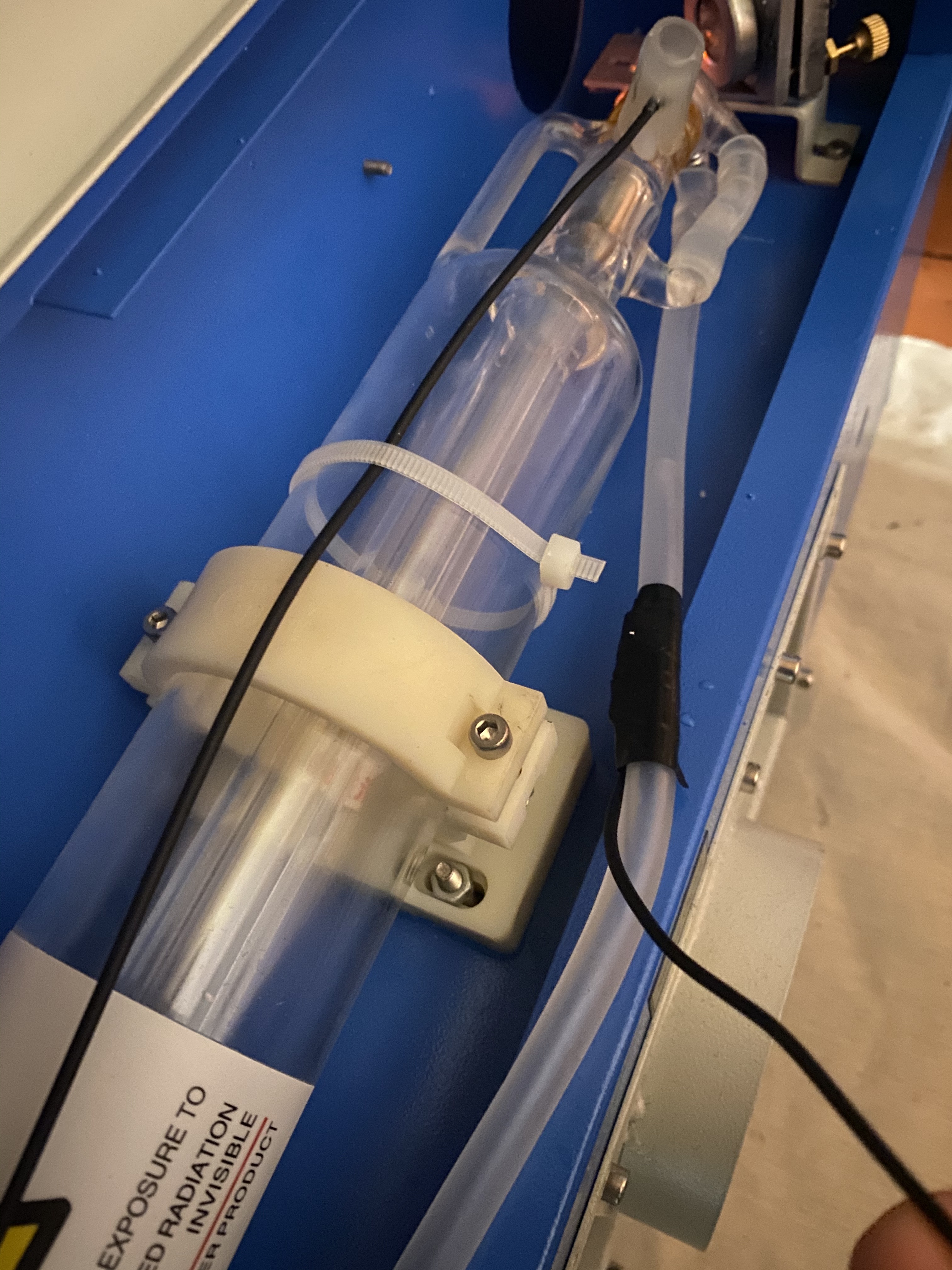
Thanks all so far for all the advice. So I looked at my laser tube again. There are 3 wires coming from the machine. 2 black and a red. Assuming the red is the +ve and is connected directly to the +ve of the tube. And one of the black is the -ve, also connected directly to the tube. The other black is taped with electrical tape to the outlet water tube. So, I’m assuming I am going to need 2 high voltage connections for the +ve and -ve wires to connect to the new tube but wondering is the 2nd black an earth?Pics below.
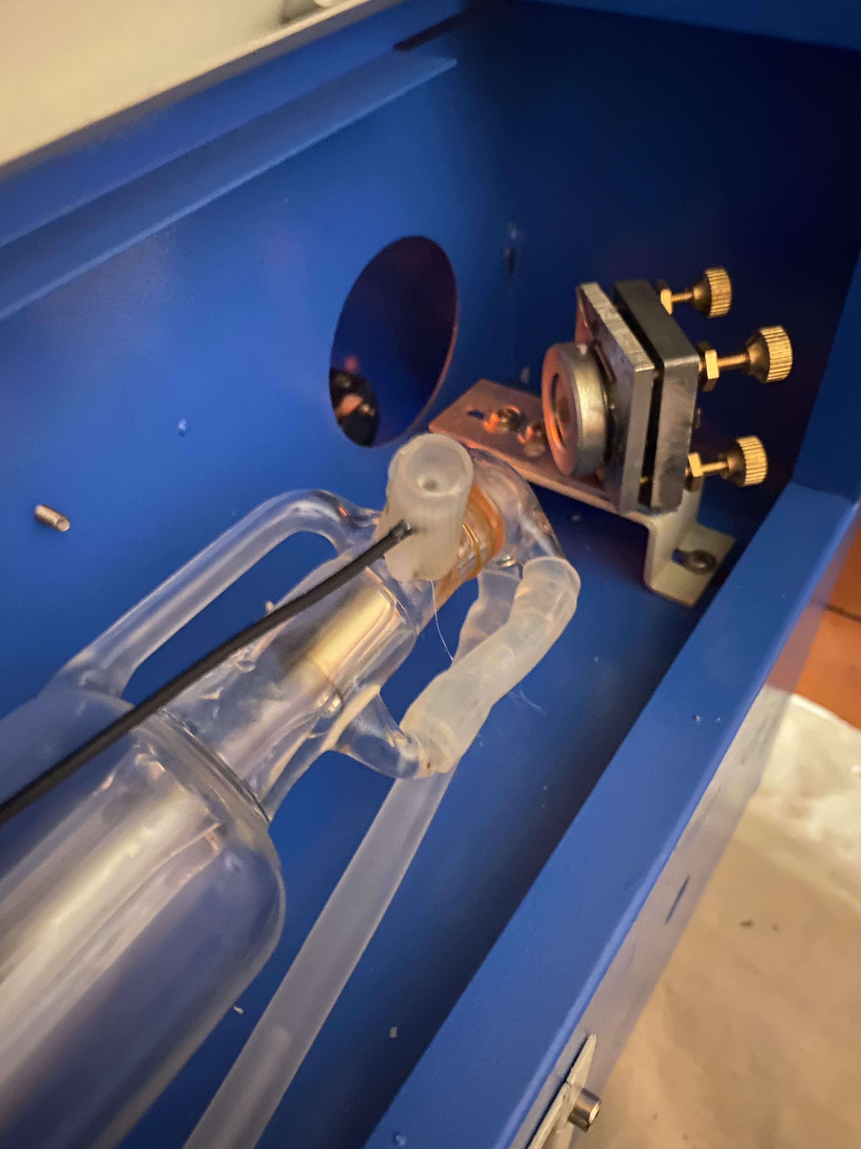
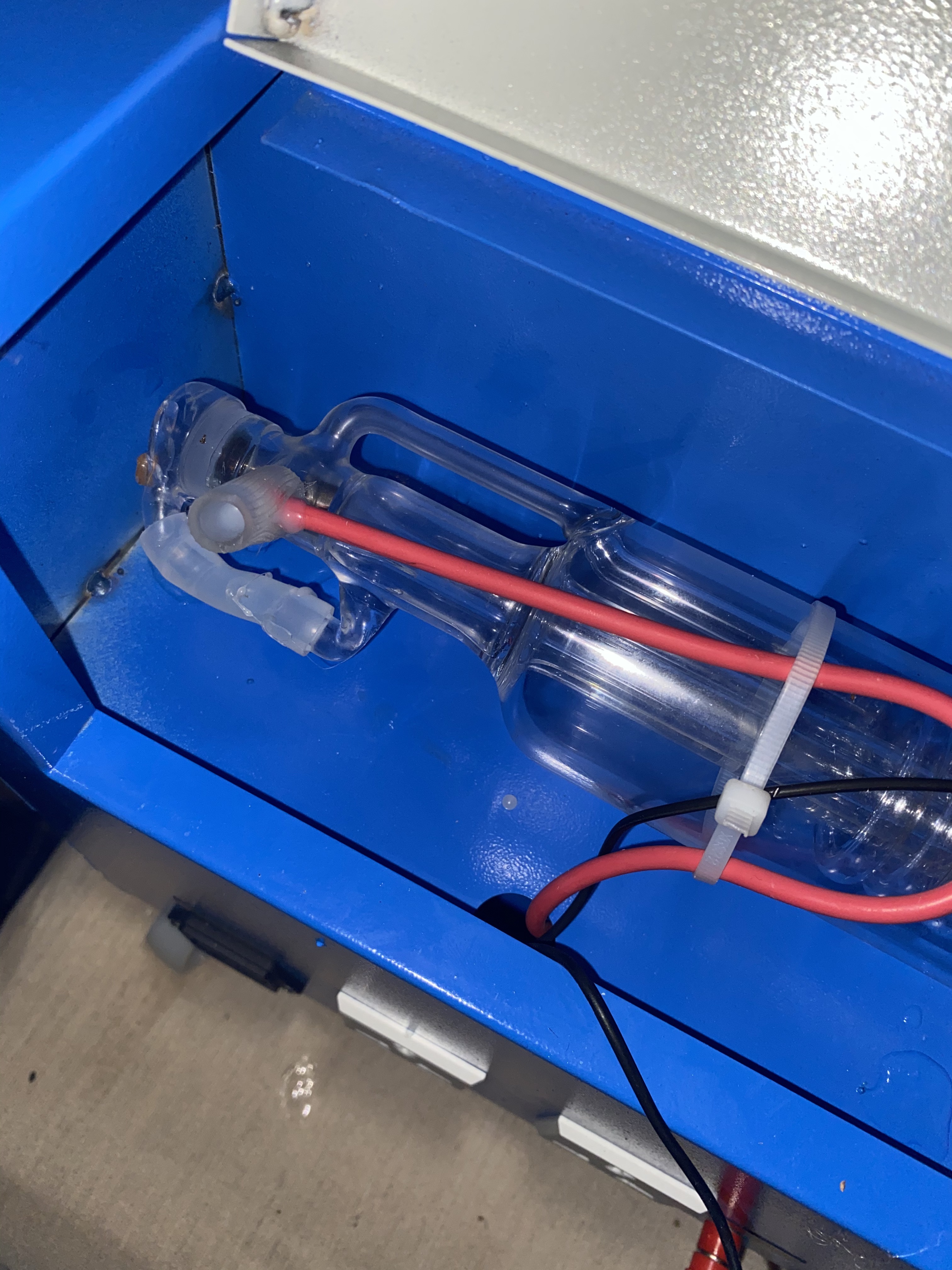
You only need one HV connector for the red wire.
The other black tube connection is the cathode and is connected to ground so it does not have to be HV.
The third connection looks like a temperature sensor. Have not see one like that before. Where does the other end connect?
In any case you should not have to mess with it as the water tube will not be replaced, just disconnect and then re-connect.
4 Likes
Many thanks @donkjr The black cathode is connected to the tube, so what you’re saying is just to connect the cathode on the new tube to the same on the machine in the normal way (twist together and seal with tape?)
Yes, as a default just re-attach it like it currently is. This is a low current connection that should be at ground (no voltage).
If it is just wound around the pin I prefer to have a slip on connection for this end since it is such low voltage and current. I took a pin from an old connector that slid on easily and soldered it to the wire and then slid the pin on the post.
Either way should work.
Do not put any force or heat on either of the posts or they may crack the tube.
The other end of the cathode wire should go to:
… your meter if you have one
or
… to the FG on your LPS if you have a digital panel.
3 Likes
The one with the tape its temp sensor, i had the same on my machine.
3 Likes
an electrician friend of mins just dropped by (the tube isn’t here yet) but thinks that these would be good enough to connect the wires, obviously tape over with electrical tape. The reasoning (I think) is that the 20,000+ volts aren’t generated at this junction seeing the tube is already wired. It’s just joining the lead coming form the power supply to the lead that goes to the +ve terminal on the tube. Thoughts?
Do not put a connector on the Anode side. The anode side does not need any connector it is just wrapped around the post. Connectors on this end can create sharp points that emit corona and create other arching problems.
Just wrap the wire tightly around the terminal and reinstall the tube and silicon as the video above shows. If you don’t have a connector for the cathode just wrap it as well.
How was the cathode side connected on your old tube?
Don’t use electrical tape anywhere. The connections get covered with a silicon tube and filled with silicon as is indicated in the video and as your pictures above show.
1 Like
the tube seems as though it comes with the wires already connected to the anode and cathode with a leading wire coming form each to enable connection to the machine. This is what I bought.
The reasoning (I think) is that the 20,000+ volts aren’t generated at this junction seeing the tube is already wired. It’s just joining the lead coming form the power supply to the lead that goes to the +ve terminal on the tube. Thoughts?
Your electrician friend is ignoring the potential from the junction to the grounded case.
The dielectric of electrical tape is about 600V. That’s not 20,000V. Your friend probably doesn’t have HV experience. It’s just not the same.
3 Likes
yeah, but the rest of the wire length is just covered by a thin red tubing though?
Since your tube is coming with pigtails installed:
For the negative, you can use any type of splice you get from the home store. I would solder or crimp on the splice and finish with heat shrink. This wire must stay away from the HV (red) lead. It should be routed directly back to the LPS pin -L, usually the leftmost pin and connection on the LPS.
CAUTION: do not connect to L which is on the rightmost pin and connector.
Before we talk about the anode connection it’s important to realize that 20,000-volt connections do not act like the kinds of connections we normally use. What we normally know as “insulating materials” do not adequately insulate at this voltage. Other fabrication and environmental conditions can also cause HV leak problems such as moisture, dirt, dust, and sharp points in the assembly.
HV easily arcs through conventional connection and insulation methods
- 20,000 volts can easily arc 2" to a grounded surface
- 20,000 volts creates corona and corona tracks from sharp points
- 20,000 can create conductive tracks in dirty, dusty materials, etc when not properly insulated
- 20,000 volts at 30ma is capable of killing you …
For connecting the anode wire your options are:
- Add a HV connector [like the one @NedMan suggested above] inline with the existing HV cable and the new tubes pigtail. This makes it easy to change the tube in the future. HV connector must be installed correctly. I seal the ends with high dielectric constant silicon RTV **.
- Solder the HV pigtail end directly into the LPS (like is it currently connected) which requires you to get access to the inside of the LPS and unsolder the current wire and solder in the new pigtail. This only works if the pigtail is long enough to reach your LPS. This connection is the best as there are no discontinuities in the HV wiring. However, it is the most involved method and it requires access to the HVPS internals.
- Make your own splice using plastic/silicon tubing and HV resistant silicon.
- Slide tube over the open end of the pigtail. The bigger the diameter tube the better. Silicon tubing generally can have a smaller diameter than home store plastic tubing.*** The key is to get enough thickness of silicon to adequately insulate the HV from its surrounding. The tube should be sized such that it will extend at least 1" from either side of the joints edge of insulation.
- Join the pigtail to the existing LPS HV lead by twisting them like this:
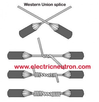
- You can leave the joint like this but I like to solder it. If you solder it use bulb soldering****. Soldering or not, ensure there are no sharp points of wire sticking up.
- Apply a liberal amount of the RTV over and around the joint.
- Slide the tube over the joint and RTV. You want the RTV to fill the tubing with no air pockets.
- If the tubing is not full of RTV add more into each end of the tubing. Pretty is not important here, thickness is!
- Let the splice cure for 24 hrs before applying power
Stuff to make your own splice:
** Blue RTV. You may be able to get this at auto supply stores, Walmart or https://amzn.to/3qc9xob
*** You can find silicon tubing on Amazon I recommend 1/2 or larger. I have also used larger diameter 1/2-3/4 PVC tubing as an alternate material. Its the total thickness of silicon that does the insulation work.
****https://www.spellmanhv.com/en/Technical-Resources/FAQs/Technology-Terminology/What-is-Ball-Soldering
3 Likes
@Marko,
This is 20,000 volts. Unless you are experienced with HV power, you may not realize this does not act as any electric circuit you have ever been exposed to.
The red wire is a special HV wire that is capable of insulating this high of voltage. NO other common wire is and this voltage has no problem penetrating electrical tape as well as many other common materials.
If you do not use HV connection and fabrication techniques and materials your machine may be unsafe and also may prematurely damage your LPS.
4 Likes
Thanks everyone for the EXPERT advice. I tend to think the HV connector is the way to go, if I can get one. I have emailed a local electric wholesaler to ask if they have them here. I’m in Ireland but I sent the US link above to give them an idea of what I need and explained why. I’ll keep you informed. the tube is due to arrive tomorrow. If it does I’ll update as well.
1 Like