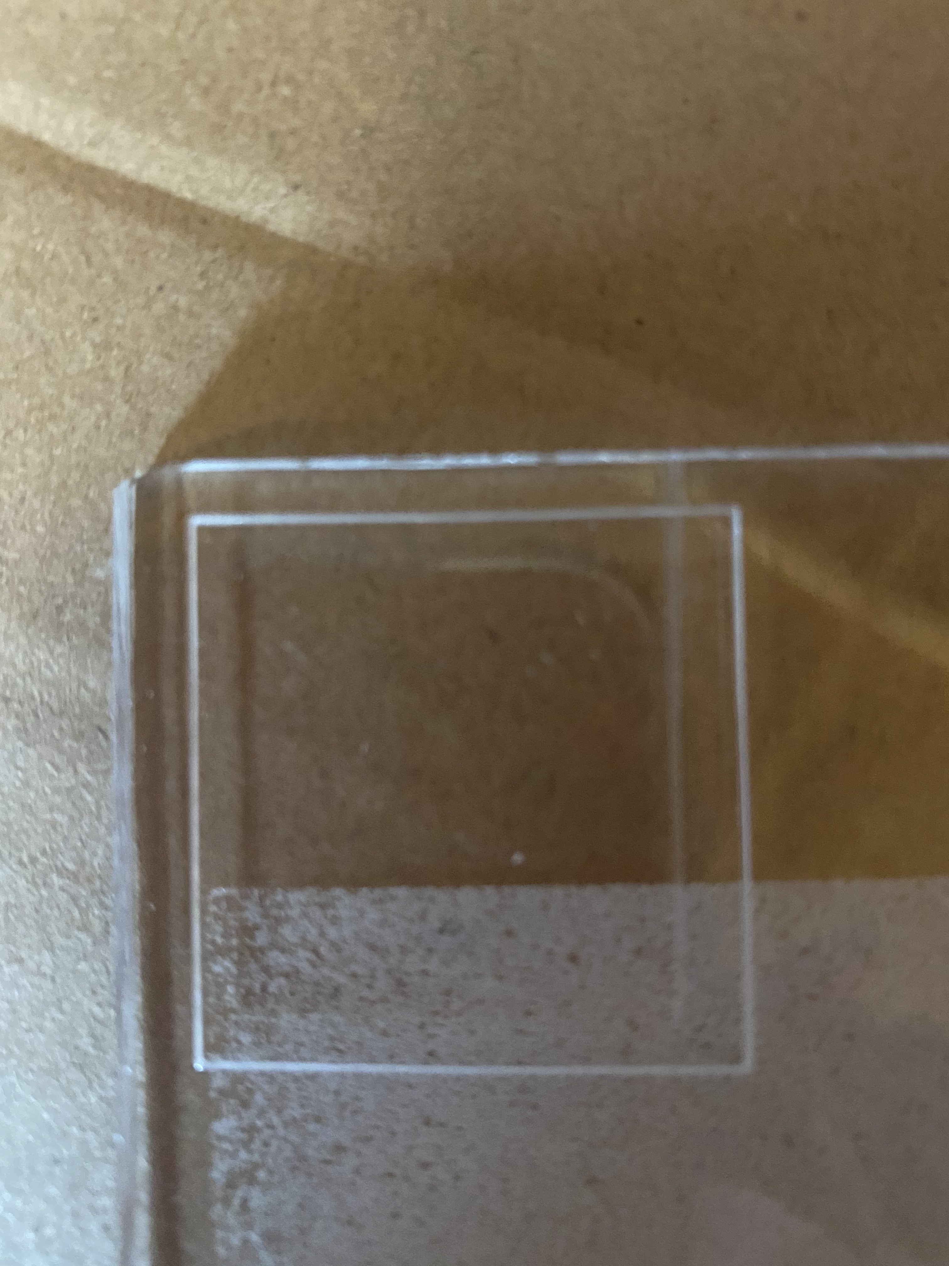
Hi anyone got any more ideas? The mirrors seem aligned, this doesn’t happen for raster or vector engraves. Doesn’t happen along the horizontal, only the verticals. I checked the mirrors again, I tried reduced powers and obviously at very low power the 2nd lines don’t appear but it take multiple multiple cuts to cut the perspex. There is obviously something wrong but I just can’t figure it out.
Have you tried just cutting a square?
Does that do the same thing?
1 Like
I will try a square in the morning thanks. Is there a reasoning behind why this might work? I also reduced the thickness of the line but it had no effect at all. It’s getting frustrating… 
Just stabbing in the dark since nothing else worked.
I sometimes find that simplifying the job will lead to hints.
3 Likes
I looked at th previous thread, and in there I asked a question to which I didn’t see a clear answer:
Also:
I still think there’s a chance that you are getting a reflection from the beam hitting the inside of the nozzle, or something like that. Please upload here the result of four test fires:
- picture of witness tape before first mirror
- picture of witness tape before second mirror
- picture of witness tape before head mirror
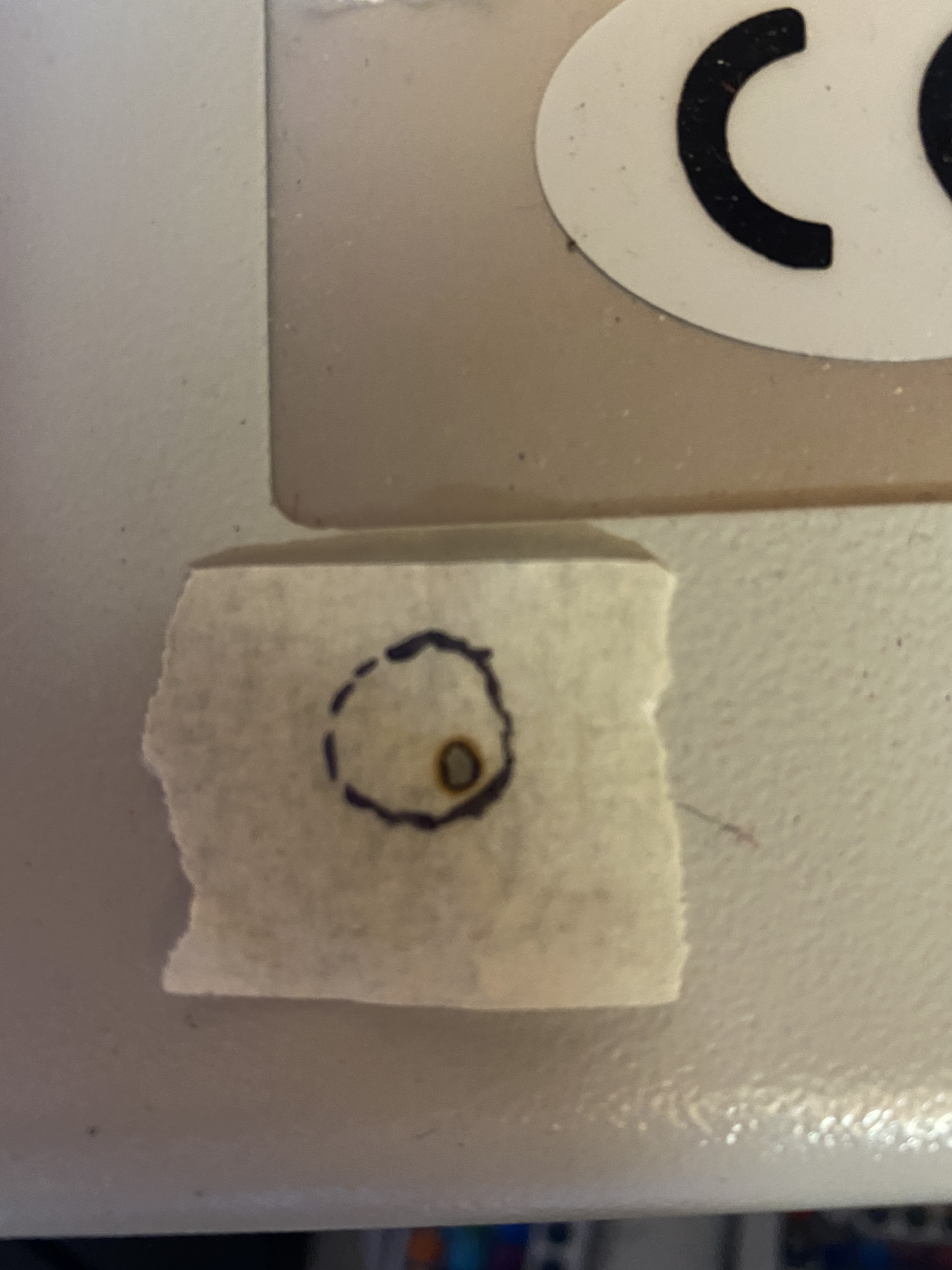
- picture of witness tape on the bottom of the tube, with the nozzle removed, and with the outline of the tube marked clearly
3 Likes
I agree this looks like a reflection from somewhere.
Thanks guys - I hope to get the masking tape tests done this evening and see where we go from there 
1 Like
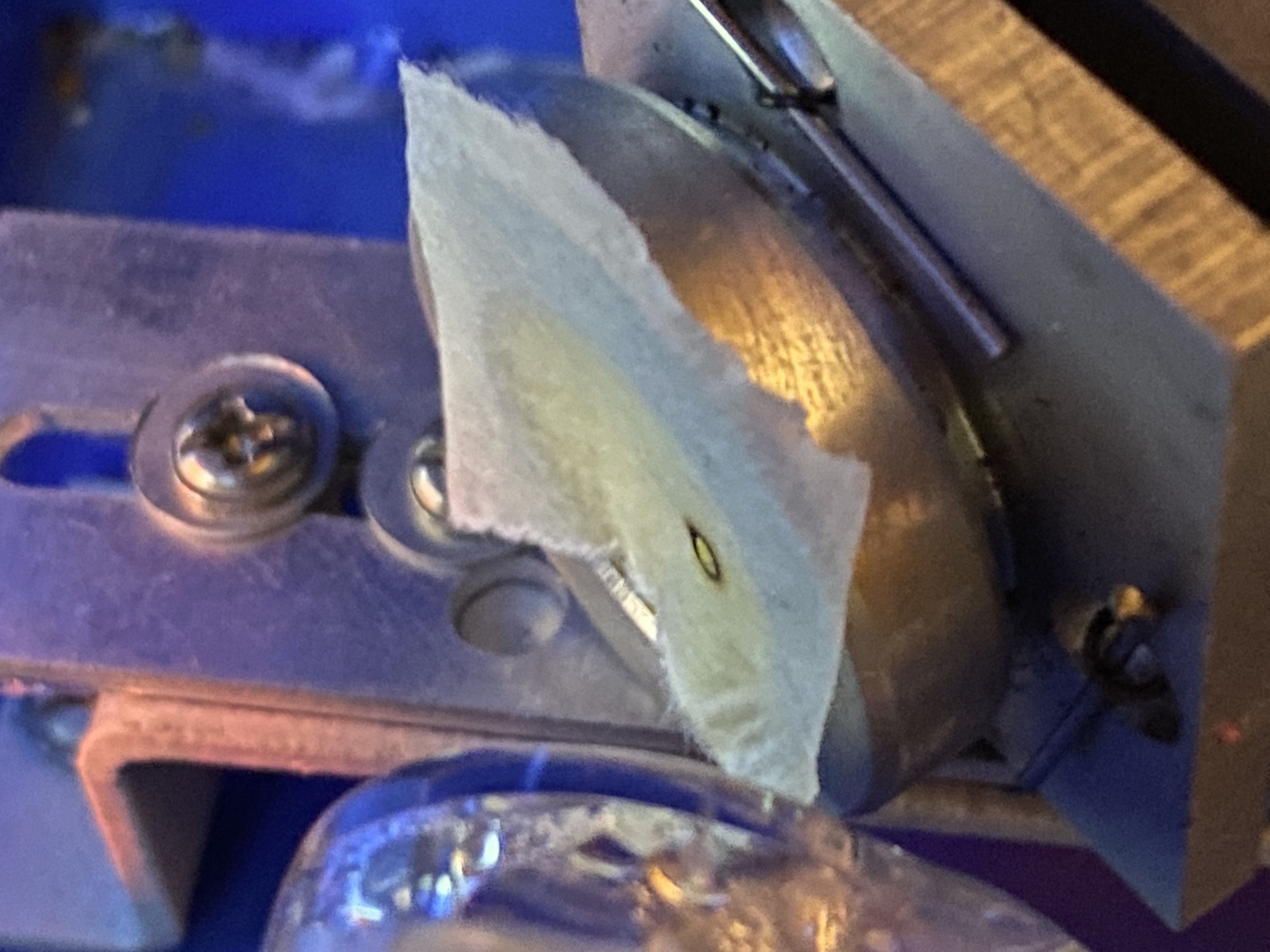
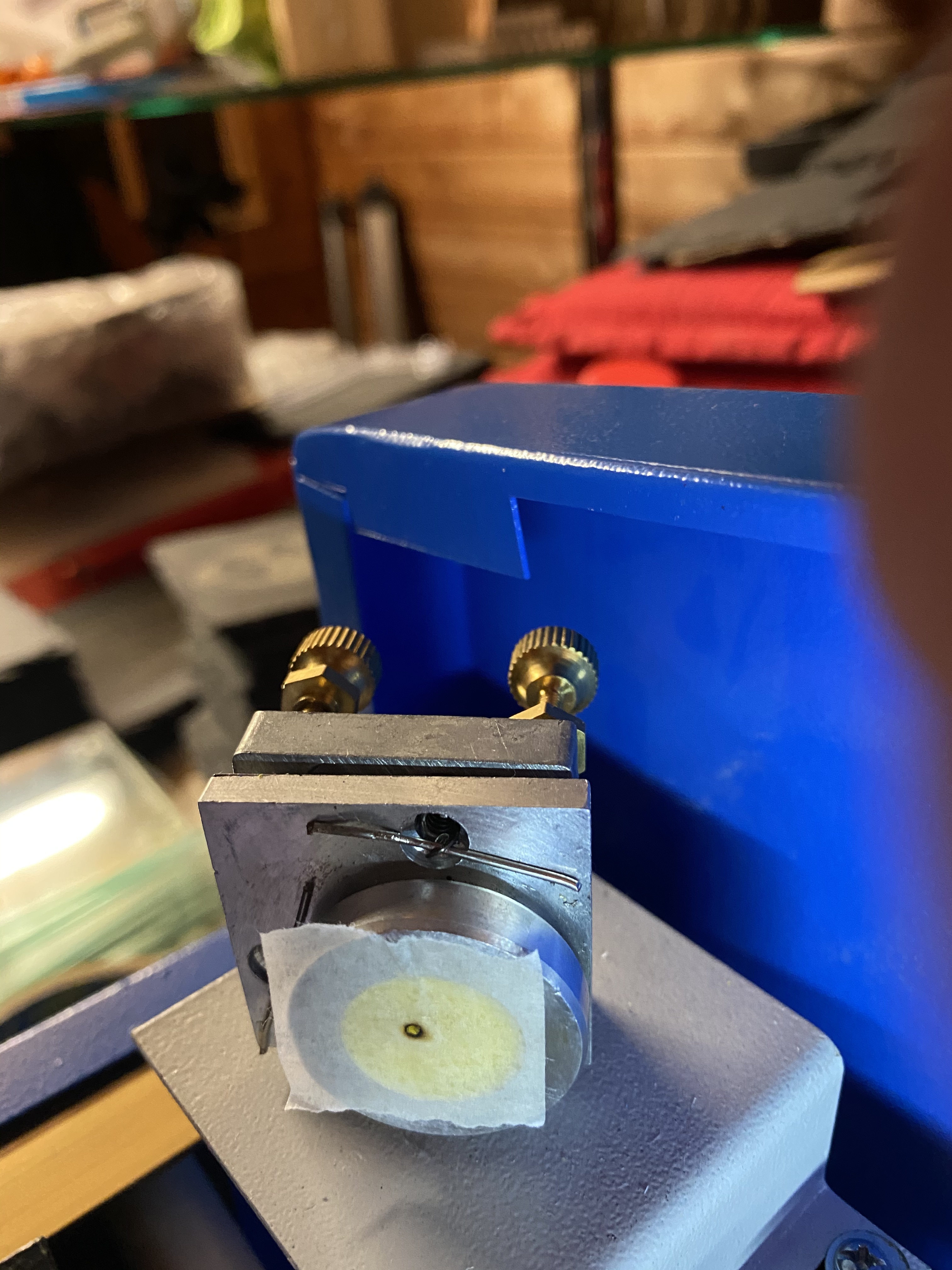
ok guys, seems to be a problem at the end a you had indicated. The pictures are in order. Mirror 1 seems centrerd, as does 2 and 3 but with the tape at the bottom of the head with the lens removed, it seems to be at close to the furthermost edge at the bottom right (forgive my hand drawn guide for the nozzle!!)
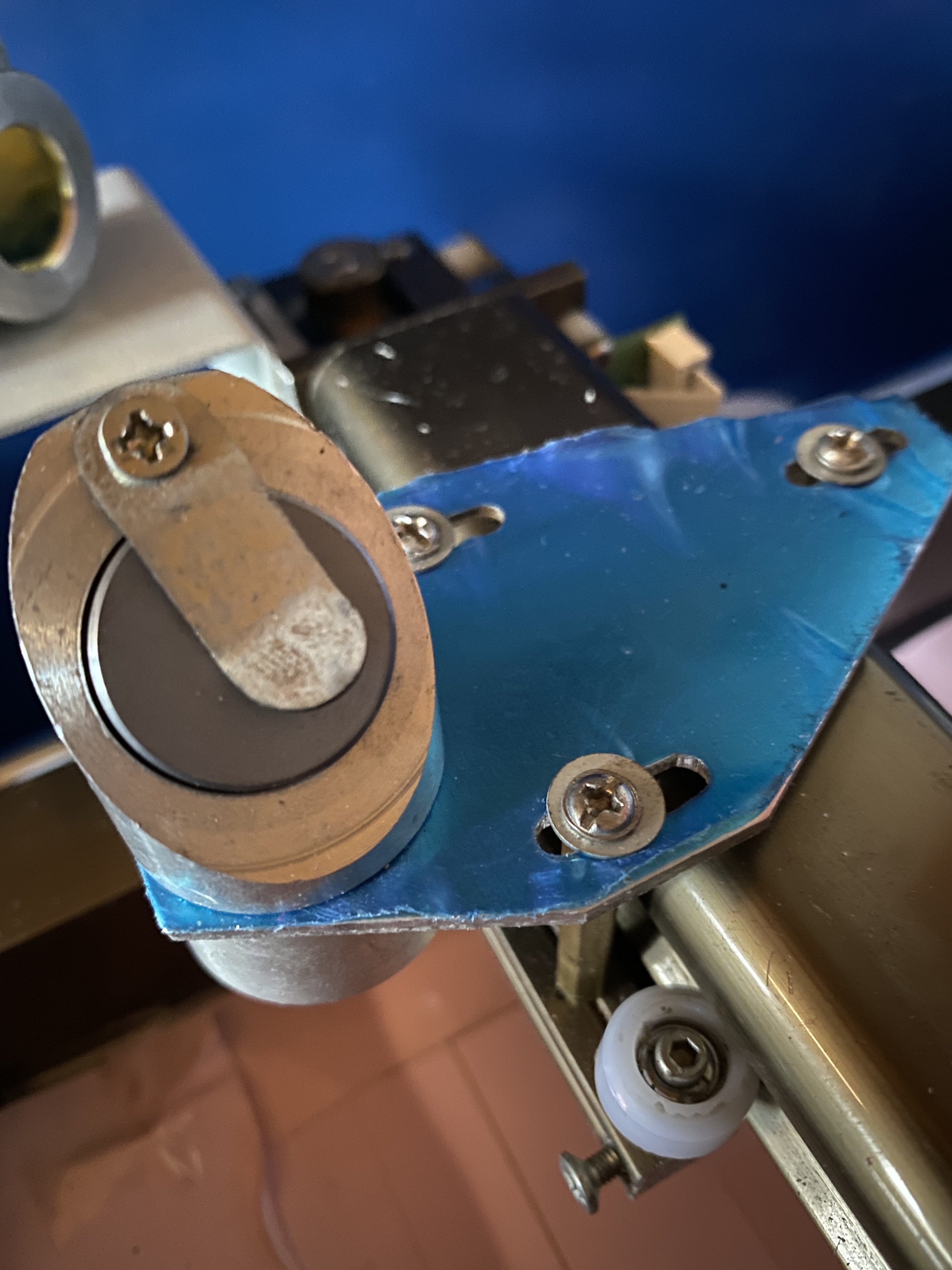
Mirror 1
Mirror 2
!
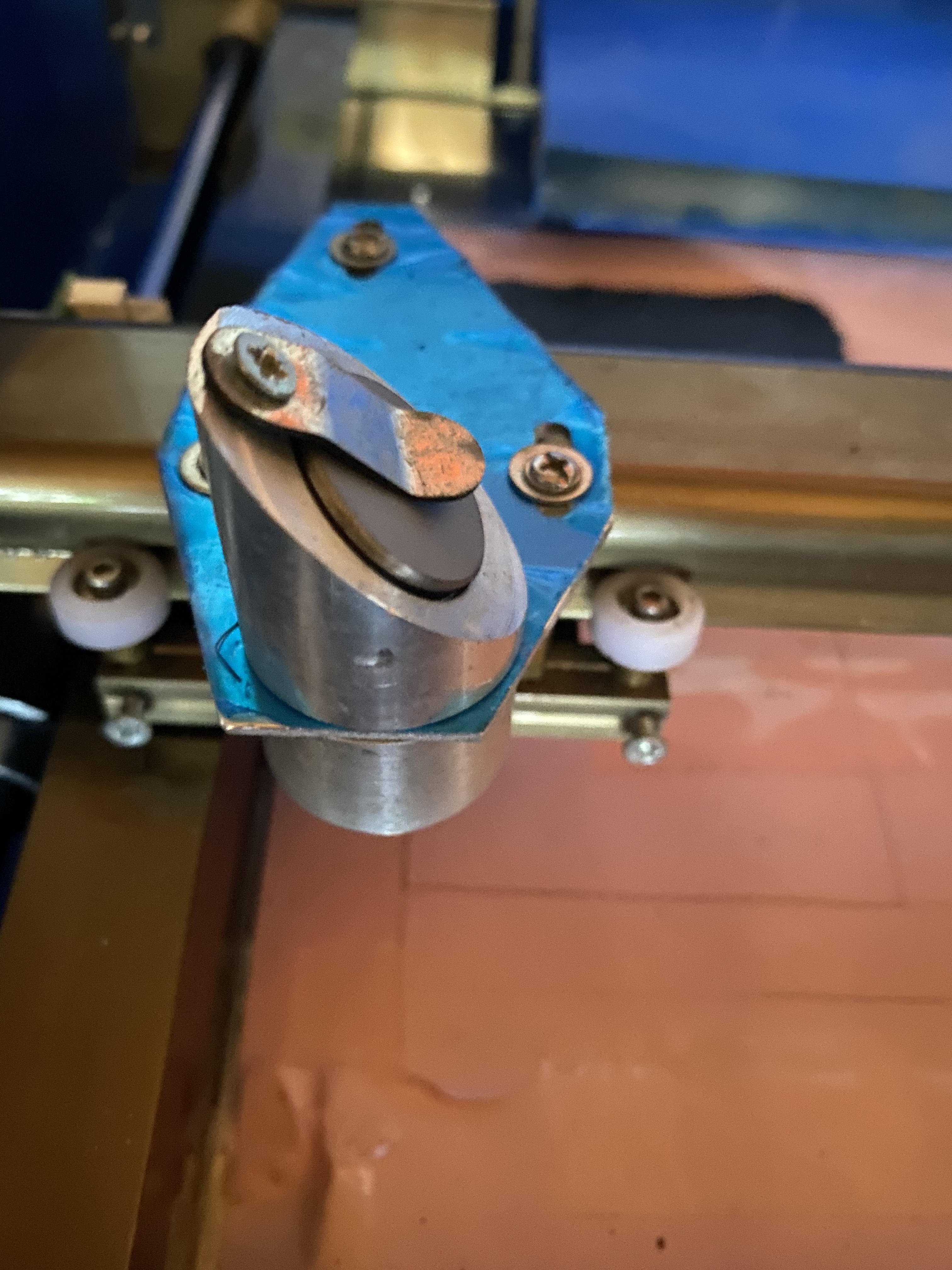
Mirror 3
!
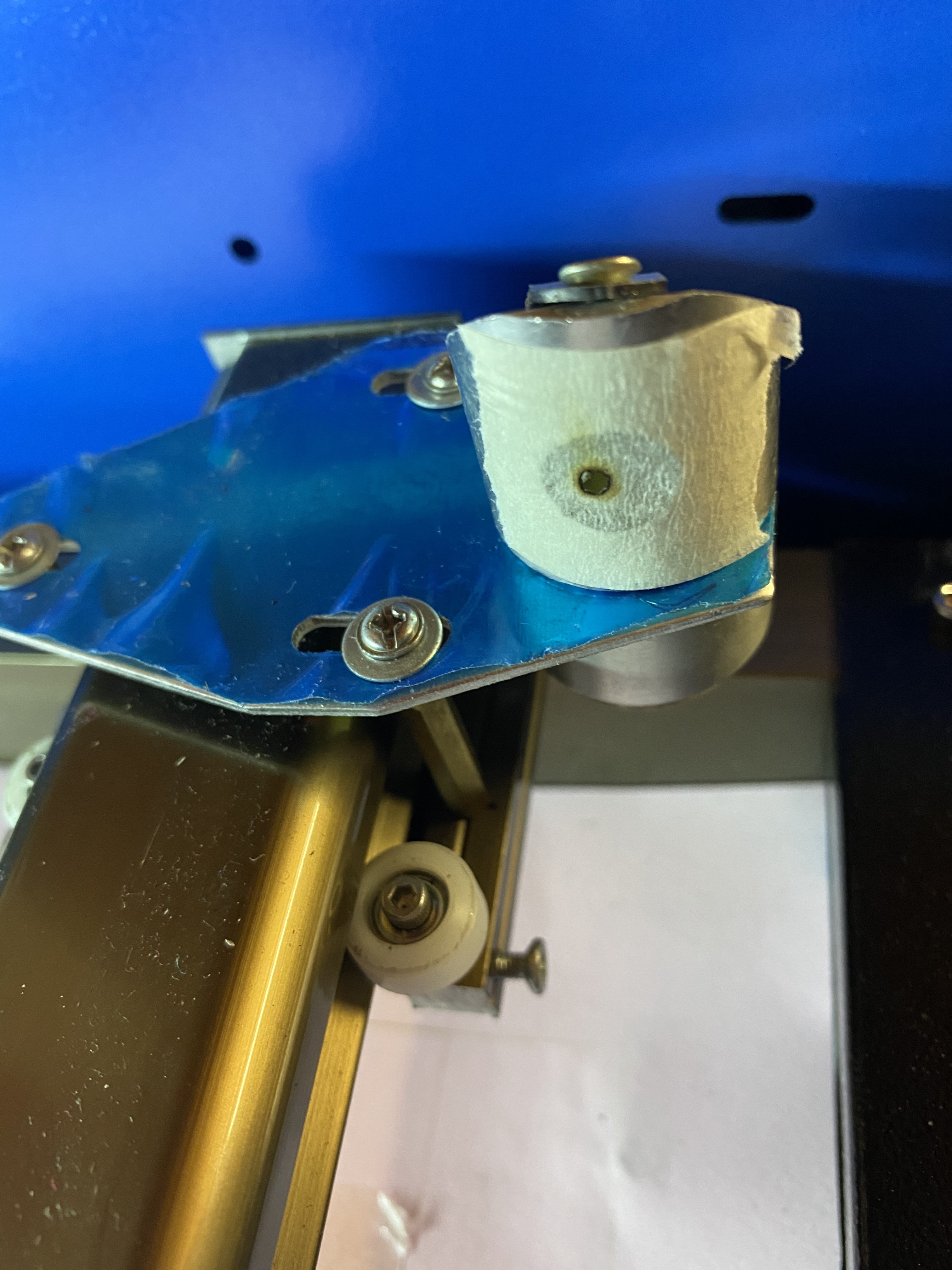
Bottom of head with lens removed taken from below the nozzle in ‘selfie’/reverse mode. It seems to be at the edge of the nozzle but not touching
Actual tape when taken off and nozzle outlet hand drawn
!
1 Like
Hey Mark
Mirror 1 looks out to me? Doesn’t look centered?
so I need to adjust the tube then? But if the other tests 2 are fine then is it not an issue with mirror 3? It def doesn’t seem to fit as snugly in the head than the previous.
Your mirror 3 is not adjustable, so you have to find where you need to hit mirror3 to go through the center of the nozzle. It may not be in the middle of the opening!
American Photonics has an alignment tool that may help you:
In particular, they have a video showing that in a particular K40 head they have (not the same one you have), aligning the beam with the center of the opening in the K40 head doesn’t cause the beam to align with the center of the nozzle.

You don’t have to buy the tool to understand the problem, but the tool isn’t expensive relative to the cost of making it and in this case it might make things a lot easier to get into alignment. I can recommend watching all four videos on the product page.
Fixing this will not only remove the ghosting but also give you a cleaner cut because the beam will be better focused. I don’t know the orientation of the offset; to the extent that it is front to back you can adjust mirror 2, but to the extent it is left to right you need to shift the beam path up and down (because 45° mirror).
1 Like
the offset coming out of the nozzle is below and right of centre
“Below” depends on perspective so I don’t know whether you need to move the beam toward the front or the back. That will be adjusting the location of mirror 2, one way or the other.
Towards the right of the unit means that the beam enters the head too low. Moving it up makes it hit the mirror further to the left, which makes it exit the nozzle further to the left. So you need to shift the beam path up by the distance it is right of center.
1 Like
Thanks. The beam is to the front right relative to the machine. So I’ll go play now with mirror 2
Yup, you’ll need mirror 2 shifted back by the distance your tube witness is off center.
For shifting the beam up, my laser is in cradles with screws for height adjustment. I think K40s don’t come with cradles with screws, so you probably have to shim it. I’ll leave it to those who actually have a K40 to help with that part! 
2 Likes
Are we ignoring this:
1 Like
I don’t think we are. I wouldn’t expect sliding around on the registration face slightly (due to slightly smaller diameter?) to have this impact on alignment. I could be wrong but I was at least not ignoring it. (If it’s loose it might well also need to be tightened somehow, like if the clip got stretched.)
Does this head have any possibility for false registration for the mirror, such that the mirror could be mounted at a tilt?
The beam needs to be in the center of the first mirror.
My guess is that the beam is not running parallel to the gantries X & Y axis as it traverses from mirror to mirror.
When the beam is far off from the gantries axis it’s a hard thing to see just looking at the placement of the beam on the mirrors. It’s a 3D problem.
What happens is the angle of the beam entering the mirror is wrong and then you adjust the next mirror to compensate for it. By the time you get to the non-adjustable mirror 3 it’s entering that mirror at an angle and the reciprocal of that angle causes the beam to hit the lens off-center which causes it to exit the lens at an angle. If it’s bad enough it hits the side of the nozzle.
There is not much room in the nozzle so it often reflects energy off the side. Consider that the beam is not a perfectly round cylinder of energy. It is gaussian so it has some power in the tails of that distribution that can be reflected from any surface that does not absorb all the energy. Even if the center of the beam does not hit the side wall the tails of energy might cause a reflection.
The beam has to enter mirror 3 parallel to the X-axis and at a right angle to the Y-axis hitting that mirror slightly off-center so that it will fold at exactly 90 degrees or perpendicular to the bed.
You can test to see if the beam is exiting perpendicular to the bed using this method.
- Tape a target to the bed.
- Set the bed a focal length
- Fire at the target
- Move the bed down 1/4"
- Fire again
If the marks on the target move relative to each other the beam are exiting the head at an angle.
Note: if the bed is not kept perpendicular to the gantry as you move it down this could also be a source of error but that is not usually a problem.
Profiling the entire path.
I dealt with this overall problem on my machine some time ago by making sliding targets aligned to the gantry so that I could accurately profile the beam as it traversed the X & Y.
There may be a simpler way to try this:
You can try this and it occurs to me as I am thinking about this problem that this same method could just use a piece of stiff graph paper held in a consistent reference to the gantry. This template is not as accurate as the acrylic tools but probably good enough to see a big problem.
This target would be placed and held vertically at various positions along the beam path and test-fires would be performed over the top of each other at positions between the mirrors. The result is that you could see how the beam moves along the path in X and Y relative to the gantry.
This attachment can be printed 1-1 on stiff card stock (or glued to something stiff) cut out and then used as described above.
This template mimics the dimensions of my tool. The circle is the region that the beam should be in. It can only be used for the path from mirror 1 to mirror two. If the laser is not parallel to the gantry axis it will likely show it along that path. I will create a second template for the x later today.
EDIT added the X template. I did not dimension this one but you can print it 1-1.
Note: I have not tested these templates.
K40 3D alignment target.pdf (793.3 KB)
XAxis3DAlignmentTarget.pdf (719.0 KB)
3 Likes
Thanks for this again. I think I may start again and look to get the laser exactly in the middle of the first mirror by somehow adjusting the actual tube? And then take things form there?