Apologies for not responding earlier>
I got tied up with work stuff…
But I will attempt to go through the threads now - I’m clumbsy with this so bare with me…
No need to apologize! Respond as time allows. ![]()
Hi Michael and other friends of my simple (Pathetic?) project.
I did watch the video of clough42 and did also find it interesting and informative, so thank you for that - Good information/education. I just watched a bit of it now, before posting this.
I like the way this system works, and it seems applicable to my application, as it would (apparently) cater for slight undulations of a thin aluminium (Aluminum, to you guys… ![]() ) plate on a platform for engraving. If you get my picture…
) plate on a platform for engraving. If you get my picture…
I don’t quite understand the “Tap Follower” detail, Michael - I must be missing something here, but am keen to know.
(Maybe not here if it interferes with the thread topic, but…)
Love that joke - Made me laugh.
FreeCad I am going to look up now… Thanks for the heads up.
More rubbish from me shortly, as I go through the post responses, with thanks to all involved.
Very much appreciated!!!
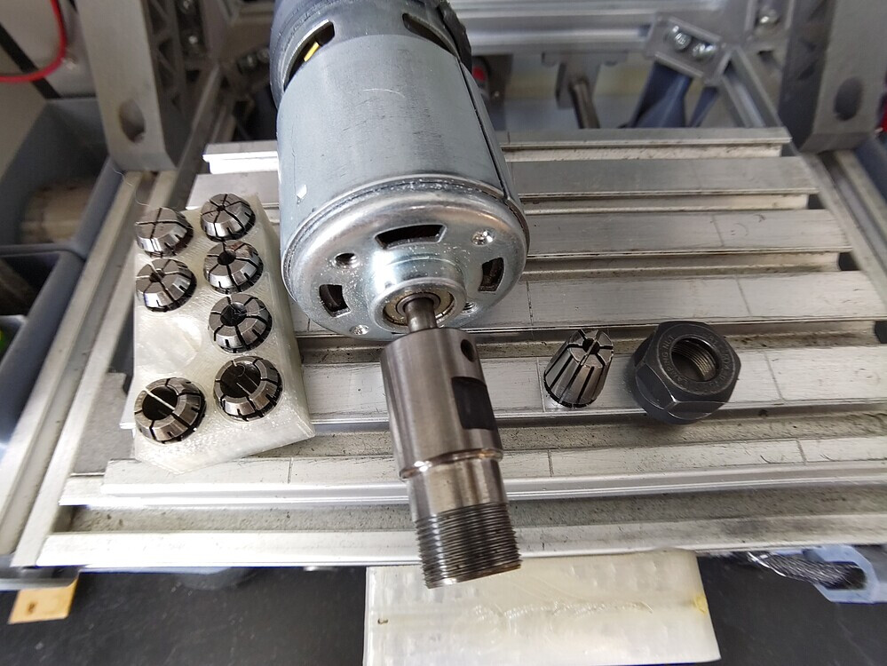
Before I have read the remaining posts, this is exactly what I was picturing for my application.
Can it spin to the 10,000 RPM that the engraver runs at?
I’ll read the later posts now, and hopefully haven’t insulted anyone with my approach to replying to posts…
Jonathan.
I watched the videos on this topic, and thank you Michael for this information.
If I can find a spring loaded ER11 collet system to hold such a spring loaded Diamond Drag tool, I would buy it - It seems to satisfy all the functional requirements I have.
Yes I am price sensitive, but I believe in proper systems to gain a proper result.
Just to make sure this is clear, the diamond drag engraver doesn’t spin. You leave the spindle turned off if you chuck a diamond drag engraver init.
Here’s a post I made about machining a set of tap followers that includes translucent animations:
If the tip of a pointed-end tap follower (for larger taps) were a diamond, it would be a diamond drag engraver.
If you want to get started with FreeCAD, download this free book to get started. FreeCAD has a fairly steep learning curve — don’t be surprised.
Here’s a tutorial on how to bring images in and get them to scale:

Here’s a video on getting text where you want it:

This might help you enter text on a spreadsheet inside FreeCAD (yes it has built-in spreadsheets for parametric modeling!) so you just tweak that text for the next label:

In general, his tutorials are good:
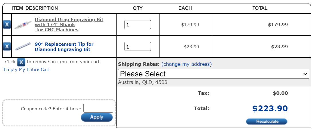
The only one I’ve found so far with an end that will fit an ER11 collet is $180 and is in the US so add some shipping to that:
That would be an alternative to designing and printing a bracket, naturally.
I feel a little embarred now… I guess the “Drag” part would have been self explanatory, ![]()
Thanks for the clarification.
Michael, you are a bloody legend for this information.
$180 USD is ok as I seem to have less options. Hurts none the less…
This appears to be a viable option, so I’m in.
I assume I can either machine down the shank in a lathe (From 1/4" to 1/8" or machine up an adaptor to fit the stupid 3mm (1/8") collet I have. (?)
Shipping I will have to cover, but if it works, I’m fine with that.
… just read the link details and it sounds good for me.
Thank you very much for your advice and direction.
You guys are kind with your information and support, and that is refreshing.
Thank you.
JK
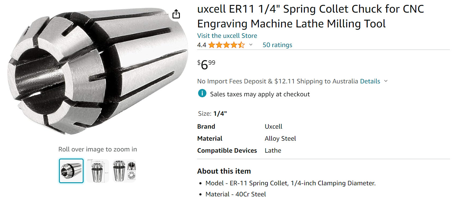
Just buy a 1/4" ER11 collet. You could get a complete set of all the metric sizes, plus an additional 1/8" collet, plus a 1/4" collet. Or an imperial set. Or a set of just 1/4" and 1/8". Or just a single 1/4". Totally depends on what else you might want to do.
https://www.amazon.com/Precision-Spring-Engraving-Milling-1-0mm-7-0mm/dp/B0B77B748B
https://www.amazon.com/Paddsun-Spring-Engraving-Machine-Milling/dp/B07JWG4HWR
https://www.amazon.com/Collet-Engraving-Machine-Milling-ER11/dp/B0C3ZXX1ZF
https://www.amazon.com/Collet-Engraving-Machine-Milling-ER11/dp/B0C3ZYB8BZ
You don’t have to buy them from Amazon. And no particular reason to buy any of those particular sets, I just chose them completely at random from a quick search.
Brilliant - Thank you sir.
I’ll check these out.
Much appreciated.
Thanks for the guidance and advice, Michael an all involved.
Purchased…
Purchased…
So thank you sooo much.
I will now check out the software available, as was mentioned above… sorry - forgot who that was and can’t seem to navigate up at the moment to check…
CAD = Michael again.
Also, thank Owen for your help - Very much appreciated.
I might look around in this forum for other peoples interesting projects… a little more interesting than mine I would suspect, but nice to get motivated by others!
Cheers for now.
Jonathan.
1 Like
PS - I might have given up on this project (or gone a more expensive route) if you guys hadn’t given me the support you have - Bloody Legends, in my book!
Just for a boring update, to a well supported small project, and for Michael (And others who contributed) to understand that I have not been stagnant in my endeavours to get the final (?) processes under control.
I’m checking out software (Suggested platform mentioned above) to get a base template (ID plate) virtually imported into a FreeCAD project and layer windows of areas for data input, to populate the base surface (ID plate) for etching to be occasioned in the window areas.
That is, to be able to etch the plate when it is secured on the domestic milling system I have. If that makes sense.
That is my current challenge.
I have also designed and fitted a plate holder that is within 0.1mm of the ID plate fitment. Works very well for location and security of location.
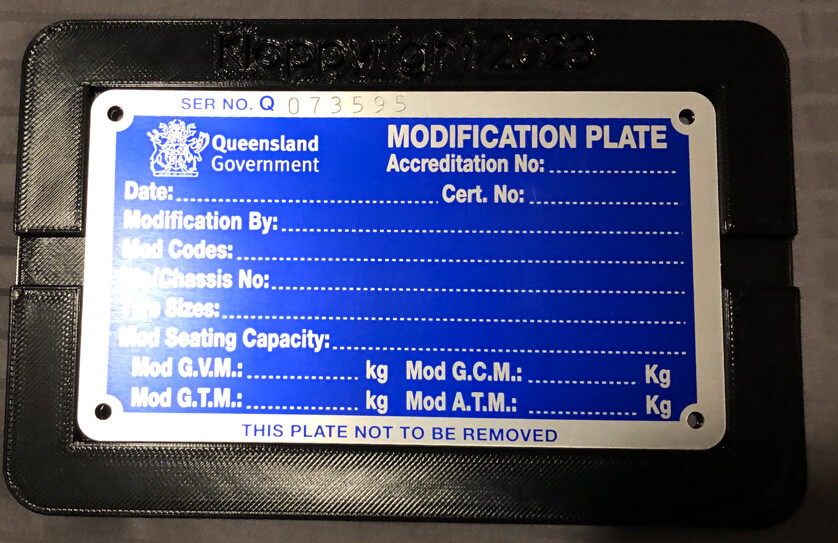
No movement of the plate.
But understanding the method of locating standardised “windows” for data input to all of the areas needing data (see dotted lines on the image) is proving interesting and a learning experience.
I think I am getting there via the learning experience to understand the FreeCAD software, which is OK, but slow.
Obviously an educated person might be able to put me on a direct path to achieve the goal, but that would negate the leaning of how the software actually operates.
I am open to both direct direction and learning my own path.
Thanks for tolerating my venture into a world I have not known before - It is exciting, tedious and frustrating while revealing satisfying stages at the same time. Much so a pleasure of experiences.
Thanks for sticking with me… Very much appreciated.
Jonathan.
1 Like
Apologies for the long post…
Hi Michael & other bored watchers. Apologies for the delay in comms, but I’m sure you have other more interesting things to do…
I am struggling with the damn “Candle” software to make my crappy Vevor C3018 CNC domestic mill to work.
I cannot seem to get a program sent to the unit and make it work.
I have looked at the FreeCAD software and played with it, but it doesn’t seem to save into DXL files or other formats.
I feel I might be missing something here…
Is this just me or is this really the case?
I ask that because I need to save some CNC milling files in a format to import them to my crappy mill, and it wants to see a specific file format, which is G-code.
I have a transfer program that converts CAD DXF files to G-code (Vector based to cartesian - should be straight forwards) but this damn CANDLE program (Which my C3018 thing runs on) has little or no reliability.
I do “dummy” runs with / without the cutter engaged in the material, to check the run path, but the damn thing stalls and sits spinning without moving part way of the process.
Tried many nights to progress, but to no avail.
Any suggestions on this or perhaps another program to spin up the CNC mill and control it better?
Candle seems to fail me every time I engage it. And I have to re-install it every time it fails.
I have made files in Solidworks and saved them as DXF files, convert them to G-code files, and they seem to be imported to CANDLE fine (Cutter paths all mapped out, etc.), but they simply fail when the operation is operated. Machine stalls with errors.
Frustratedly yours,
Jonathan.
Any suggestions are welcomed… or should I stick to welding steel bits together?
Try UGS instead.
It can save in many formats. I’m not sure what DXL is unless it’s a typo for DXF in which case yes FreeCAD can save DXF.
That’s what the FreeCAD Path Workbench is for.
Shouldn’t need that with the FreeCAD Path Workbench.
But also there are other tools that can create gcode from models. For example, Kiri:Moto
1 Like
Thanks so much, Micheal.
FreCAD - I just couldn’t find the format to save - The dropdown menu only offered the FreeCAD format, from what I could decipher.
Perhaps I have missed something there, so I will review.
“Path Workbench” might be a clue - Let me check it out… Thanks.
And yes, DXL was a typo… Apologies for any confusion there.
“UGS” i will review - I am not sure how to connect such software to the silly C3018 thing, but will research and find that out - I’m sure it is not the issue I worry about it to be.
Thank you so much for looking after me on this silly quest, Michael.
I do appreciate it and I am learning at the same time.
My major skills were with base engine design in automotive industry, but that is basically dead in Australia now… and this 0-1 (Digital) stuff is a little exciting to me.
Cheers my friend.
PS - The diamond drag part should arrive this week, so i am keen to get the controller software operating… Kid at Christmas, I guess.
Jeeeze - I forgot to ask… Where are you located?
Must be a silly hour in the US right now…
Save is native format.
You are looking for Export.
Watch this video:

It’s just sending gcode over a serial connection over USB. When I first started with my router, I had some troubles with UGS and used Candle instead, but I ran into similar problems with Candle and now use UGS exclusively.
I’m in the US/Eastern time zone.
1 Like