This is really in the not-quite-yet-made-by-makers category right now. I’m trying to design a quill stop for my mill. I want quick adjust, which means a choice between a squeeze nut and a push-button nut, and I want fine adjust, which narrows that choice to push-button nut. But I find for sale only a ½"x20TPI imperial nut, and I primarily work in metric.
I don’t really know how the existing push-button stop nuts work inside (I’ve never seen one) but I can imagine one way to do it, so I modeled my idea in FreeCAD, and after going through a few iterations I got to something that I think will work, using an easily-available Delta RP4993 faucet seat spring that you can get on Amazon or pretty much any big box or hardware store. [Edit: Spoiler alert: this is way more complicated than the commercially-available units, it turns out! This post now has models of both kinds of nut, including the one that you might actually want to make…]
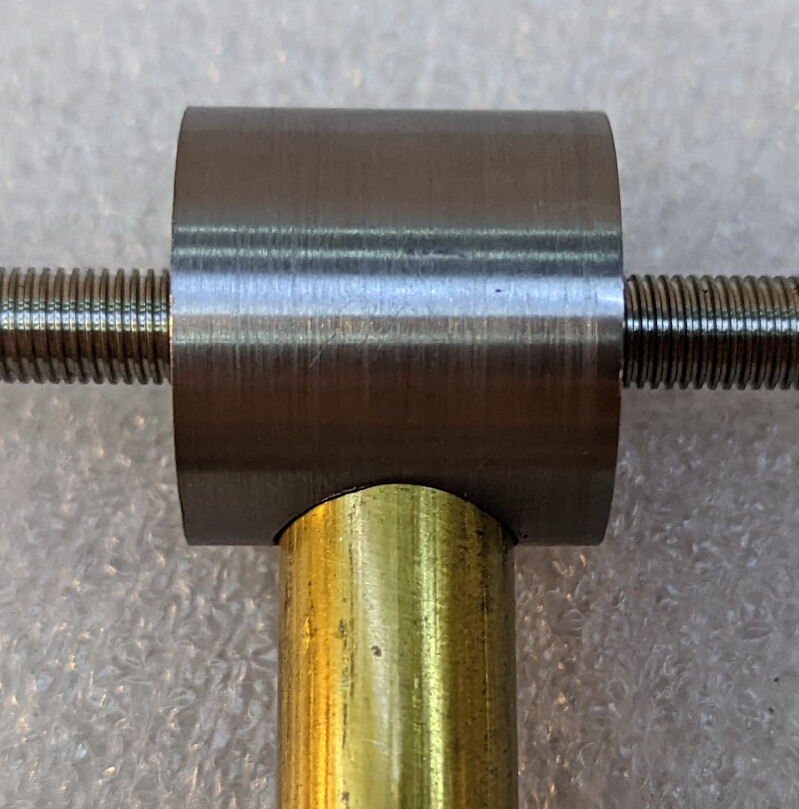
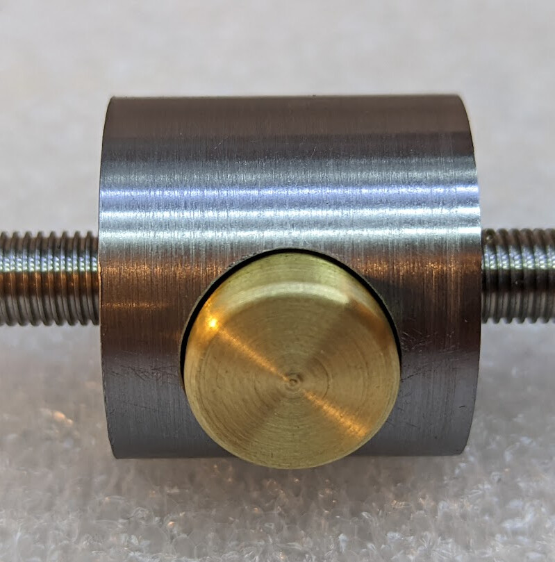
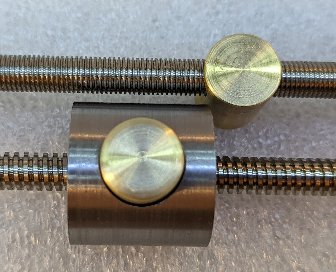
Here’s an example of it set up for the non-standard, fine-pitch TR 8 x 1 rod and tap that I bought:
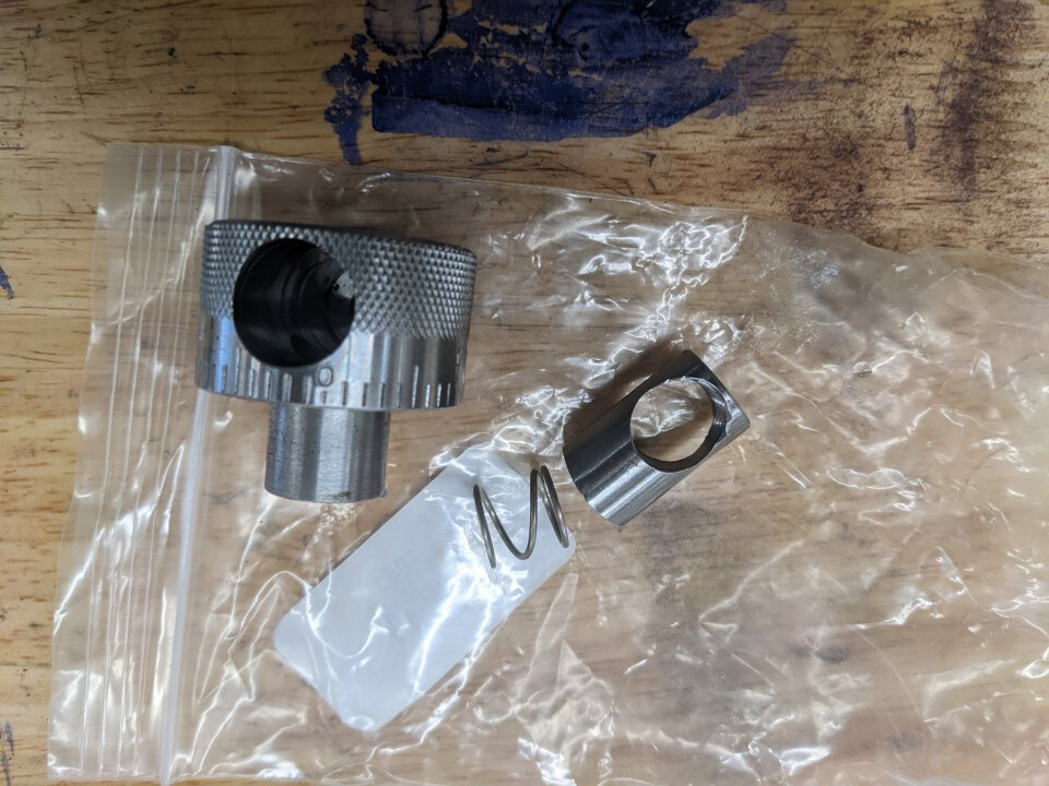
Of course, after I worked out that design and posted it, I found a picture that showed me that that the commercially-available nuts are much simpler. A single piece knob, a round plunger with a hole, and a spring, and the button is captive only by the rod threaded through.
This allows them to be narrower; no need for the extra diameter from a separate shell. On the other hand, getting extra thread engagement requires either a larger total diameter or a racetrack button and corresponding hole.
If I had heard the joking term “educated nut” (it has graduations printed on it, “graduated” → “educated” sigh) I could have found these pictures faster.
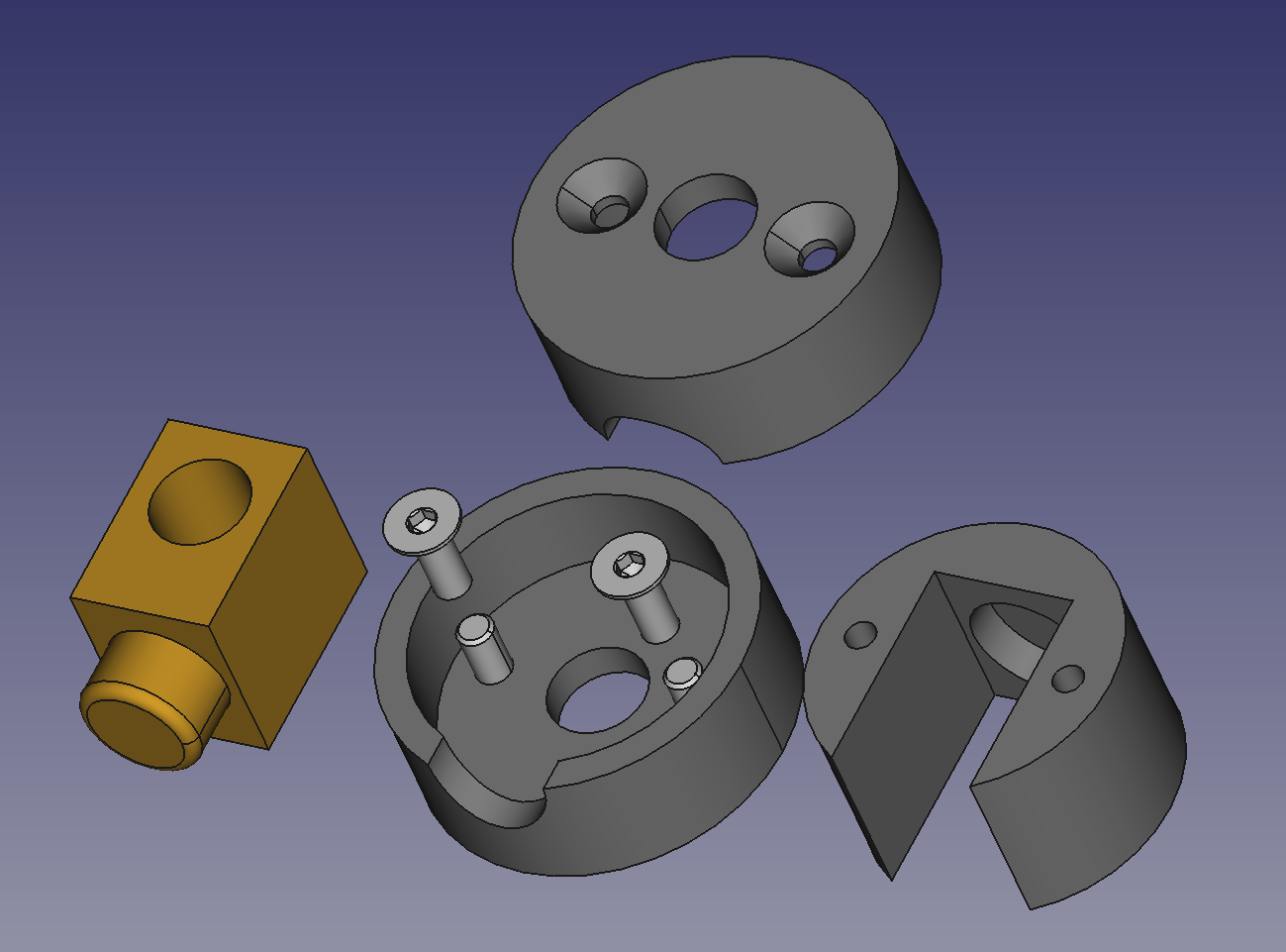
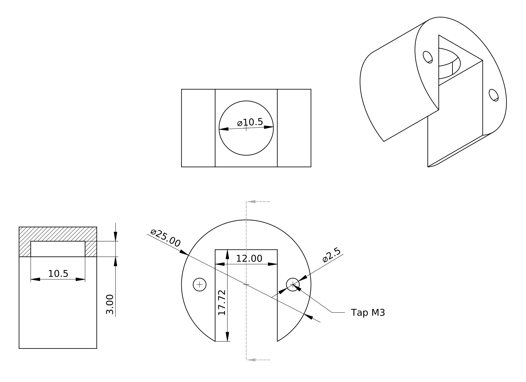
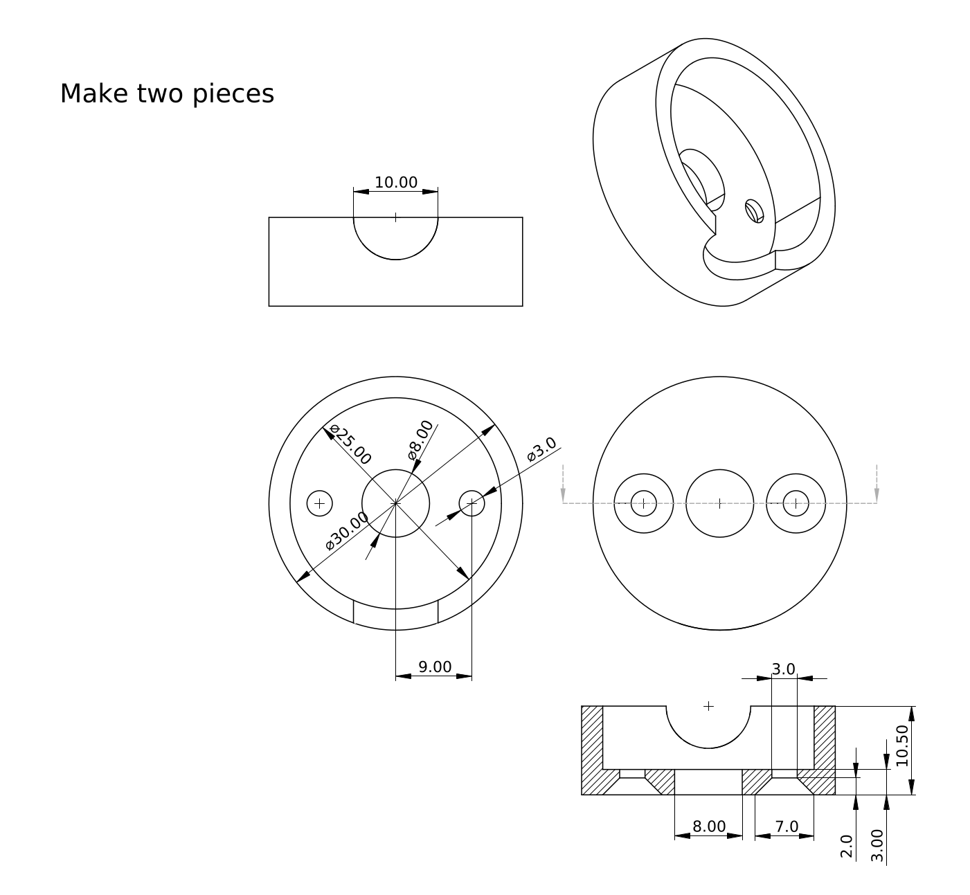
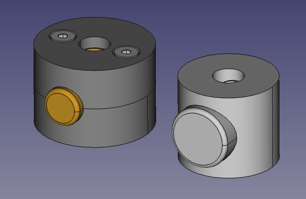
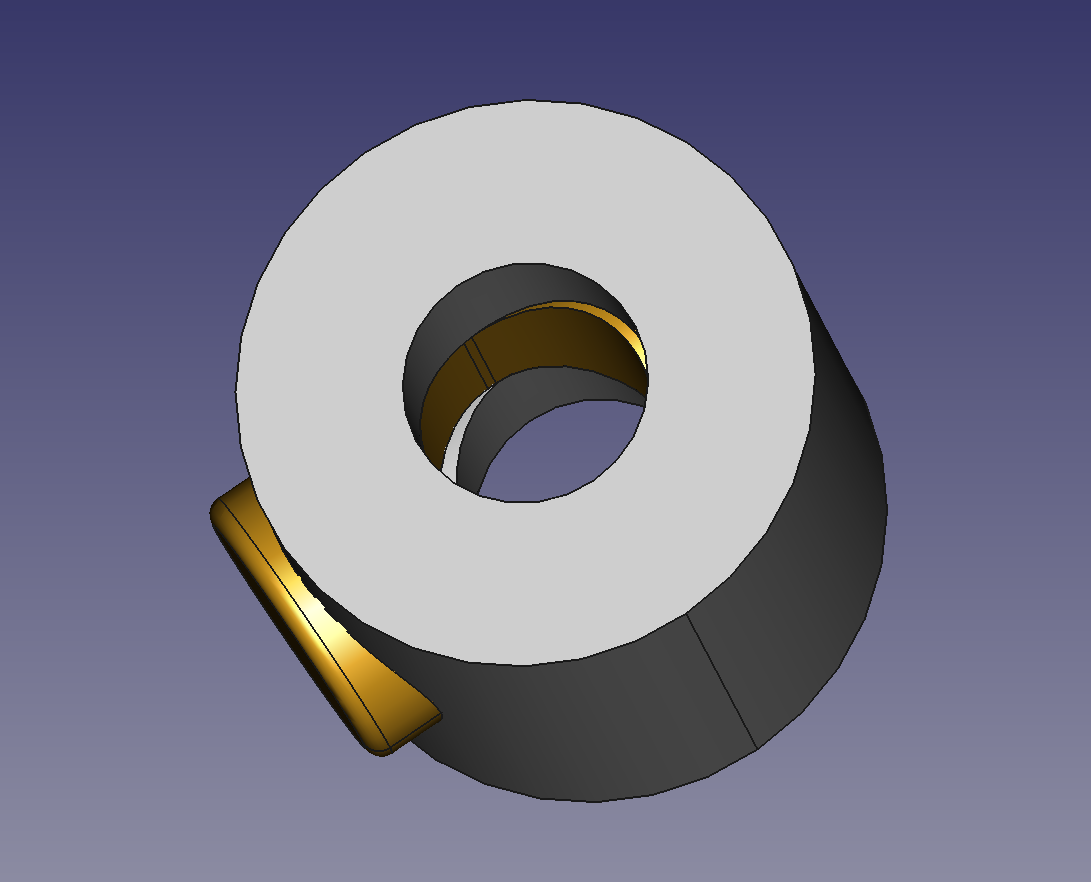
I haven’t yet made drawings for the simpler version that more closely follows the model in the picture I found, but I’ve created a parametric model of that simpler version. I’m doing some things different from the commercial unit. In particular, the commercial unit has an asymmetric collar for the threads to bear on; I’m using the same approach as the complicated nut of having three threads worth of contact at both the top and bottom in my simple version. It’s symmetric and I like that.
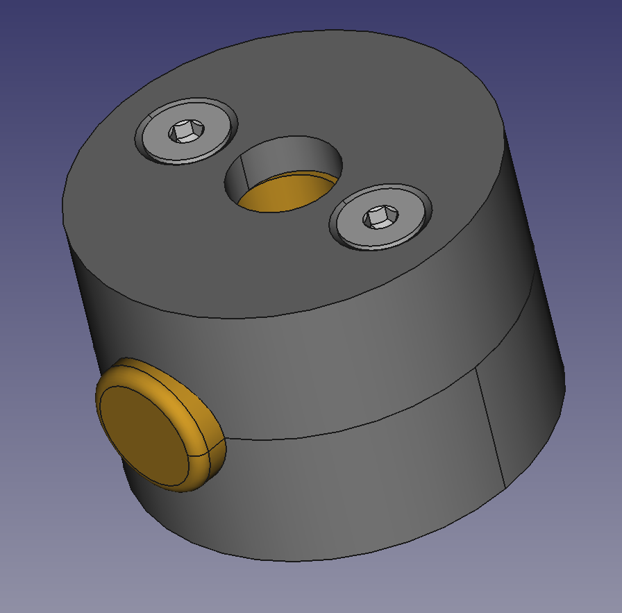
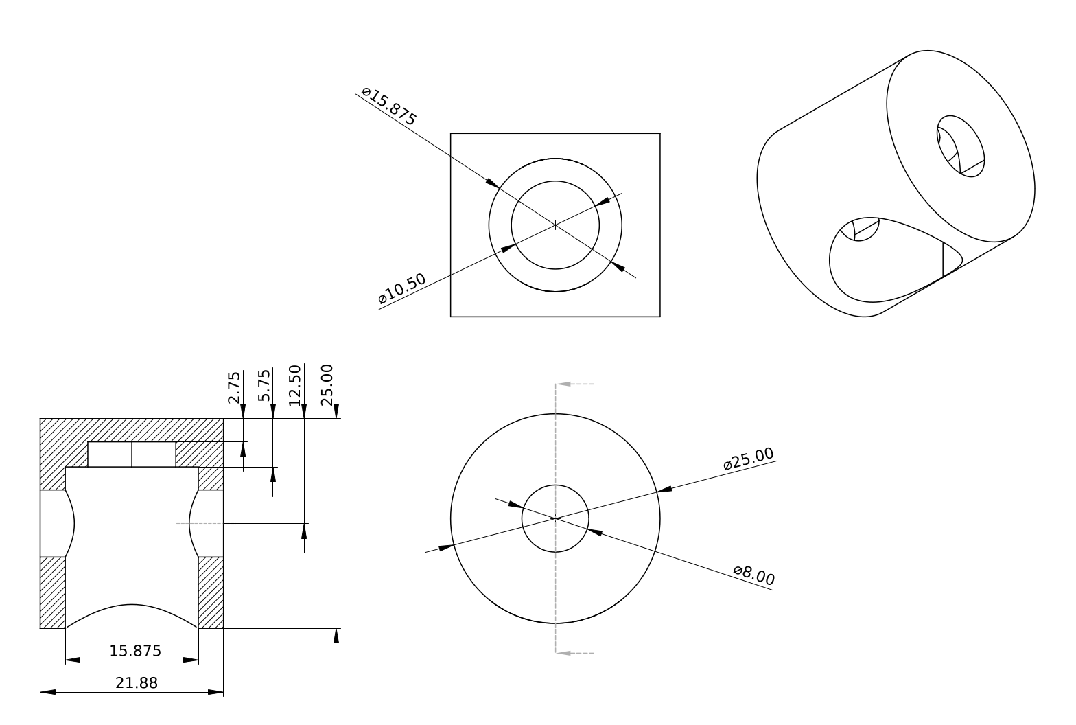
Here’s the model with 5/8" stock for the button and a 25mm nut body (a skim pass on 1" / 25.4mm stock). The outside diameter is actually not a critical dimension; there’s plenty of room for the spring. This uses the same spring as the original, and in fact is driven from just a few new parameters in the spreadsheet.
My weird complicated nut might actually be useful for the 1mm pitch because I can make it arbitrarily taller for more thread engagement without making it thicker, and 1mm might need that to stay put.
The normal nut should be fine for 2mm pitch or even the classic 1/2"-20tpi thread in between the two metric pitches.
In this one, as in the commercial unit, the rod holds the button captive, which should be fine.
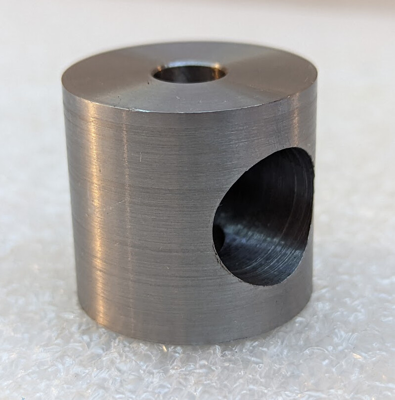
Got to work on the nut. I decided to use 1" stock and leave the rough finish on the outside, as an aesthetic choice that forced me to recalculate depths slightly. I also decided to make a single nut body long enough to accommodate both the 1mm and 2mm lead screws. After cutting a piece and facing both ends, I drilled it out to almost 8mm — 9/32" — and then drilled it through with an 8mm end mill. Then over to the mill.
I realized that I didn’t have a great way to fixture it, so I put it up on parallels, found the middle, milled a flat face on the top, and drilled a pilot hole.
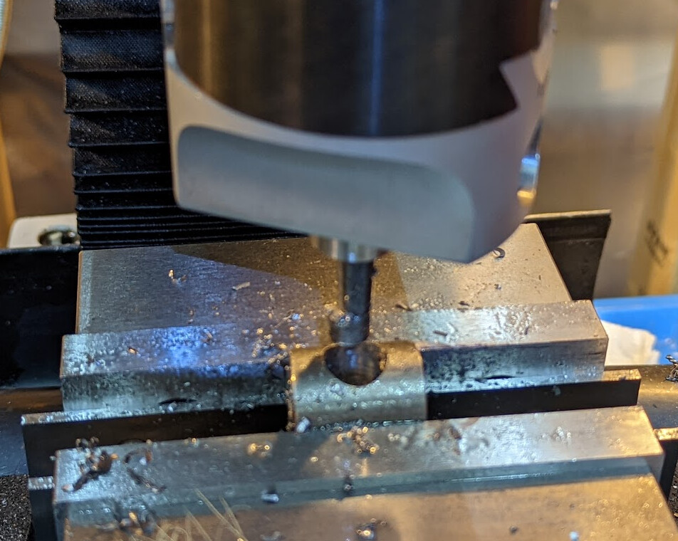
I don’t have a 5/8" mill to plunge, so I pulled out the boring head after milling it out 1/2" so that the boring bar could fit. (I actually milled it to 12mm oversize for the spring pocket.) Interrupted cuts are a pain.
Cutting through the hole in the middle meant that it recut chips a lot. I stopped frequently to clean them out, and used copious amounts of oil as I went to help it flush the chips out.
I haven’t yet decided for sure what scale to engrave. I’ve thought of doing coarse marks on one end and fine on the other. At about 25mm diameter, I have almost exactly 80 mm of circumference. I’m thinking:
One end with 20 graduations, one every ~4mm. That will give me .05mm per graduation with the 1mm lead screw, and .1mm per graduation with the 2mm lead screw. Major lines every fourth line will give me 0.2mm / 0.4mm per major line
One end with 50 graduations, one every ~1.6mm. That will give me .02mm per graduation with the 1mm lead screw, and I can probably visually split it to get close to 0.1mm. (I don’t even care that this gives me 0.04mm with the 2mm lead screw because why would I care about 0.04mm?) Major lines every fifth line will give me 0.1mm / 0.2mm per major line.
6mm major lines and 3mm minor lines sounds about right.
I wouldn’t want to try to go finer than 50 divisions because of leaving the surface rough. If I hate that, I guess I can make a new one, skim the surface clean, and make it a larger diameter. I’ll want to leave space for that when I design the stop plates for the mill…
I think I’ll use a v-bit in the mill to scribe the lines, and then fill them in with black paint to make them more visible. The alternative to to blue the surface and then leave the scribed lines bright in a nearly-black surface. But I’ll make a plunger before I invest in cutting 70 tiny lines with the dividing head.
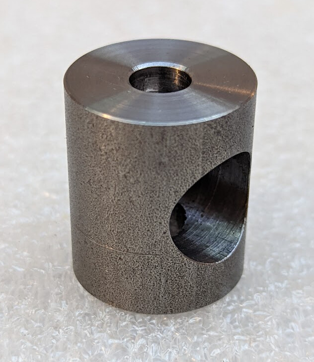
Sadly, it doesn’t function, because I did something wrong while centering, and the hole I bored in the side is a bit off-center. This means that I can’t actually use this one, it’s just decorative. For weird values of decorative.
However, the half-threaded nut itself works. I can run it up and down the rod on the smooth side of the hole, but the threaded side engages well. So starting over and making a new set and taking more care to center the hole should work.
I think that my fixturing was not good. If I make the whole nut on the stock and then part it off, it will be easier to fixture. I started by cutting off to near final length on the bandsaw and I think that gave me challenges that I didn’t actually need.
Also, the unfinished outside I thought would look nice just doesn’t. I’ll at least polish it up with scotchbrite if not skim it smooth for the next one.
As long as I’m making a new one, I might start with 1.25" stock for the nut instead of 1" stock. That’s almost exactly 100mm in circumference, and it turns out this one feels a little small. That might tempt me to try 100 graduations on the fine end.
I haven’t had a chance to use FreeCAD’s draft workbench since I started trade school where they teach blueprint reading, but seeing your drawings reminds me that I’m excited to give it a try with new knowledge.
Draft workbench is overall pretty good, and I found it easier to get what I wanted than when I tried F360’s a few years ago for comparison. The latest version has a lot of enhancements over even a year ago; like one-click stacked horizontal and vertical dimensions. I wish that it did multi-select the way the sketcher does (not needing to shift/control click to add items for multiple selection) but I can put up with it. I like that as an amateur I can leave off the engineering data block that I would ignore anyway by providing my own (blank) template and use that space for drawing.
It does get slow in a few cases, like when projections turn circles into b-splines, and FreeCAD will sometimes stop for a bit while it’s processing that, but that’s an area of active development right now, and it looks like there are now multiple developers involved if I understand correctly.
It also is a bit fragile regarding design changes. It’s not just the topological naming problem (for which they are finally merging realthunder’s solution, yay!) — merely changing sizes sometimes makes it lose track of dimensions. So my drawings for this nut sometimes lose a couple dimensions when all I’ve done is change parameters in the sheet that drives the design. I’m curious whether this will also improve as the TNP fixes land, though.
I started over. This time I centered directly on the stock; previously, I centered on the vice jaws with a collet holder in them that I thought had low runout. Maybe I did a poor job of centering off the jaws, or maybe the collet holder has more runout than I thought. I measured repeatedly as I went to make sure I got it right this time. I also used a piece of 0.001" shim stock as a feeler from the body of my edge finder with the mill stopped instead of watching for the bottom of the edge finder to kick out. I kind of like this method and might use it more.
I started with 1.25" 1215 stock and cut it down to 30mm diameter. Just for fun and practice, I hit within .0005" of 30mm for the diameter. I know that’s a weird way of expressing that. I have an imperial lathe without DROs, so I set the micrometer to 30mm exactly, put it in incremental mode, change it from metric into inches, then measure difference from target as I go, and the measurements translate directly into marks on the lathe dials.
The 30mm wide nut (about 28mm tall; you’d think I would have just made it square…) has a much better feel. And I might be crazy enough to try 100 lines on the fine side.
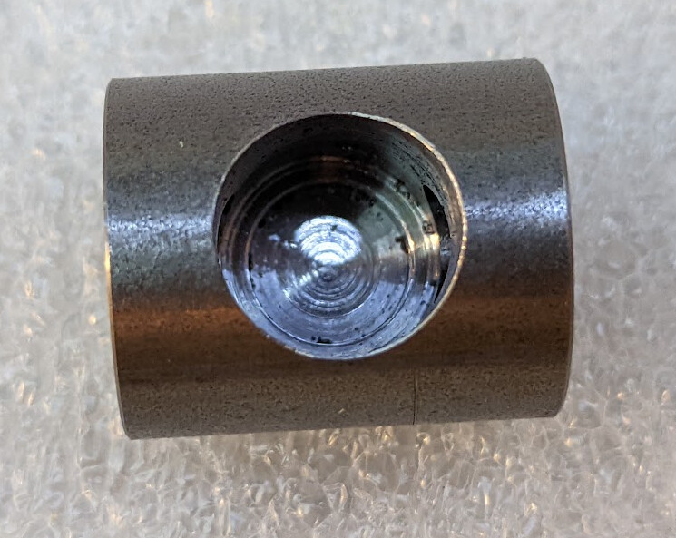
This picture was before I noticed that I needed to fettle that large hole some more. I tried to use a diamond needle file to work the edge until it was comfortable to the touch, but ended up with a deburring tool. I also had to use that to clean up the insides of the intersections of the holes. That was a slow process.
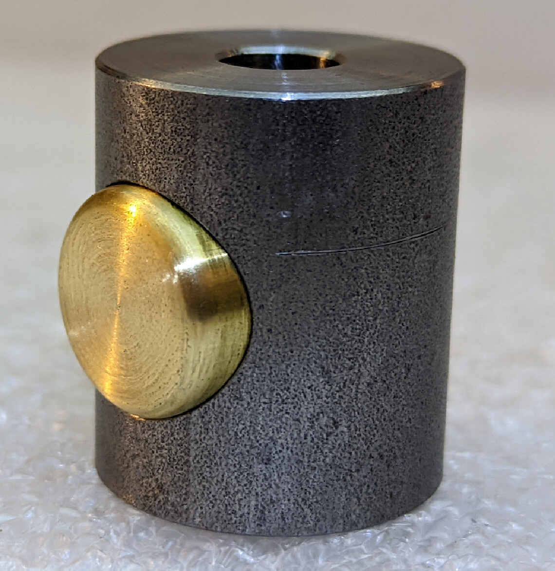
Then I made a new plunger, taking the same care to center everything perfectly. This time, before I cut it off to length, I made sure that the screw would fit through — if I had messed up again, I could have scrapped less material to start over another time. But it fit nicely!
I cut the plunger to length, put a light fillet on the outside with a chamfer tool and a file to round it off, polished it lightly with scotchbright, and it’s ready for engraving.
I don’t think this is true. The first normal nut I made was with the 1mm trapezoidal lead screw, and it seems quite solid. So the weird complicated nut is probably just a bad idea. The button is small because it’s limited by the width of the slot, and it would be less comfortable to push.
What skills I have are thanks to YouTube machinists and a very tolerant wife who has encouraged the new hobby.
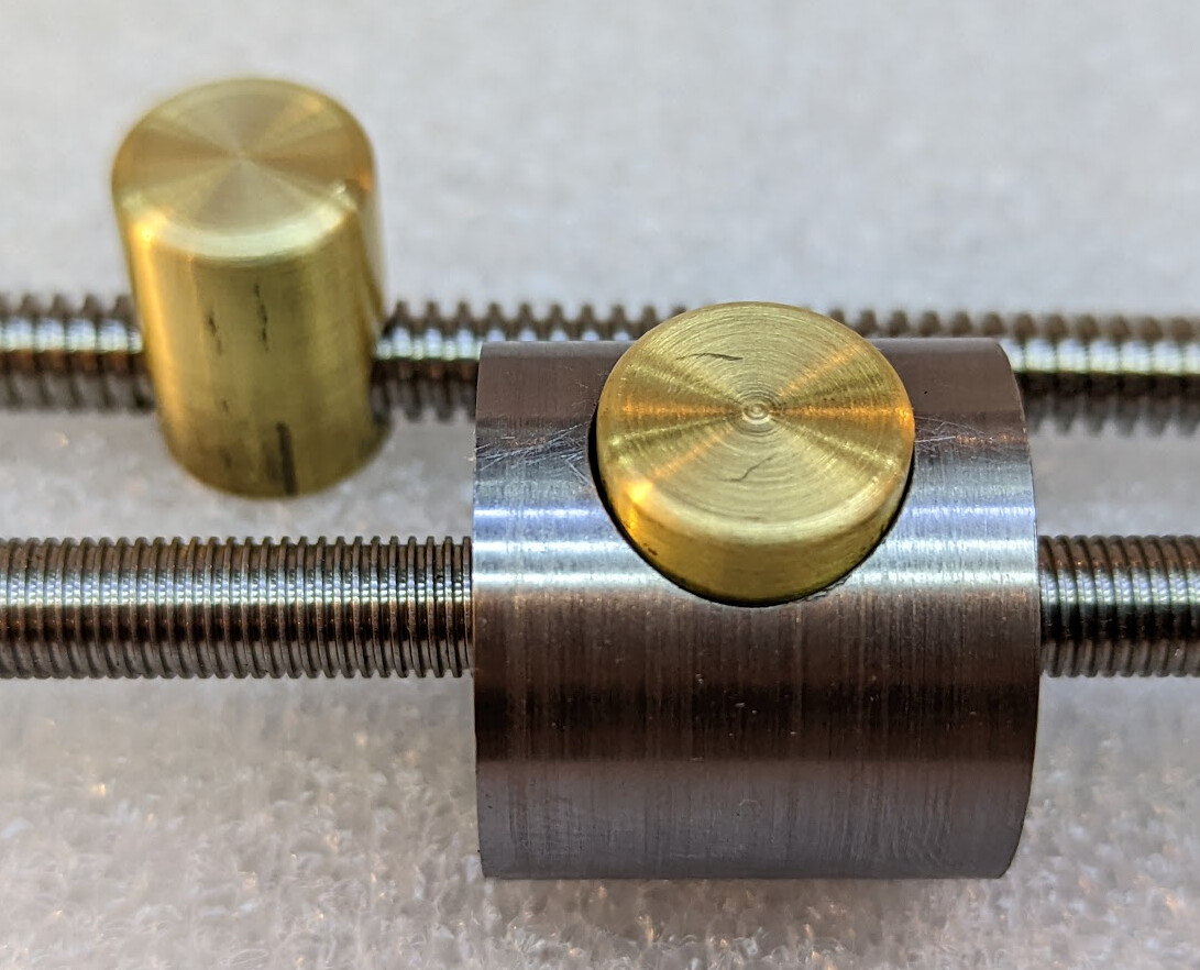
Also, plenty of mistakes; see here that by careless measurement I made two scrap parts on the way to this so-far success. I’m a little bit terrified of one wrong move while engraving the gradations on the nut…
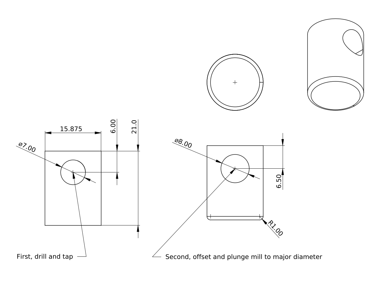
I want a single nut body with two buttons, one each for TR8x1 and TR8x2, so I can use two separate rods depending on what I’m working on; probably TR8x2 for most work, but TR8x1 for higher precision work. They have the same major diameter (8mm) so this shouldn’t be a problem.
I did the TR8x1 button first, and intentionally made it tall enough to support three thread lands of TR8x2 so that one nut could work for both rods. However, when I bored out the body, I didn’t think about the extra half millimeter of travel that the TR8x2 nut would need to disengage the threads when I made a TR8x2 button. Rather than try to set the nut up perfectly to bore out another 1/2" of depth, I just took half a millimeter off the spring end of the new TR8x2 button so that it could depress enough. I also milled a slot to make it easier to move when it is disengaged.
The TR8x2 tap should follow a 6.1mm drill. I excitedly remembered that I just bought a metric drill index by 0.1mm increments and pulled it out, to discover that it is a 1-6mm index by 0.1mm. 6.1mm was not in the set. There isn’t even a great match for 6.1mm in letters, numbers, or imperial fractional sets either, so I just went with 6mm.
The Shop-made spring-loaded tap followers came in handy for tapping. The tap was a little tight, but I backed it out and cleaned it several times and did no damage.
I have updated the design to have only the normal simple nut, not the weird complicated nut. It was getting hard to maintain a single set of parameters that controlled both sets correctly, and with all the extra parameters it was just a distraction for anyone else who wants to try this. It turned out that in cleaning up and simplifying the parameters, I found a bunch of improvements to make in the parameters, both in terms of the forumulae and the names of the parameters.
I also found and fixed one more bug in the model when looking at the standard 1/2" 20TPI size — the size that you can actually buy, and don’t have to make.
That’s actually a fairly fine thread, 1.27mm, so closer to the fine-thread metric than the coarse-thread metric nuts. If I make one of those, I’ll also have to make a new nut body as well as button, of course. I’m not sure I care enough about imperial to make the imperial version of the nut, graduate it, and work out how to modify the stop hardware to fit two sizes of stop rod. Or, rather, I’m really rather sure that I don’t care enough about imperial.
Now I just need to steel myself to graduate this nut body, and design the stop hardware that it is meant to bear against.
I appreciate the time you took to put this out there. I’m trying to design one for a 1" x 8 thread and am running into issues. The nut “insert” seems to work fine, it slides up and down the rod and the threads engage well when pushed. The “body” is a very tight fit to to the rod allowing it to slide up and down also with almost no extra play. However, once assembled, it works…but anything tighter than hand snug and the threads push the nut back in the body and the tension releases. I’ve made a few variations, some better than others, but I just can’t figure out how to keep the threads engaged while tightening. Any thoughts or ideas? I’m using a hefty spring that takes quite a bit of strength to push the nut in enough to slide it… I’m not sure what else to try. Would love some advice!
I’m using trapezoidal threads. These have a 30° pitch cone for the metric threads I’m using, or for imperial ACME threads, a 29° pitch cone, compared to 60° (or 55° for whitworth) pitch cone for screw threads. This reduces the possibility to back-drive the button to disengage the threads; it means that they won’t easily drive out that way. I was worried about the 1mm pitch/lead screw not having enough engagement area, which was one of the reasons that I made both 2mm and 1mm pitch/lead screws, but I’ve never had it jump even with the 1mm screws, where each land has less than .5mm of contact maximum.
That said, the normal units have 20tpi screw threads. But maybe they don’t get pressed very hard in use? I admit I’ve never used one, so I don’t know how hard it is to overpower them. If you are using a drill press or mill with one installed, I don’t know whether cranking down hard on the quill downfeed will cause them to skip threads.
1"x8 seems to me like a very coarse thread for this application. The whole point of the push-button is to let you make rapid coarse movements linearly, and small fine movements radially, right?
Machinery’s Handbook lists 1" 5tpi and 5/8" 8tpi ACME standard threads, but not an ACME 1-8 standard, as far as I can tell. I do see a screw and nuts and a tap available for ACME 1-8. They aren’t cheap.
If you don’t want to change the thread form, and the spring is a strong as you can take, I guess you could change the height of the nut. The more (half-)turns you have on the nut, the more friction between the faces, and the harder it will be to drive the button in.
Or perhaps you could add a locking mechanism that you can engage to lock the button/insert in the engaged position. I can imagine all sorts of ways to do that, none of them obviously both functional and simple.
Thanks for this - it gives me some ideas I hadn’t thought about yet. My case a is a bit different, both in application and manufacturing. I’m building a jig to center a drum along a 4’ threaded rod. I have a scissor lift type mechanism that spreads out to grab the inside of of the drum shell in 3 spots. I’m making a push button nut so when I change out drum sizes, I don’t have to unthread the full 2 feet or so… I do believe the static force on the nut is good (not sure that’s the right term, but I could tighten a metal nut against it without it backing out of the threads… but using it like a nut, spinning it to tighten/extend the scissor lift, and the insert pushes back on the spring with anything more than slightly snug (which isn’t enough… I need only firm hand tight). I’m using UNC thread, just typical 1" x 8 threaded rod, not ACME… really just for availability and costs (and I’d also prefer the 8tpi over 5 as this feeds forward as it spins to round the shell, so lighter passes of 1/8 per rotation I think works good… I’d imagine ACME threads would do better in this instance (at least for locking the threads). As for manufacturing - I’m designing this in Solidworks and 3D printing out of a PC-CF (polycarbonate with carbon fiber strands) It’s a very durable material. I’ve done some destructive testing to make sure I had good thread engagement, and the threads fit the rod perfect. I’ve printed threads before, down to 1/4" NPT that I tightened with a wrench and was watertight with this same material… so I know it can be done. I’ve taken apart a quick adjust C clamp that has this same sort of mechanism, but it operates quite different, and wouldn’t work for my application. I have a full 6 threads of engagement, so it’s already quite large. I have an idea to add threads to the front half of the body, and to the back half of the insert so the spring opens to the OD of the threaded rod, but then there is engagement from the back of the insert that pushes against the front of the body which could aslo be threaded… this would at least give close to double the engagement, almost 360deg… but I can’t visualize if the same issue would happen… (it takes 2 hours to print and costs less than 1 dollar in material, it’s really just design time at this point) I may try that, and use your idea of a locking mechanism if that doesn’t work. I do believe I could easily put a small pull pin hole through the body and insert that could lock it in place once I get it close to position…or perhaps a set screw from the back, right in the middle of the spring… if I think about it some, maybe I could even do something unique like a slide that pushes and locks as to not require a tool to disengage the threads… Well… that’s a lot… the main point here is that you game me some things to think about and try… I very much appreciate it!
Given your use case gives you access wherever you need, a set screw through the back of the case to lock the half nut in place seems to me like the obvious mechanism.
When you don’t need precision adjustment, there’s another kind of quick-adjust nut, which is two halves pressed together with spring pressure — think like a clothespin with threads. Here’s one example (though not sized for your use):
A design like that could have a cam-over lock on the back side and be very easy both to slide and to lock.