DIY Depth stop for my mill

The more machining I learn, the more I wish I had a depth stop on my mill. Real Mills have a depth stop, usually with a graduated nut (“educated nut” har har) that has a push-button release to slide quickly to near the right place and then rotate for fine adjustment. (Many of them, though not mine, even have power downfeed and automatic return when they hit the depth stop!)

I spent a long time planning this, but it’s finally just about done.

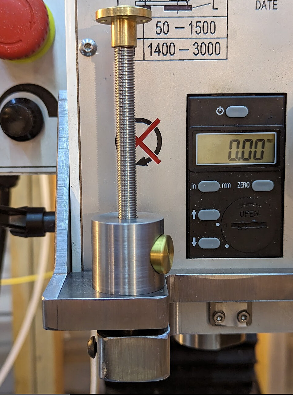
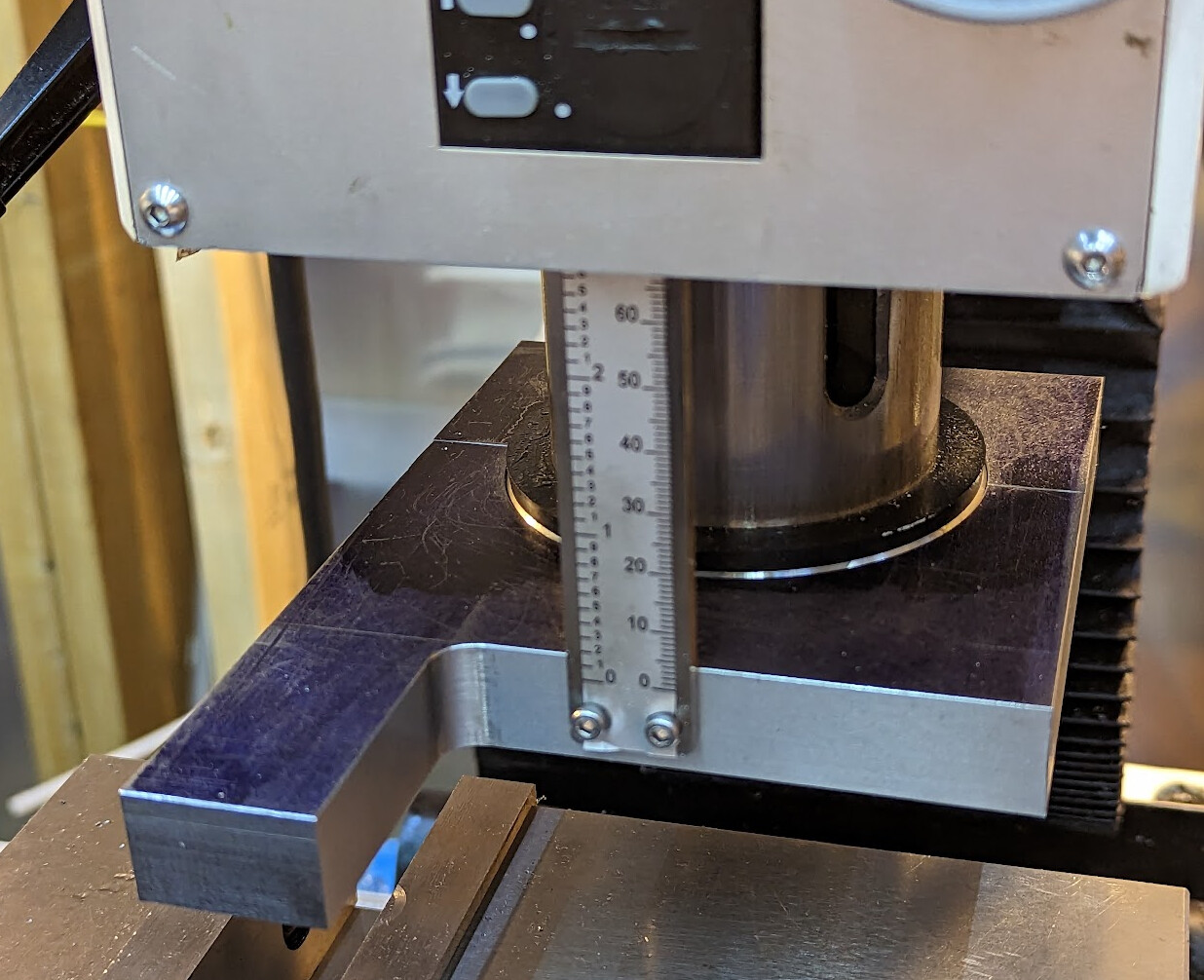
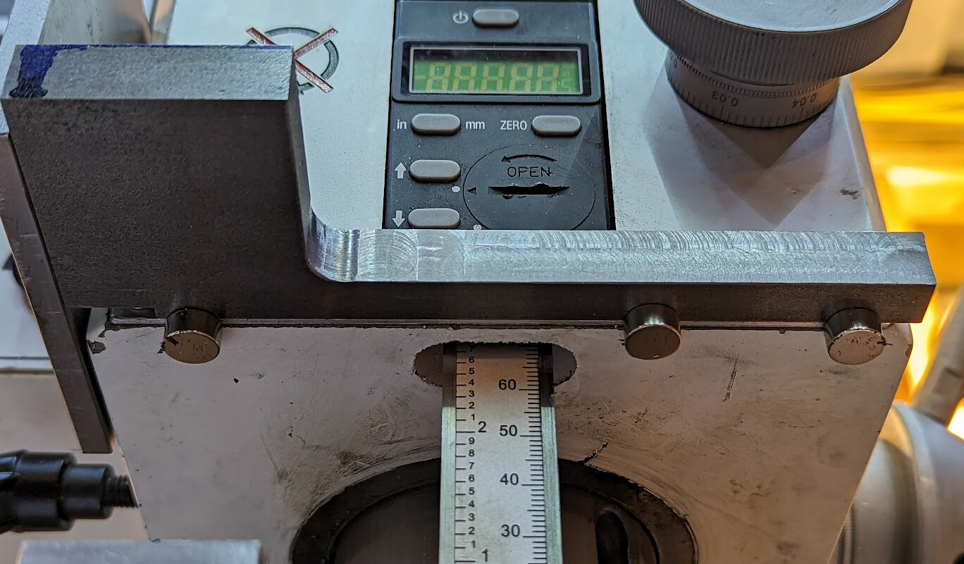
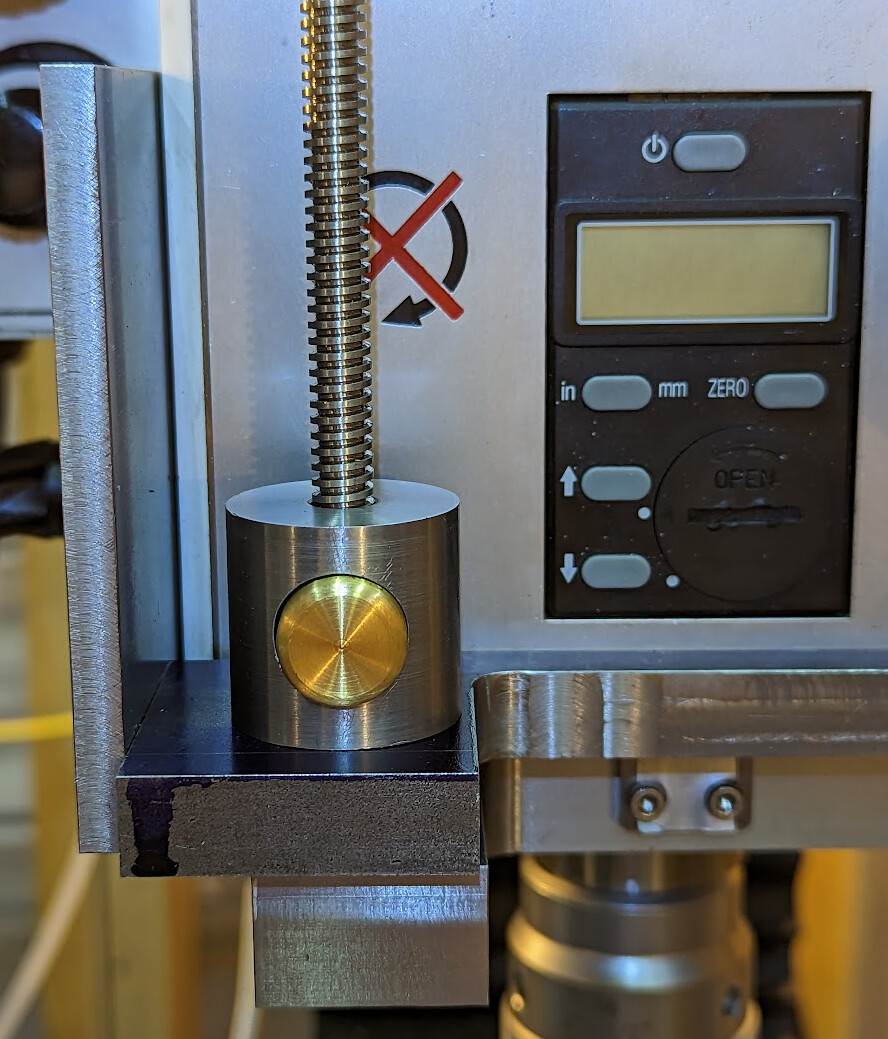
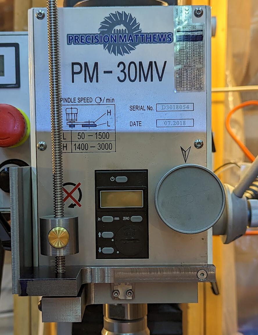
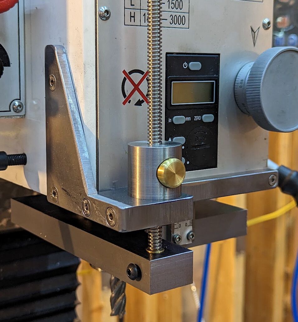
When I lower the quill, a plate connected to the quill pulls down the screw until the nut with the button in it hits the plate connected to the mill head. Within the precision of the quill DRO (which reads 0.00mm in the picture above), depths are repeatable ±.01mm. The DRO is probably itself ±0.01mm so that’s a total range of perhaps as much as 40 microns in theory, and probably closer to 20 microns. Just locking the quill with the kipp handle on the side moves the quill down about 30 microns, so that’s pretty much as good as can be reasonably expected for this mill.

I started with the nut. I knew that nuts with buttons existed, but had no idea how they worked, so I came up with a really complicated design which I fixed when I learned how simple commercial ones really were.

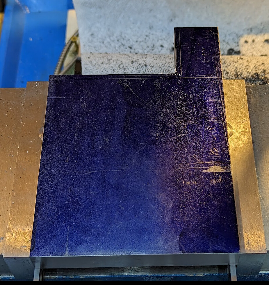
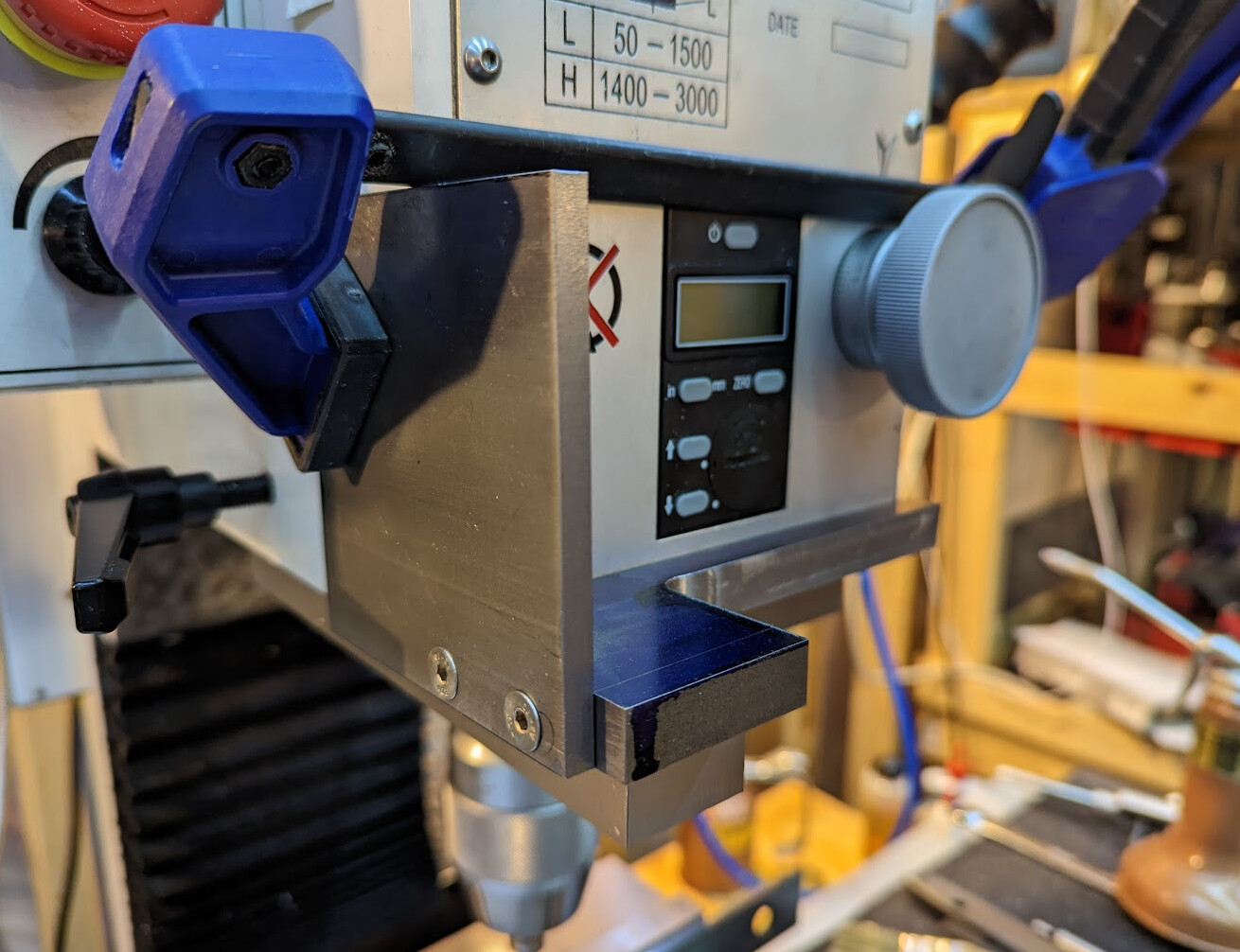
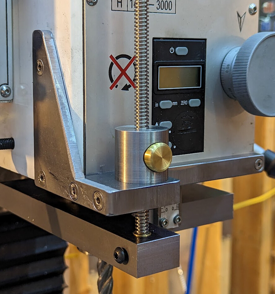
I noodled around with slightly different designs in FreeCAD for months. I finally ended up with this design, which I was able to execute without drilling any new holes in the mill. (I’m not against new holes per se; it was just a fun design challenge.)

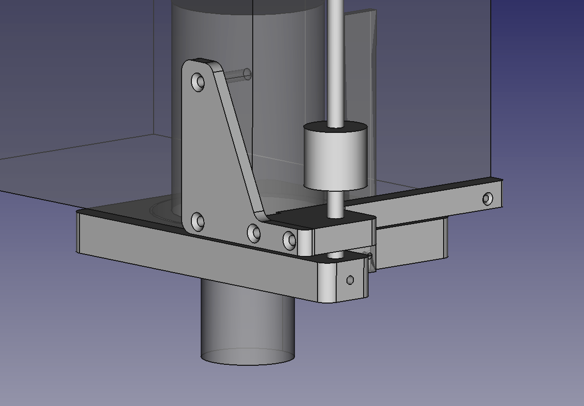
That’s recognizably similar to what I ended up making:

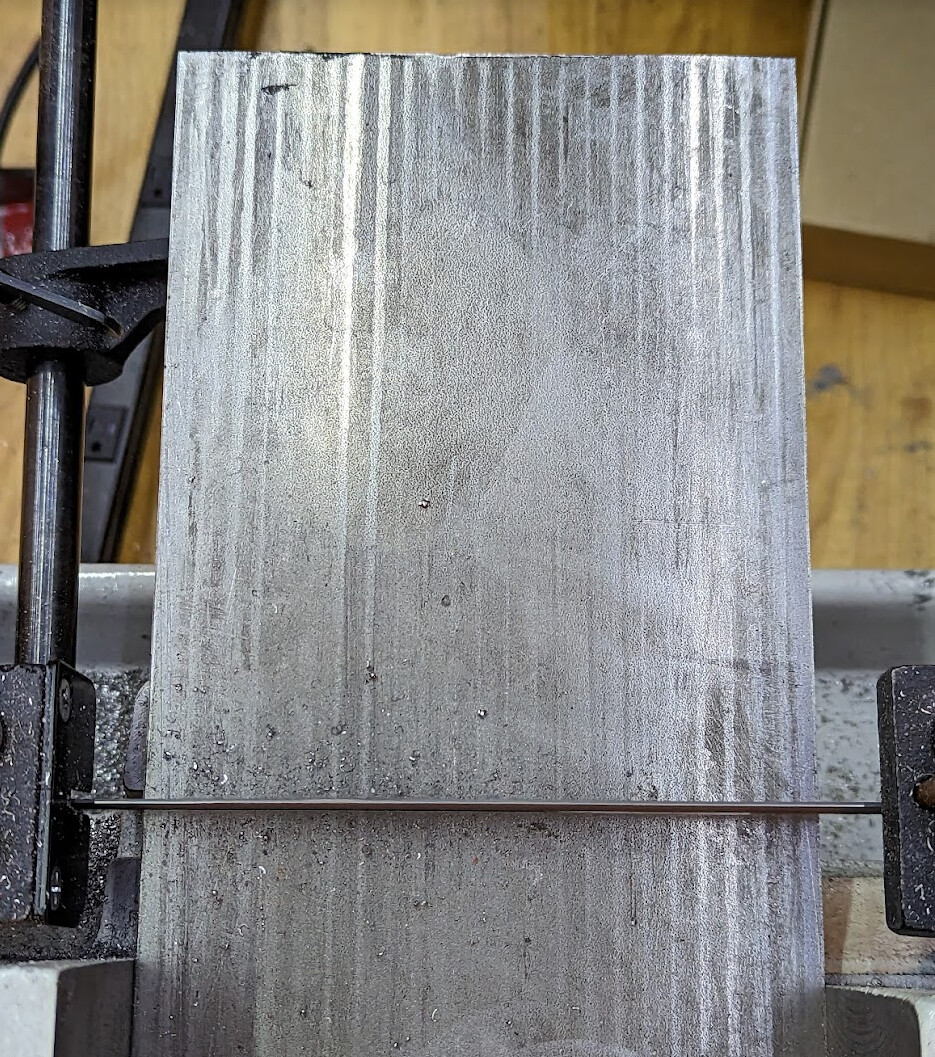
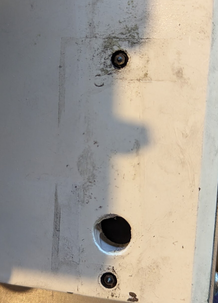
Three of the screws go into existing holes on the mill. Those I located using transfer screws, and then drilled the locations.

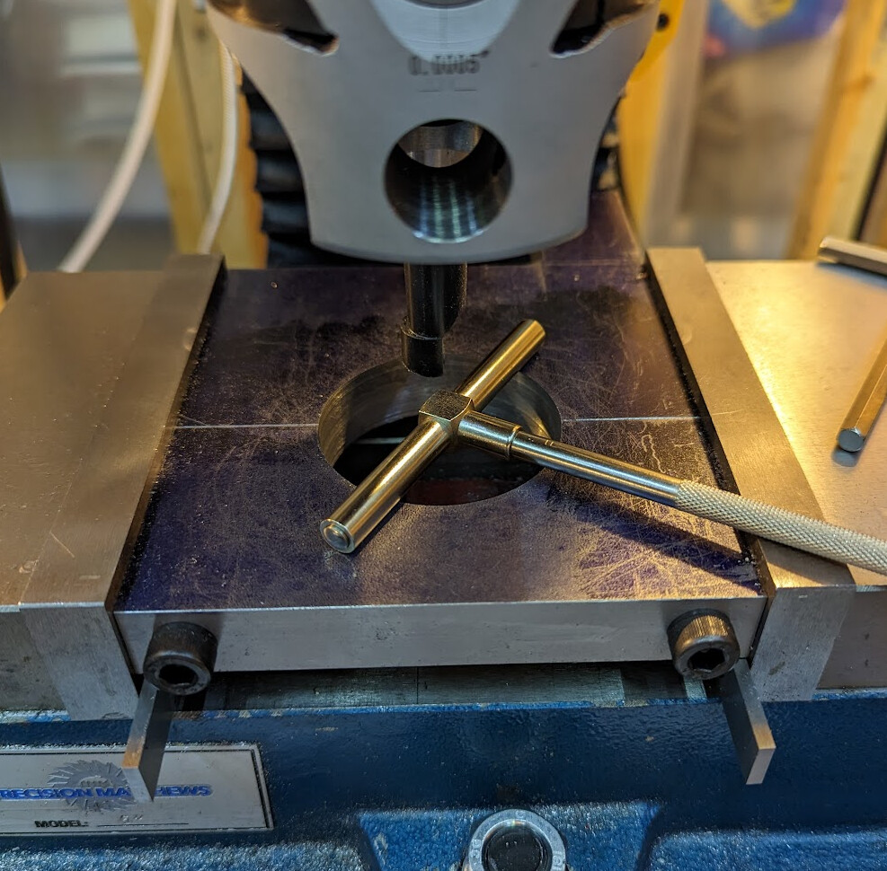
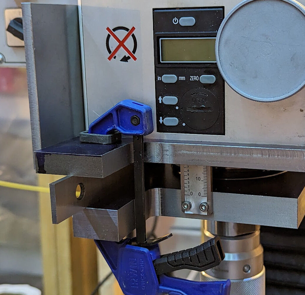
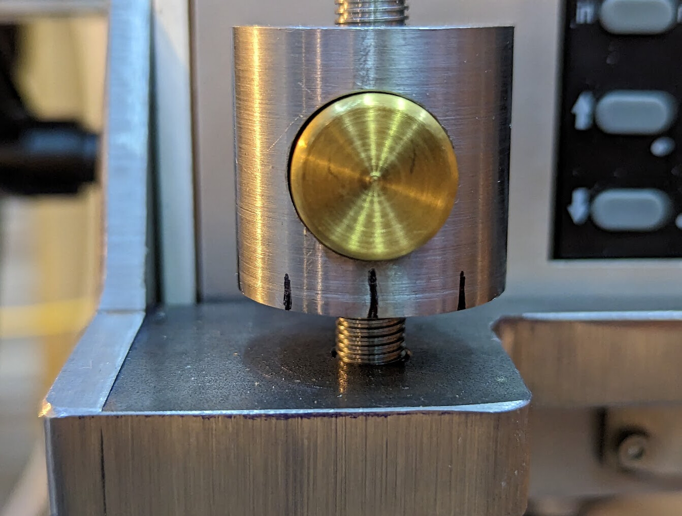
I finally decided to graduate the nut with sharpie to begin with and see whether 10 graduations are actually enough. I’m just not ready to cut the metal until I see how I really use it in practice. I don’t have any references to line the graduations with anyway, so making it super fine just isn’t going to help. I think.

If a normal graduated nut is an “educated nut” I guess this one is still in elementary school?

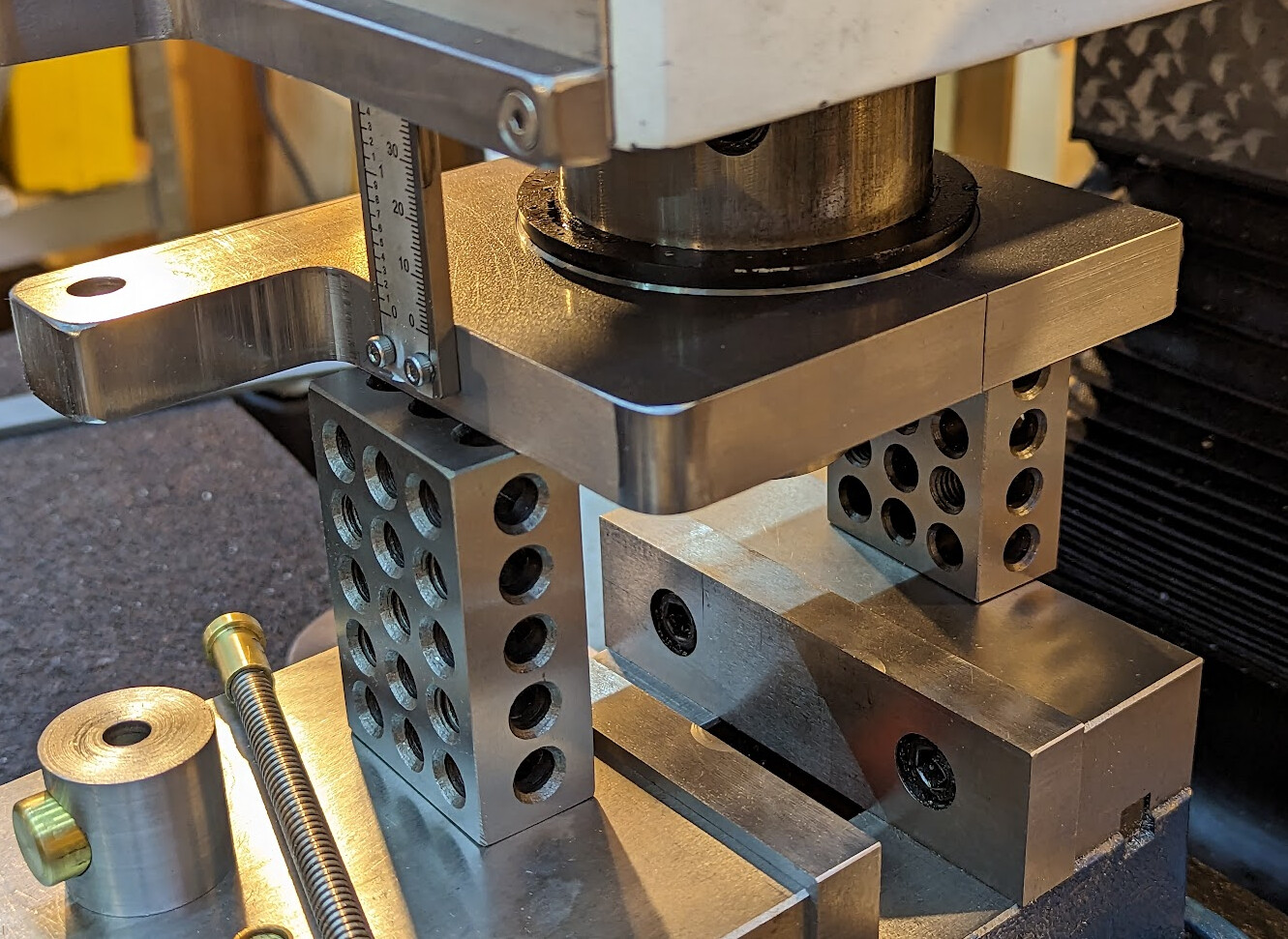
I did make both the 1mm and 2mm lead versions, and I can swap back and forth if I want to:

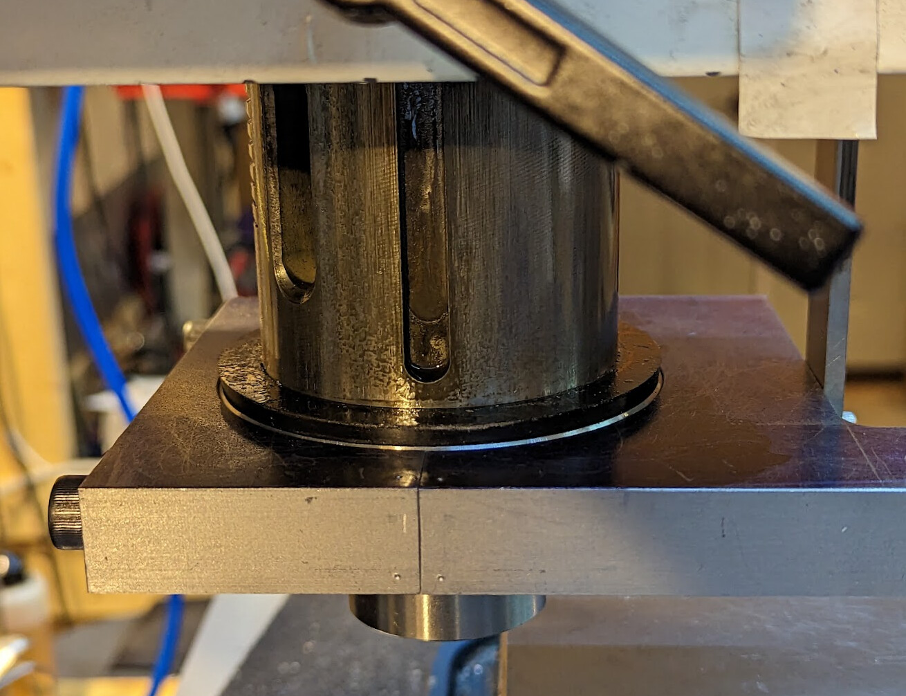
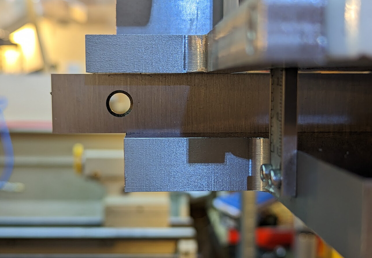
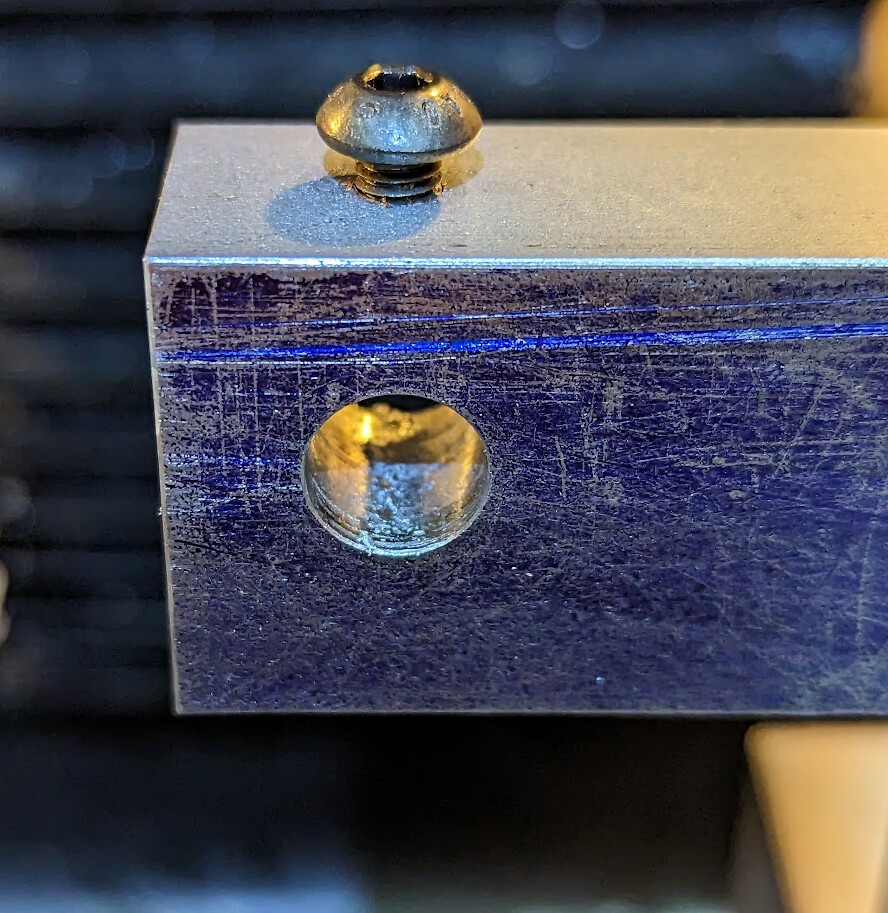
I am putting the lead screw nuts that came with the screws on top just to keep the graduated nut in place. I’m not sure whether I’ll keep that up; it’s just an idea. The screws have brass round nuts at the bottom that register in a shoulder in the hole in the quill plate. They are held to the screws with loctite and are a pretty tight fit to start with. I can replace them if the fixing screw in the side chews up the brass too much, but honestly that will happen only if I actually end up swapping out lead screws, and at this point I’m expecting that the 1mm lead screw will get almost all the use, so probably it will just stay in place.

5 Likes

The quill plate was quite the job. I started out with a 6" wide piece of 3/4" cold rolled steel plate, not quite 8" long. Glad I wasn’t trying to cut that with a hacksaw!

I scribed some layout lines on the top and cut a chunk out.

If I were doing this over, I’d probably wait to cut that chunk out. It made it hard to drill the holes in the back for the M8 screws that clamp it around the quill.

I drilled the holes to tapping size in the back, sliced it through, cleaned up the sawed faces to dimension, tapped the bottoms of the holes, drilled out the tops of the holes to clearance diameter, bolted it back together, putting a few witness marks so I am not in danger of putting it together backwards, and started drilling out in the middle of the cut. Eventually, I switched to a boring head.

Sadly, I cracked the carbide face of the boring bar. I wasn’t going to get a precision finish that way. I mounted it in the four-jaw chuck in the lathe and finished boring out. The jaws that clamped side to side across the split were quite light to avoid boring the hole out of round; the jaws that clamped front to back were tighter.

I had to buy a 4" micrometer to measure the quill, and then I used the micrometer to make the hole a location fit.

I drilled holes to attach the quill DRO, and then replaced the DRO quill collar that came with the mill with this new quill plate. It wasn’t done yet, but the mill was usable.

Side view, with witness marks showing the matching side.

Initially, I had planned to counterbore for the screws in the back, but it turns out that being able to see the screws when loosening or tightening them is a feature, not a bug!

3 Likes

Of the three pieces of cold rolled steel I used here, one was 3/4", one 1/2", and one 1/4". I’d originally purchased the 1/2" bar for making a t-nut for my lathe QCTP, but the 3/4" and 1/4" I had to buy new. Now I have more stock for the next projects!

I roughed out the front plate and the side bracket and screwed them together, then clamped them to the mill head to see how they fit:

I also used strong magnets to hold the front plate in place while testing out placement:

Fortunately, I checked whether the quill plate and front plate were parallel before I did anything irreversible:

I ended up clamping them together across a parallel to locate them correctly:

I located the holes in the side of the mill with transfer screws I made from O1 tool steel. I hardened but didn’t temper them, and I guess I got lucky that the tip broke off rather than the screw breaking apart in the hole.

When I screwed it all together, it looked much better!

Setting the screw on top of the front plate, I was convinced this was going to work!

I used a transfer punch in the quill (because I still don’t own gauge pins) to make sure that the lines I marked were going to work when I drilled out the clearance hole in the front plate:

Then I used a transfer punch to mark where to drill the matching hole in the quill plate, into which to fix the lead screw:

I drilled the hole and counterbored the bottom for the flange in the lead screw round nut, and then put an M5 button head screw through the side to hold the lead screw in place. The positive stop is the flange on the lead screw against the shoulder of the counterbore in the quill plate; the screw just keeps it from dropping out.

Looking up from below shows the flange and screw locked into place:

The lead screw was too long and the bracket was still not trimmed and was in the way, but I was starting to see the light at the end of the tunnel. At this point, the stop was usable in a pinch!

I put the bandsaw in vertical mode, roughed out the bracket, and finished it on the belt grinder. Yeah, it looks a little rough, but it’s good enough, and I was getting impatient.

At this point, I used the depth stop to make A Mathematical Valentine's Day gift: Intransitive Dice and More intransitive dice: Machining precision mathematical toys

2 Likes

Today, I used the belt grinder to round off the corners and edges on the quill plate to make it more comfortable to use, and finally removed the dykem blue from the surface — kind of my way of declaring to myself that this job is complete.

When putting it back on the quill, I used 1-2-3 blocks to make sure that it was tram to the table and vice:

I cut the lead screws (both the 2mm and 1mm pitch versions) to length, installed the 1mm lead screw, and declared victory.

On to the next project!

4 Likes

Wow, that was an intense project!

3 Likes

I forgot to mention another important point: locating features.

The quill plate pieces are located to each other by the quill itself. But you’ll see five countersunk screws used; four going through the side of the bracket, and one at the end of the stop shelf. I used countersunk screws because a taper is a precise locating feature, and threads are not. This means that a screw head where the bearing surface is flat might move a little under pressure, which could reduce repeatability if it creeps a bit in use. The countersunk screws don’t need to be tightened to the point of worrying about stripping threads to be secure.

Many think of locating tapers as being more shallow, and yes when you have a machined locating taper it will be shallower. Typically steeper than 8° if it is meant to be self-releasing, and shallower if it’s meant to be self-holding. 45° is an extreme case of a self-releasing locating taper that happens to be cheaply available for screws. :grin:

Initially, I didn’t share the FreeCAD model here because it was more of a scratchpad than I like, and probably if someone else wanted to do this they would want to start from scratch and do it better. I didn’t even make an assembly; I just moved bodies into position to check whether a fit was possible. It’s easy to assume that CAD files are meant to be canonical; here they were filling the purpose of a napkin drawing (by someone with drawing skills), for the most part. Similarly, the drawings represent what I initially planned (e.g. the counterbores that I omitted from the quill plate and the counterbore that I added for the flanged round nuts that I made), and are done crudely, just enough for me to use for reference while making my own designs, never intended for others. But on reflection, I’ll share the files just in case they are useful as a starting point for anyone considering embarking on a similar journey.

StopCollar.pdf (36.9 KB)
StopPlate.pdf (16.4 KB)
Bracket.pdf (15.2 KB)
DepthStop.FCStd (308.9 KB)

2 Likes

Update after a month of use, in which I’ve been overjoyed to have this new feature…

So far, the 36° lines have been enough; really I can interpolate in half reliably which is .05mm and that’s all I really need. Turning the nut has been the hardest thing because of the smooth surface, so I think that putting engraved graduations on one side and knurling on the other will probably be what I want to do.

Then I’ll want to add an index line somehow. Still thinking about how to do that.

The top picture in the original post shows the nut that came with the rod on top. I put it there to keep from snagging my hand on the top of the rod while working the nearby controls, but it kept running down the rod from vibrations while the mill was running. I rashly put some thread locker on it to keep it in place, and now realize it’s going to be quite the pain to remove when I want to do the engraving and knurling. I guess I’ll get out the torch!

2 Likes