MeerK40t: new Laser Software for stock M2Nano

I wanted a more hackable and useable codebase than Whisperer so I built a new laser software package from scratch. It should, in order to stand a good chance, be better than Whisperer out of the box on a few different fronts.

  • Grid/Guides Scene Navigation.
  • PPI Power modulation (Yes, power modulation for the M2 Nano)
  • Multi-K40 support.
  • Independent path speeds. No need to color paths.
  • Drag and Drop support for SVGs/Images.
  • Instant Start. Start a job. Laser takes off instantly. No preprocessing needed.
  • Pixel perfect shape rastering.

It’s a fully github project, so you can raise issues there or discuss features you’d like to see. Or fork the code and offer pull requests.

4 Likes

Interested in your approach to ppi on the stock controller :slight_smile:

2 Likes

Yeah, not only that but it actually works for rasters too. I had just done PPI from the vector shapes using PPI to then cycle the fire or not-fire pulses. But, it turns out that if you use the same thing with the rasters you can take the value of the pixel and use that just as easy. And carry the extra pulse data forward. So if it’s a 25% dark section rather than saying that’s actually 0% dark, draw no pixels. It says add 250 to the PPI counter. And when that adds up to more than 1000 fire the pulse. So it fires every 4th pulse. In a 25% dark section. But, it can work even in complex data. And can modulate the larger pixel sections even in greyscale. So if the grey is 50% and the step is 4. It should actually do 0101 rather than 1111 or 0000 if the pixel is 80% grey it’ll do 0,1,1,1 (with 200 PPI left over).

2 Likes

Basically the idea behind PPI is that you do a bresenham like error carry algorithm. Usually you go some direction and have a 1 or 0 for whether you fire the pixel or not. The PPI applies a different meaning to the 1 and 0.

1 means you add the value of PPI to the pulse_value.
0 means you do not.
If the value of the pulse_value is greater than 1000.
     You laser that mil of distance (that dot, that pixel)
     Subtract 1000 from pulse_value.

That’s basically the entire algorithm. It could be added to Whisperer in pretty short order too. When PPI is 1000 every 1 gets the laser. When it’s something like 200 every 5th dot gets the laser. Etc. Basically it’s a carry forward value there. The real trick though is PPI is pulses per inch. The stock controller uses 1 mil of distance as its native unit. So when you set the PPI to 200 so 20% power, and draw. It will 200 * 1000 over that inch, which is 200000, which means that the inch will get 200 laser pulses. That’s exactly the definition of PPI. Pulses per inch. QED.

It’s kinda a game changer, but I also have a number of other advantages. And I’m totally all for hackable software. I want folks to be able to figure out how it works and write their own stuff for it.

1 Like

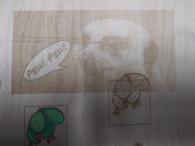
Here’s video of it running and PPI raster working (though I don’t have that version released just yet, soon though).

1 Like

I’m one of those still thinking about a laser cutter while finishing other projects, but I’ve been enjoying reading your MeerK40t (love the subtle use of the hex value of @!) source. I agree it’s pretty easy to navigate!

I’ve written rather a lot of python, so I had some fun reading it. I never read Whisperer code so not making any comparisons, but I agree that it looks modular and hackable. Thank you!

I had a thought about get_code_string_from_code() — isn’t an unknown code potentially fatal? Is there a reason you didn’t raise an exception there?

Also, my usual pattern for that would be declarative rather than procedural. Without raising an error, something like:

def get_code_string_from_code(code):
    return {
        STATUS_OK: "OK",
        STATUS_BUSY: "Busy",
        STATUS_PACKET_REJECTED: "Rejected",
        STATUS_FINISH: "Finish",
        STATUS_POWER: "Low Power",
        STATUS_BAD_STATE: "Bad State",
    }.get(code, "Unknown: " + str(code))

Typically the map would actually be outside the function rather than in it:

status_code_map = {
    STATUS_OK: "OK",
    STATUS_BUSY: "Busy",
    STATUS_PACKET_REJECTED: "Rejected",
    STATUS_FINISH: "Finish",
    STATUS_POWER: "Low Power",
    STATUS_BAD_STATE: "Bad State",
}
def get_code_string_from_code(code):
    return status_code_map.get(code, "Unknown: " + str(code))

Or, raising an exception:

def get_code_string_from_code(code):
    try:
        return status_code_map[code]
    except IndexError:
        raise UnknownStatusCodeError(code)

where, of course, UnknownStatusCodeError is an error class.

I’ve found that pattern of declarative maps easy to read and modify and used it many times so I thought I’d pass it along in case you like it. No obligation to agree that it’s better implied. :slight_smile:

I didn’t really want to waste memory on that and looking up data in a map seems like it’s non-trivial since it has to hash that and do some other stuff. And it’s going to be calling that function a lot and basically every time it calls it, it will equal OK or if it doesn’t it’ll equal BUSY. So the elif block should get the correct answer in 1 maybe 2 int compares. I’d typically opt for a case statement but without that I’ll go with an if, elif block. I might just think dict lookups take longer than they do. But, I tried them to speed up code at points and it always lost to the elif block.

There can be a couple other error codes that I don’t know about. That maybe I’ve never seen before. I found BAD_STATE by sending what basically amounted to gibberish and I’m still not sure what it means. But, that’s mostly for string description of the state to help people out in the Controller Window.

1 Like

That makes sense! I’ll go back to lurking for now. :wink:

Thanks for checking up on the code. I’m planning on providing some better documentation and some more robust testing. And maybe spinning the path.py file off into its own project. Since it has some major improvements over the original regbro svg.path project. But, making it hackable and understandable so reasonable programmers could contribute is a big goal.

Also, my use of hex isn’t entirely intended to be subtle. I spent a large chunk of time reading a lot of different proprietary embroidery filetypes. We’re talking months with my noise in a hex editor. So I tend to use hex for data in those cases where hex is more easily understood like when I’m dealing with numbers that’ll be written as a byte.

2 Likes

I wondered whether you had considered meerk@ or meerk40 (without the trailing t) as names.

I also know the experience of living in hex dumps. :joy:

For short MeerK is fine, I tried to come up with better names. I figured the 4 can be made in a logo to look like the A and then it gets Ka but I think Kaon was the only word that could use the 40 into KAO. But, meh. I didn’t give the name too much consideration. Or many of the design elements. It has a sort of angry fruit salad interface and a meerkat shooting lasers out of its eyes for an icon.

My idea there was to get some stuff that works then get maybe some designy people on board who could help. I’d be shocked if there weren’t a bunch who would use the product. So the idea was to get a working product, then ask for help with those other elements too. And they aren’t my forte so I didn’t give them that much time or energy.

1 Like

I also considered it without the 0. So it could be meerkat and meerk(fourty, 4t) which looks like 4t so k4t. But somebody had it already on github.

Thanks for the explanation.
I haven’t done the math on this yet but I wonder about the K40’s controller-LPS-Laser system having a high enough response for this to work well.
The PPI controllers that I have seen have been implemented in hardware.

The M2Nano board is tiny. Like it’s an 8 bit chip with some 16 bit registers. It doesn’t do any processing on the chip. It’s basically following ascii like machine code commands. That basically mean weird shit like add 13 mils of magnitude to the right/left buffer. Then when it sees the next directional command it’ll cause it to execute that. The speedcodes are literally two ascii numbers between 0 and 256 stuck together and they control the number of clock ticks until it sends a pulse to the stepper motor. It’s actually pretty neat but it relies entirely on the software doing the processing. It literally stores like 40 bytes of data in the buffer and tells when it’s okay to hand it the next packet.

I had to map out most of the scheme to do the work.

The link should be to the wiki documentation.

1 Like

It would be entirely possible to build a routine to run a fake gcode reader thing that uses the code here to more or less convert that over to lhymicro-gl code and feed it to the usb. So hook a raspberry pi zero to the board inside and then presto claim that that’s a GRBL. It will still have problems like the lack of acceleration up to speed will cause the machine to jerk beyond about 30mm/s in non-raster mode.

I was thinking of doing some of this stuff for my K40Nano project ( https://github.com/K40Nano/K40Nano ) . But, as the LightBurn folks pointed out they couldn’t use it since Scorch used a GPL3 license and just radically changing everything doesn’t make it not derived from that. And it’s not even a version that permits library inclusion for that license. So I wrote a java version from scratch. Added said java version to Visicut. Then wrote a python version from scratch, based in part on the Java MIT licensed version. So I ended up basically abandoning that project (K40Nano since it could only be GPL3). Though now with the MIT licensed version and more well rounded code here it could be revisited.

It shouldn’t be too hard to break the back end writer and controller code away from the front end GUI etc. In fact, it should be coded up to make that entirely reasonable. That way I could switch out the backend for like Ruida or something.

1 Like

As for the response time it’s fine, what matters though at some extreme ends is the time per command vs. time to send each command. At 100ms/s and typically 1/2 distance pixels the machine actually finishes all the code in its buffer before it can get more, which makes it lag out and restart in a stop sort of thing. If it’s a bit slower, or has commands that take longer to execute it’s fine. In raster mode we’re talking: DBaUBbDBa means go right 1 then laser up, go right 2 laser down, go right 1. So each 4 bytes to write 1 bit. Though when they are longer you get things like DBzzzz which means laser_on, go right 1024 mils. Which takes a much longer time than it took to send.

But, even when it caps out, which takes a bit, it just goes back to where it bottomed out and starts again without any error.

1 Like

By response I am thinking of the thread through the controller and the laser power supply and the laser itself.
What would the smallest pulse be at the fastest surface speed?

The lasers pretty close to instant given it’s wires at mostly the speed of light and light at the speed of light. The slow bit is the steppers which have a resolution of 1 mil which is also the smallest pulse of light. You can safely get to speeds of about 35mm/s vector but can go up to 200 mm/s for raster.

However, regardless the speed you’re going at the buffer can be taxed and it’ll slow you down if the time it takes to process the entire buffer is less than the time it takes to add new things to the buffer. The program will have a full buffer in a constant send loop but the machine can’t take it fast enough.

But for minimum amount to hit it with a laser, you’re looking at about 1/7000th of a second over 1/1000th of an inch. Though the laser itself will be a bit fatter than depending a bit on focus.

1 Like

Actually the laser subsystem does not respond (switch) at the speed of light. There are multiple factors at play, the LPS response but more importantly the ionization characteristics of the laser when presented with short on off pulses.

Unfortunately we do not really know the lasers response and measuring it has been illusive because reasonably priced devices that can see this spectrum are slow and to sensitive to put in the beam.

One of the benefits of PPI is that it should speed up the lasers response due to pre-ionization effects, how much … no idea.

The only published information I have found suggests a 100us response time but doing the math suggests that we would not be getting the good results we are seeing in the images.

Since @Tatarize has demonstrated results, it sounds possible and the question is about quality? I think what matters is:

  • whether total activation time is enough shorter than 143ns to result in no perceptible image change
  • whether there is a difference between activation response and deactivation response times that results in a non-linear power per area

Am I missing something here?

I’d think that if there are non-linear differences between on-response and off-response, applying a gamma curve to the image data before the PPI calculation would be a way to handle any such, and just engraving a series of 10% 20% 30% … 90% 100% areas and comparing them against each other through a 10% gray filter would be a good way to test whether there a gamma curve would be helpful to improve fidelity.

1 Like