Hm. That’s actually kinda genius. I mean I’ve done some color matching stuff and the only thing that really worked was to drop the physical thing on a flatbed scanner and scanning it with the good solid white light of the device. It wouldn’t actually be hard to raster a gradient like that as a particular test on a material. Then we could measure the effects of the medium, power-control setting, speed of the device and power modulation. I’m not sure how much you’d be able to dial that in, but you’d be able to basically bring any error down to an extremely minimal amount.
Might be material-specific curve because there might be a low constant loss on the “front end” as the material heats up that is different for different materials? Could run the test on both paper and plastic to look for meaningful differences…
I think photo supply houses should have calibrated gray film.
Oh, yeah, I’d want the test redone for each element. So run a raster test whereby you raster the ten half inch squares or so. Then you put that thing on a flatbed scanner. Scan it. And compare the 0, 10,…,90, 100 splotches. Typically by grabbing a large enough number of pixels to be statistically significant and averaging them together. And we’re not necessarily talking greys here. The difference on wood could be between wood colored and charcoal colored which aren’t exactly on a shade of grey spectrum wise.
I did the principle work for PhotoEmbroidery which took a lot of color matching ability and effort to get absolute best results. ( https://www.photoembroidery.com/ ) but, an with an analysis like that I could parlay my expertise into lasering things as close to the right colors as could be done.
I mean picture if you would a metal sheet that I dip in black paint, let dry, then dip in blue paint and let dry then dip in red paint and finally green paint. There’s a real chance differential lasering could isolate a paint color and you could end up doing colored lasered art. In what would be seemingly hard but entirely doable. And weirdly exactly in my wheelhouse.
1 Like
No where in this thread have I said nor am I challenging that this works!
We know that PPI can produce a better image. One theory is that the tube is held above its pre-ionization level and therefore has an improved response. I am interested in how and if PPI improves the lasers response.
I seriously doubt that this laser technology (its light) will respond to a 143 ns change. These tubes were originally designed to be used in CW applications. I have measured the rise time of current in these tubes to substantially exceed that scale. That is not to say that the light follow the cathode current… I do not know.
I am also not particularly referring to non-linearities between on vs off response (although there may be) but simply the ability of the laser to come to full optical power and to fully extinguish at the rate the PPI expects.
It obvious that if the rate that this system pulses the laser exceeds its response the effective dot at the surface will be somewhere between non-existent to smaller than expected. This will have a significant effect on image quality and any pre-work on the image might be wasted.
And of course what actually happens at the surface is highly dependent on dot size and material characteristics because the power profile in the beam is gausian and the materials physical characteristics vary by material and among the same material.
1 Like

A test that can show the total systems response can be designed as follows
Alternating vertical and then horizontal bars (made up of pixels) imaged left to right on the page varying the dot on/off pattern;
{
1 pixel on - one off
1 pixel on - two off
1 pixel on -three off
}
{
2 pixel on - one-off
2 pixel on - two off
2 pixel on -three off
}
…Repeat as necessary
With a loop you can measure the marks and spaces and tell how the system responds. If they match the source dimansions [in mark and space} then you are good if not any imageing you do will be degraded from your expectation.

I’m not sure I follow, or that that is a solidly good test. Isn’t the question whether the laser fires again faster than if it’s primed or not? Am I really supposed to measure a burnt dot/line about a 1000th of an inch wide? The pattern your talking about looks like partially burnt medium. The dots themselves tend to be bigger than than the distance to fire them.
Wouldn’t it prove the point more effectively to raster a vertical line with both initial lines and without them. So we have a central line at 50. And half the time we fire a laser up to the 50. Then the dot before 50 we turn the laser off then back on at 50. And the other half we just lead up to the point cold?
Then test whether that line is at altered in any manner by the prefiring?
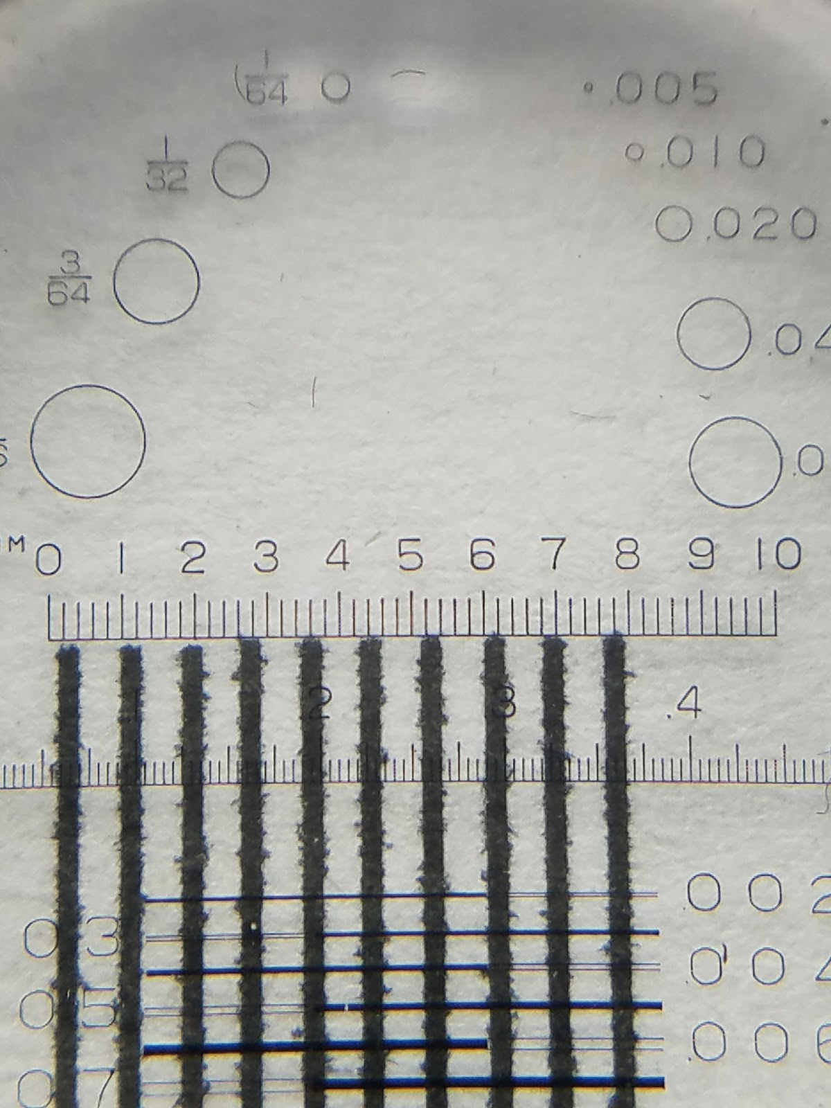
Though there we’re talking about a image that is a 1/10th of an inch. I guess I really would need a loupe (I assume you mean the homophone version there rather than coding this test in a loop).
I was not trying to prove the effect of PPI on laser response time with that test.
The test I suggested was just see if with and without PPI you had enough response to resolve a dot and if not at what point can you resolve the lines and spaces. This is a pretty standard test for marking system response.
@ 300 dpi you are looking at .003" lines and spaces and yes you can measure in that range with a good loope. The pictures in the last post are from a loope measuring output on a laser printer (don’t remember the resolution).
Your method for measuring the effect of pre-firing sounds like a good idea!
Ah, so just raster that image next time I’m at the laser and it’ll test the response time. If it’s slow it’ll make that stuff wonky. Okay, now I get what it’s supposed to do. Next time I wheel my computer into the dining room I’ll do that. (my process is a bit weird)
2 Likes
Curious what you found here, if you found anything?
Just caught up on reading this topic, so I’m late to the party.
I’m not much use to the development other than as a cheerleader, but I may be able to contribute one bit in terms of laser firing speed. I think that the limitation on the time to switch the beam on will be more determined inside the power supply than in the tube’s laser dynamics. If I read the schematics right, the stock K40 power supply turns on the tube voltage, runs it up to the ionization level, then when the tube ionizes and goes negative resistance, the power supply control loop goes into current limit to control beam power.
Those take time. Parasitic capacitance will likely make the pumping-up part of the pulse start be multiple cycles of the power supply clock to get enough energy in the wiring and tube capacitance to get the tube to ionize. The physics of gas ionization, population inversion and start of stimulated emission is likely to be much faster once you get up to ionization.
I’m unsure of what would happen when the power supply is told to turn the beam off. That’s likely to be faster than the power supply ramping the load voltage/current up, I think. But I don’t know enough about lasers to gauge how fast the stored energy dumps from the tube.
1 Like
When I ran this test on the M2 it had no issue at all. It just rendered the image perfectly fine and I could find no defect. Though I didn’t check with a loope and would likely have to. It has enough time to render a single dot.The chip is basically doing nothing except timing. Though it seems like there’s a couple other methods to do PPI if we’re just dealing with raw power amount and not doing anything weird.
2 Likes
I am a K40 laser user that has just found Meerk40t. As such the existing tutorials I have found are not simplified enough for a total newbie such as my self. Can someone please do an extremely basic step by step video to cut both a raster and vector shape? The PPI feature is of special interest to me. Thanks!
I had run through a workflow video but I checked and it’s really old like circa 0.3.0. There is a need for really basic instructions.
Make a normal svg file like you would for whisperer or some other program, drag and drop that into the scene. And hit the button that looks like a laser beam. Third ircon there. It’ll show you the job as it is arranged current and the operations it’s intending to do on that job. Hit execute commands. Then you’ll get “Start Job” because there’s nothing about the data that needs any tweaking. Hit that and it should start up the laser and start doing the job.
Lemme see if I can’t cook up a quick video.
Cooked up a video. Posted in its own thread. If you have any questions go ahead and ask there. I can work up some more basic instructions if they are needed. PPI you turn on and it draws lines with a more flickery laser. Works pretty nicely.
2 Likes
Awesome! Many thanks
Just adding some links that @Tatarize kindly posted elsewhere (going to have to use two posts because I only just registered):
Pulsing gives you more power and might even improve the lifespan of your laser tube: Getting More Power and Cutting Accuracy Out of Your Home Built Laser System at Buildlog.Net Blog
2 Likes
Pulsing can actually improve the quality of your raster engraving: Better Lasing With Pulses | Hackaday and DPI vs. PPI For the Laser | Engravers Network
David is indeed an absolute star!!
4 Likes