A strange observation. In my new laser, I call the big laser, the plasma beam that I see formed inside of the tube randomly changes orientation as it blasts out the end of the tube.
I fired up the k40 just now cause I have orders to fill and I decided to watch the laser tube. I attached a video that shows fairly consistent beam formation, very different from the big laser.
You might be testing with the same file but the controller firmware are very different and therefore what the laser is doing is going to be different. But you might have found that the firmware on the big laser is what’s causing the problem. A common firmware might be enlightening.
Let me put it another way, since you are using buffered type firmware and they are not the same, comparing what one firmware is doing at the laser to another firmware isn’t going to tell you much when you see variations.
But if that is indeed true, ie it was doing the SAME banding marking when running the same GRBL firmware then it’s the hardware or maybe the LPS. There have been some odd things happening with some LPSs in certain power ranges( usually low teens ).
after finding it I was reminded it was spotting throughout the engraving, not the banding you are seeing. Laser glitching around text
Frankly, I’m quite surprised you are seeing the same results at fast(200+ mm/s) and at slow(~50mm/s) speeds. Seeing the same period/spacing of the bands at different speeds, AND when you had the belt inverted just doesn’t sound right.
The spacing of the bands does change with different speeds. You can see that in the image I posted above (quoted below), apologies if I was not clear on that. Now what does not seem to change anything is inverting the belt. I did at one point have the GRBL controller connected to the big laser, it was displaying the same symptoms as the FluidNC controller. I swapped them because the guys developing the FluidNC software had a devastating bug with the Espresiff SDK and I was suspicious.
When I look at the picture below, all I see is a reflection of the GT2 belt pattern. It is damn near identical…
Somehow I must have missed the important fact that the pattern does change when you change speed. When I mentioned running at different speeds I thought you just said it still does the banding and nothing more.
Did you measure the spacing of the bands at different speeds to try and determine a correlation between speed and banding period? And I’m sure you know that as you change speed you also have to change power so that you’re getting the same amount of power dumped into each pixel.
It would also be helpful to provide the link to the post with the image instead of creating a low resolution image of a previous post.
I did not provide explanation. It’s not your fault, its mine. I did say “it still does the banding”. It does seem like the banding changes with speed, besides the images I have provided, I have no empirical evidence that shows the actual speed associated with the images I have posted. I will make a few burns tonight and associate them with speed and power settings. I will then make another post so I can provide more concrete evidence of what is happening and at what speeds and powers.
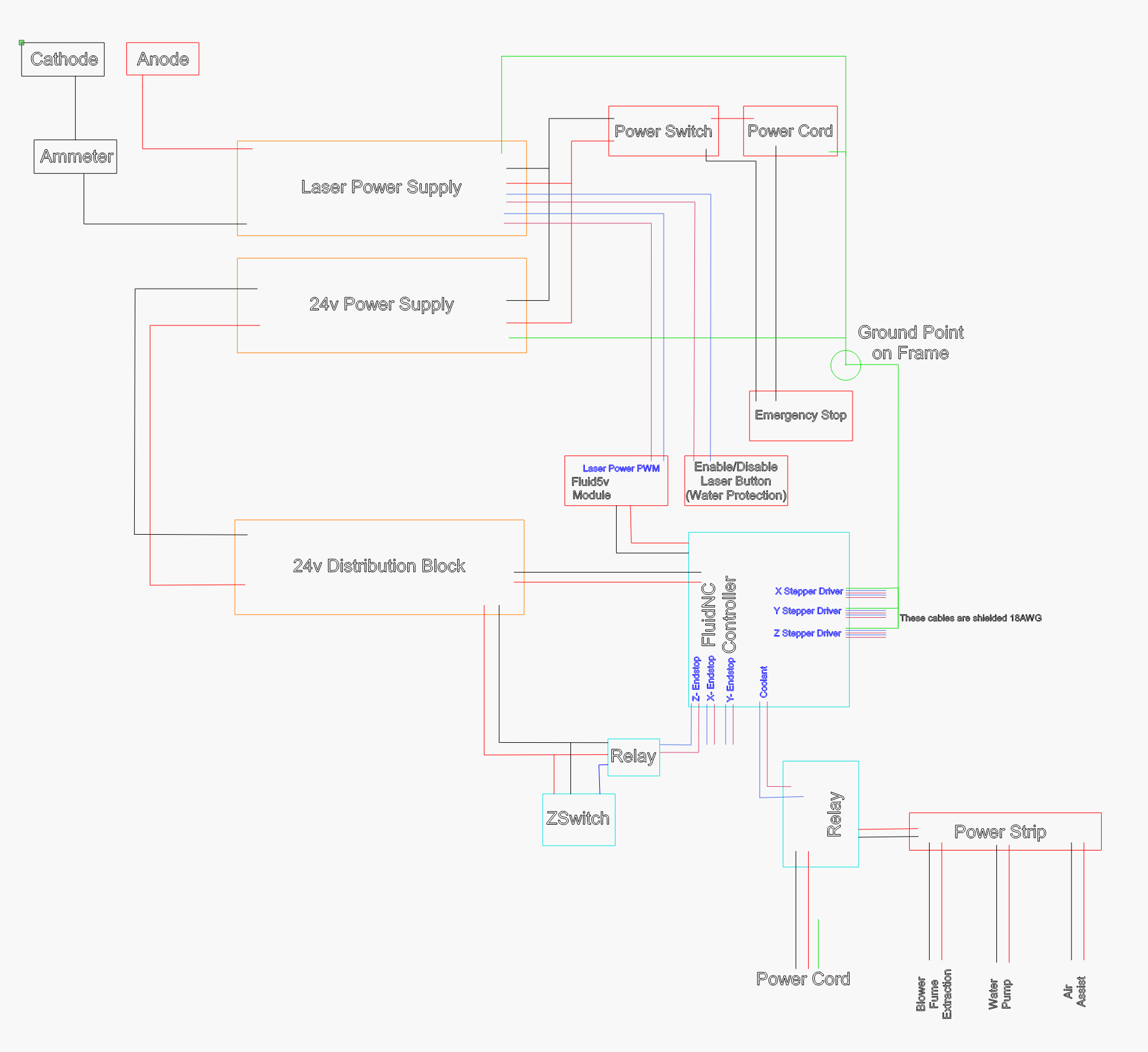
Varying with speed makes me wonder about how you are managing laser power. I don’t think you have shared a schematic with us?
Are you using an analog pot to set the max power, so that you can use the full range of digital PWM? If you aren’t, then you are using only a small portion of the 8 bits of PWM duty cycle, and I think you could end up with aliasing like this. This would be a difference from the K40 where you would be using a larger proportion of the digital range, and thus see less of an aliasing effect. I’m just listing one thing that could be related here, could be something else.
In any case, it’s worth listing all the components you used in the big laser with a schematic of how they are connected.
Judging by these comments, and my own experience, I would check the idler wheels riding the aluminum extrusion for nicks or out-of-round. I built a custom laser machine myself and had the same problems. Turned out it was the delrin wheels. Some were out-of-round, which would cause an oscillating pattern length equal to the circumference of the wheels. Also, when you load the gantries on to the extrusions, the sharp edges of the aluminum can pit the face of the wheels causing a repetitive disturbance in the motion.
So then maybe you put an analog meter on the laser and adjusted a POT inside the LPS to set your maximum power output?
Normally( DIY, K40, everything but Ruida ) uses a voltage set on the LPS-IN input(usually using a pot across 5V and the wiper going to LPS-IN) which sets the avg max power output and then you set your firmware so 100% PWM equates to this “max power”.
@jkwilborn on the LightBurn forum dug into this and found that the LPS still sends 100% power in a pulsed fashion(much higher freq ) even when the LPS-IN is set lower. So he has opened his LPS and adjusted the onboard POT(dangerous if you don’t know what HV is and how it can kill you) to limit the LPS from outputting more than the tube is rated for.
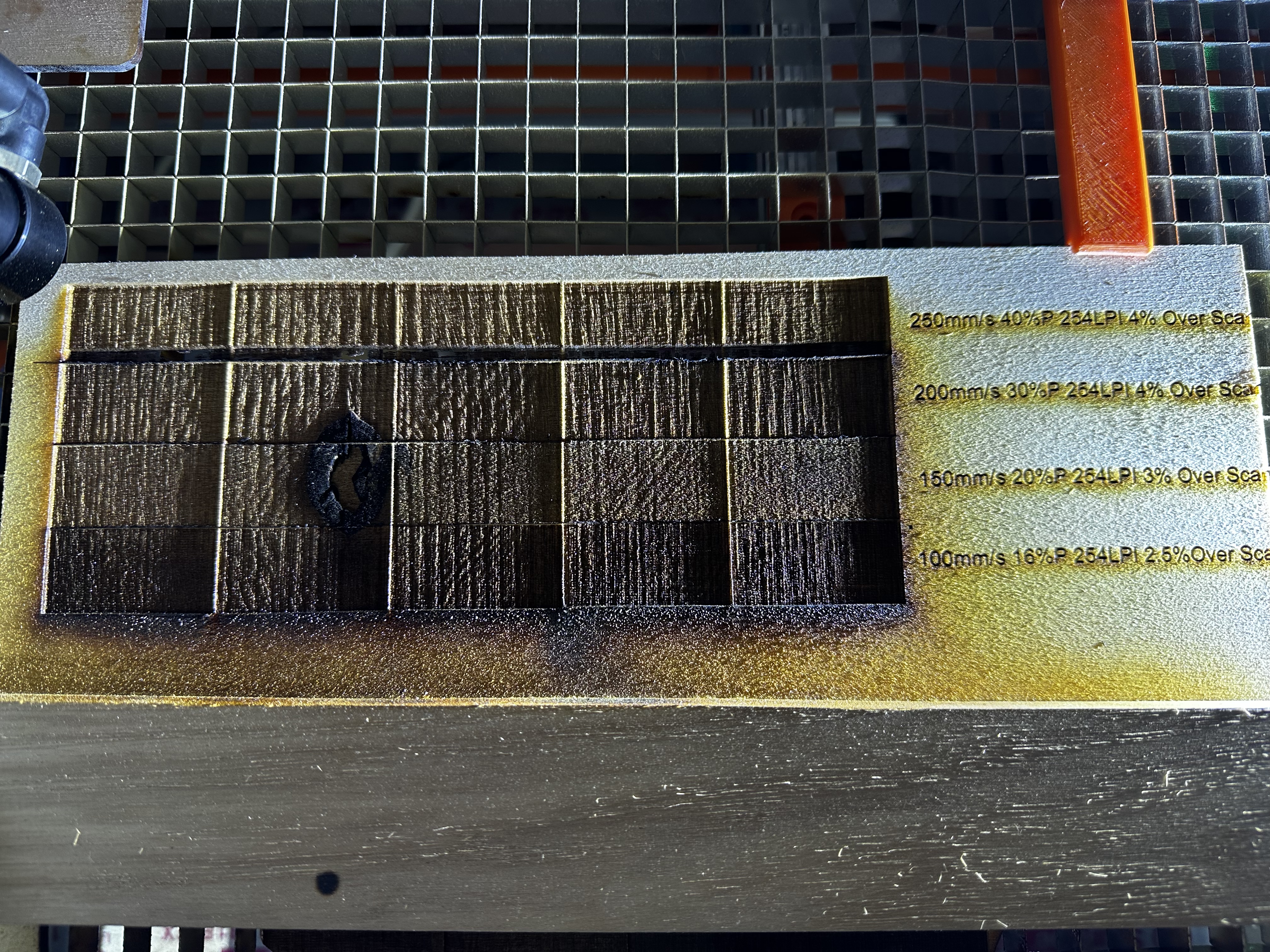
Well, I was wrong. Apparently it’s exactly the same at every speed. I don’t know how the image with pine in it had the lines so close together. This is essentially what I’m battling, a seemingly completely inconsistent result. Some days I swear I come out to the garage and it works for a few burns, and then the next day, or ten minutes later, it’s not working.
In this image, each row has 1 speed and power. I have it this way because as you can see the pattern appears differently across each 40mm x 20mm square. Each square was engraved individually.
I don’t know that the problem is electrical, but I’ll explain why I asked…
To get the same effective power from your 90W tube as you do from the probably ~30W tube in your K40, the max duty cycle for the 90W tube will be about 1/3 as long. This means that if you have the same PWM resolution on both lasers, you have fewer discrete values for PWM on the more powerful laser.
By contrast, if you use a pot to set the maximum power, and PWM for power relative to that maximum, you can use all the resolution of however many bits of PWM are available and get finer gradations of output.
I see that your speed map goes only to 50% power; if you used a potentiometer to set the max, you could make your power settings relative to your max setting on the potentiometer. (I also don’t know whether stopping at 50% in your speed map actually limits you to 50% power.)
Have you tried changing the pwm_hz Laser config setting to see whether it has any impact on the pattern? Try 50000 and see if it looks any different.
Edit: Oh, that was written before I saw that you were seeing the same thing at every speed.
To me, that points in the direction of mechanical and not resonance. Bad bearings, bad belt, wrong pulley (an MXL pulley with a GT belt will do this because MXL pitch is 2.032mm and GT2 is 2mm pitch and their tooth profile is different — but very close and so sometimes confused. I know that what you ordered was GT2 so that seems unlikely, but wanted to mention it because we have seen results that looked something like this, so trying to be complete).
I’m wondering why you are running StealthChop on y vs. CoolStep on x?
I cleaned up the X-Axis wheels and inspected them. I didn’t see any physical damage to the wheels. As I glide the gantry back and forth, I don’t feel an odd acceleration or wobble that might be caused by an oblong wheel. Do you have a better way to check for roundness?
Here are some videos of the actual X-Axis after I cleaned up the wheels…
To answer your question, the configuration file was given to me by Bart Dring himself. I’ve had multiple issues with the file I was given. I should have reviewed it more thoroughly. Doing a walk of shame to my laser to see if this is the issue…
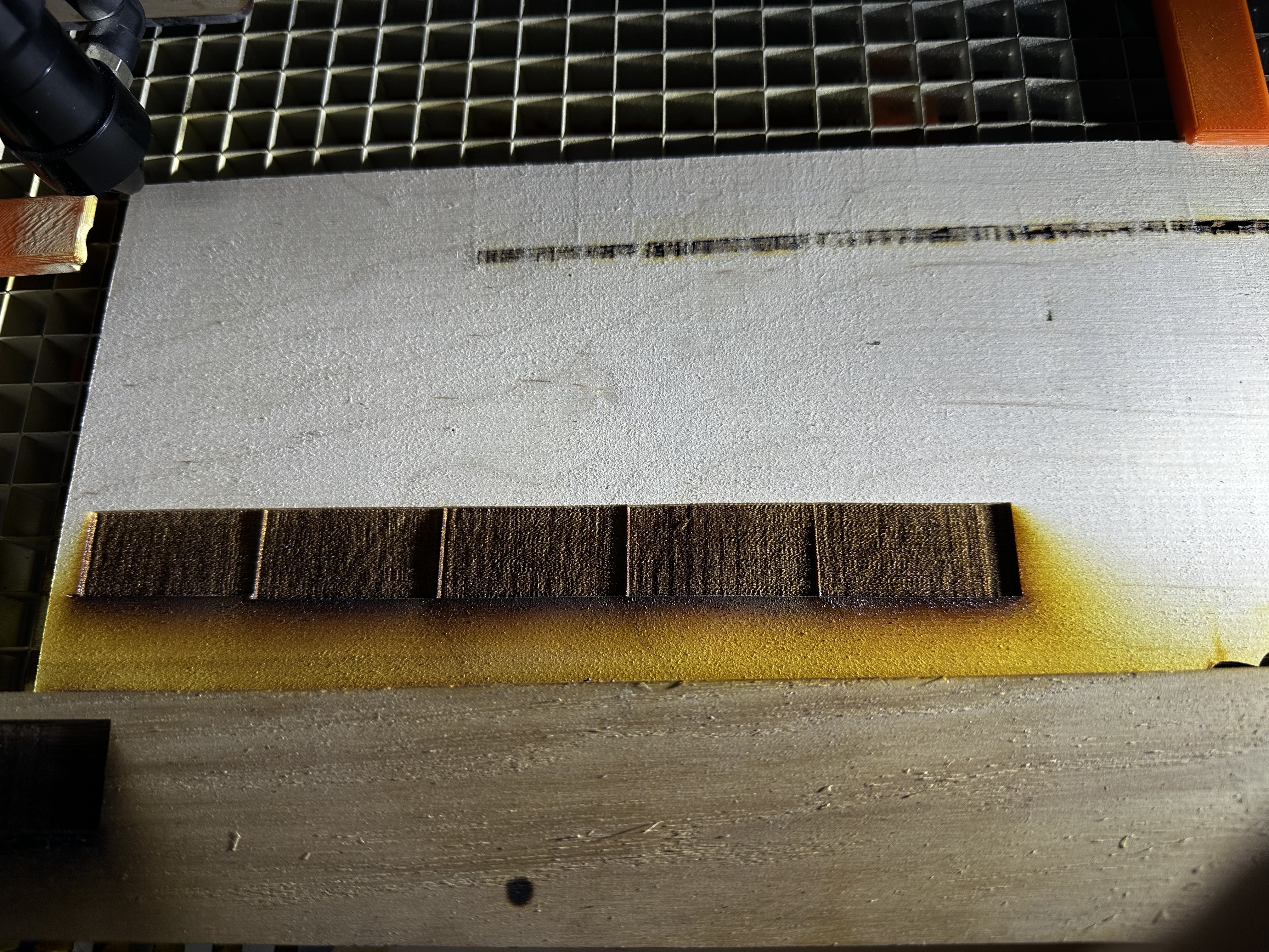
This is 250mm/s 40% power 4% over scan with stealthchop enabled on the x axis. The x axis sound completely and entirely different running in this mode.