“Curtains” in engravings

I didn’t miss your point, I understand that is a concern. I think that a substantial amount of thermal expansion would have to occur, like more than 1-2 mm on the 3D printed parts.

The thermal expansion coefficient of PLA is 68µm/m-°C
The gantry that the X-Axis rides on is roughly 3" or .0762 meters
I think an absolute MAXIMUM change of 30 degrees C from when I start to when I am done. (even though the patterns show up immediately). By the way, 30 degrees C is madness.

DL = (.000068)m per m Celsius *.0762m * 30C = .000155 meters ~ .15mm

This means that over 30 degrees C the expansion of the PLA is .15mm. The deformation of the v slot wheels alone can overcome this expansion. This also isn’t taking into account the thermal expansion of those wheels. If that was taken into account, there would probably be a net change of ZERO.

Please check my math, I am not a material scientist.

2 Likes

I’d think it much more likely that you have something like an intermittently bad bearing somewhere. Works when the bad spot isn’t lined up with running into adjacent ball bearings in the race, then stutters when it moves around to run into them. Or something equally hard to find… If you are moving enough air to void the smoke, I’d seriously doubt it’s a change in temperature.

1 Like

This is killing me. Replaced the v-slot wheels, still doing it.

I’m starting to turn into a tin hat wearing conspiracy theorist. I cut out an enclosure for the controller and wrapped it in foil tape just to see if maybe there was some electrical interference happening. No change.

Disconnected the relay control for the blower, water pump and air assist to make sure it wasn’t causing interference. No change.

Changed microstepping to 64. No change.

Smacked my head against the wall. No change.

Is there a problem with the laser tube itself no being enclosed in a metal box?

I started lightly banging the side of the laser while it was engraving and a different pattern resulted, but the underlying weird crap is still there:

Incredibly frustrating! I’ve been following this whole thing and racking my brain for helpful things to say.

I hate to come up with outlandish ideas, and I’m not sure I recommend this, but… If you put the K40 electronics and tube into the big laser, you’d know whether it’s a mechanical or electrical problem. (You would have to make something to adapt the tube size, of course.) This isn’t necessarily a better idea than smacking your head against the wall.

Higher-power tubes have a higher strike voltage. In general, lower-power tubes are better for finer engraving, and higher power better primarily for cutting. I kind of remember conversations here a few years ago about whether an LPS could/would maintain a voltage just below the strike voltage for high-power tubes to give better engraving results.

That’s ironic you mention putting the k40 tube into the big laser. I was just debating it. The major thing holding me back is the ability to fulfill orders…

I considered just buying another tube as well.

I think you can just use the existing LPS with a lower-wattage tube without problems. And there’s the point that the K40 tube won’t last forever, so a good-quality spare is more insurance for when that tube inevitably dies, right?

Sorry I was off on vacation.
This one hurts my head.
Here are my visceral thoughts as I have not read the whole thead thoroughly.

Just initial thoughts driven from experience … no facts.


Often these problems are elusive because during testing to many things are changing; speed, material response etc. This means that the underlying problem is masked by what the resulting image seems to be showing us. It’s good to simply keep trying stuff until the symptoms reveal the a-ha!


  1. Tempting but Not the LPS: typically these kinds of patterns are:
    a. material properties [changes in how the surface burns from sample to sample and test to test]
    b. mechanical tolerances [dynamic changes in motion. I have always been amazed how mechanical problems can seem to come and go]
    c. combinations of a&b
    I have never seen and can’t think of the mechanism for a LPS to all by itself create such a pattern especially at those low frequencies.

This will be a PIA but perhaps will provide new clues.
I would try to lock in on a very simple pattern to test with.
I like using horizontal and vertical line patterns that increase in frequency:
One dot on one dot off
Two dots on two dot off
Three dots on three dots off
etc…

Using it I would:

  • Image on a very stable material like acrylic.
  • Cross section and then polish the edge of the material so you can see the pattern clearly on the surface and also in penetration.
  • See if that pattern and its cross section provides clues.

Then run a series of tests to isolate x and y and various speeds and powers.


I will study the above thread and see if I can be helpful.

2 Likes

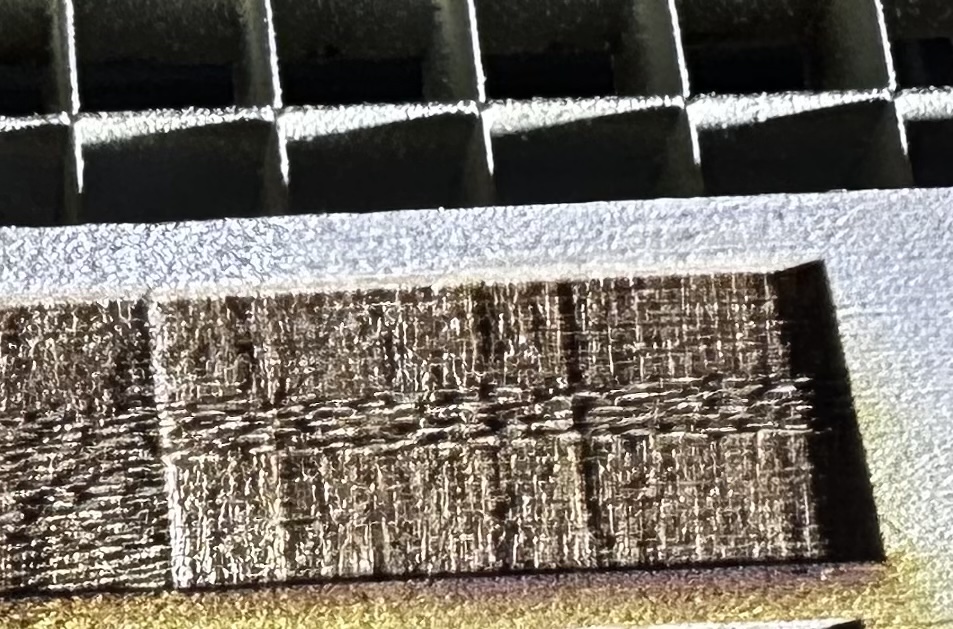
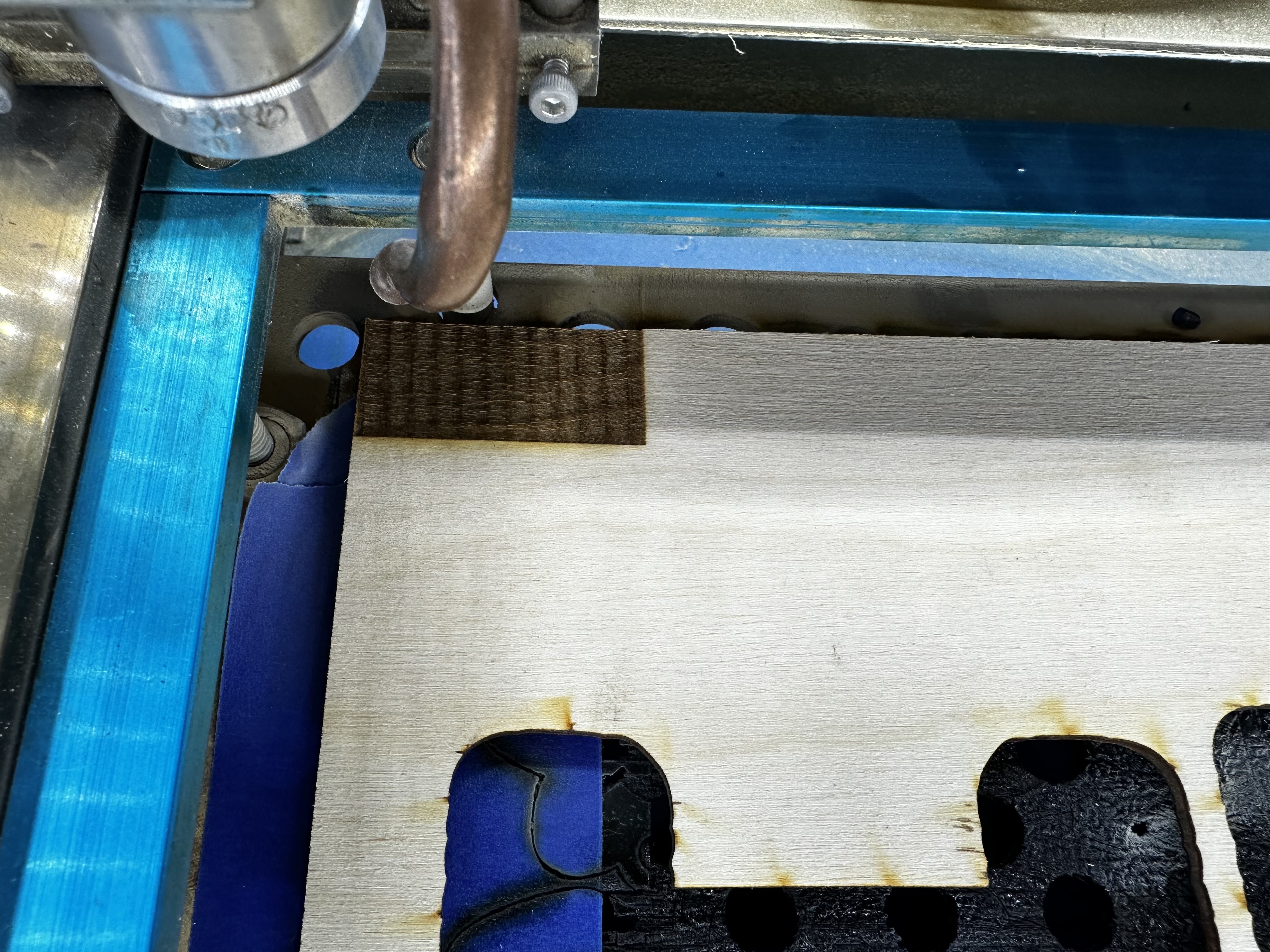
And the plot thickens… I moved back to my K40 for the first time in a little over a week, and the pattern is now showing up over here. This pattern hasn’t shown up on this machine, ever. I unplugged every appliance, computer, monitor, laptop, Arduino, Pi, 3D printer, anything that was on the same breaker as the K40, and the same thing was happening.

I made a pretty bold claim a while ago over on the lightburn forums, the issue I was having with offset cuts from engravings kind of just “went away”. Now, I am really starting to think Lightburn has some config file issues or something funky going on. Maybe it is my outdated version of Lightburn, I’m not sure, but I don’t really want to pay $30 to find out.

I’ve loaded Laser Web to see if I am having the same issues with its gcode. Some strange issues are occurring. The origin in Laser Web does not match with my origin on the K40, and the work offsets that I had setup for lightburn don’t really seem to apply to Laser Web. I have gone over the Initial configuration and machine settings on the Laser Web site a few times and nothing is really jumping out at me.

The error Laser Web is throwing is this:

ALARM: 2 - G-code motion target exceeds machine travel. Machine position safely retained. Alarm may be unlocked.

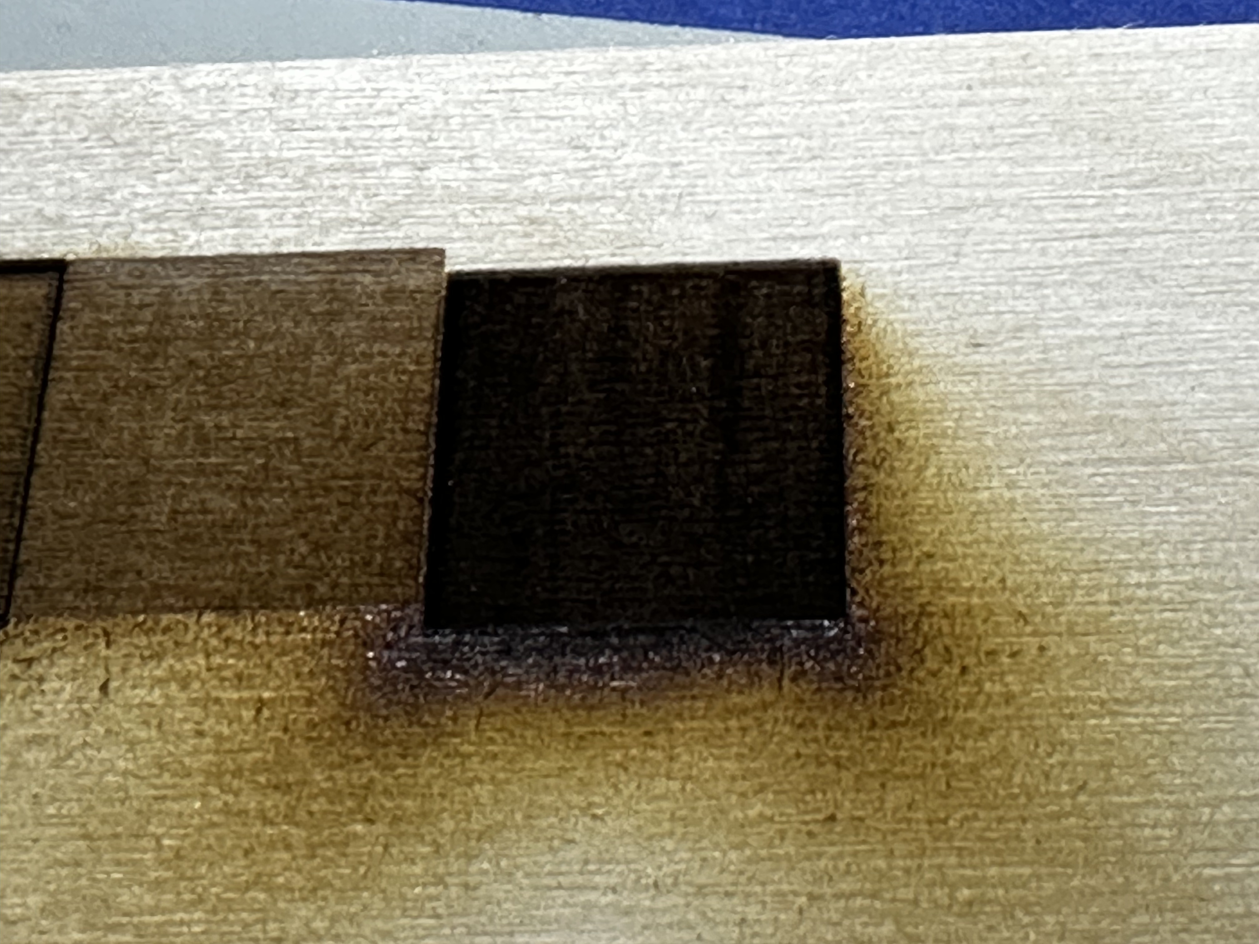
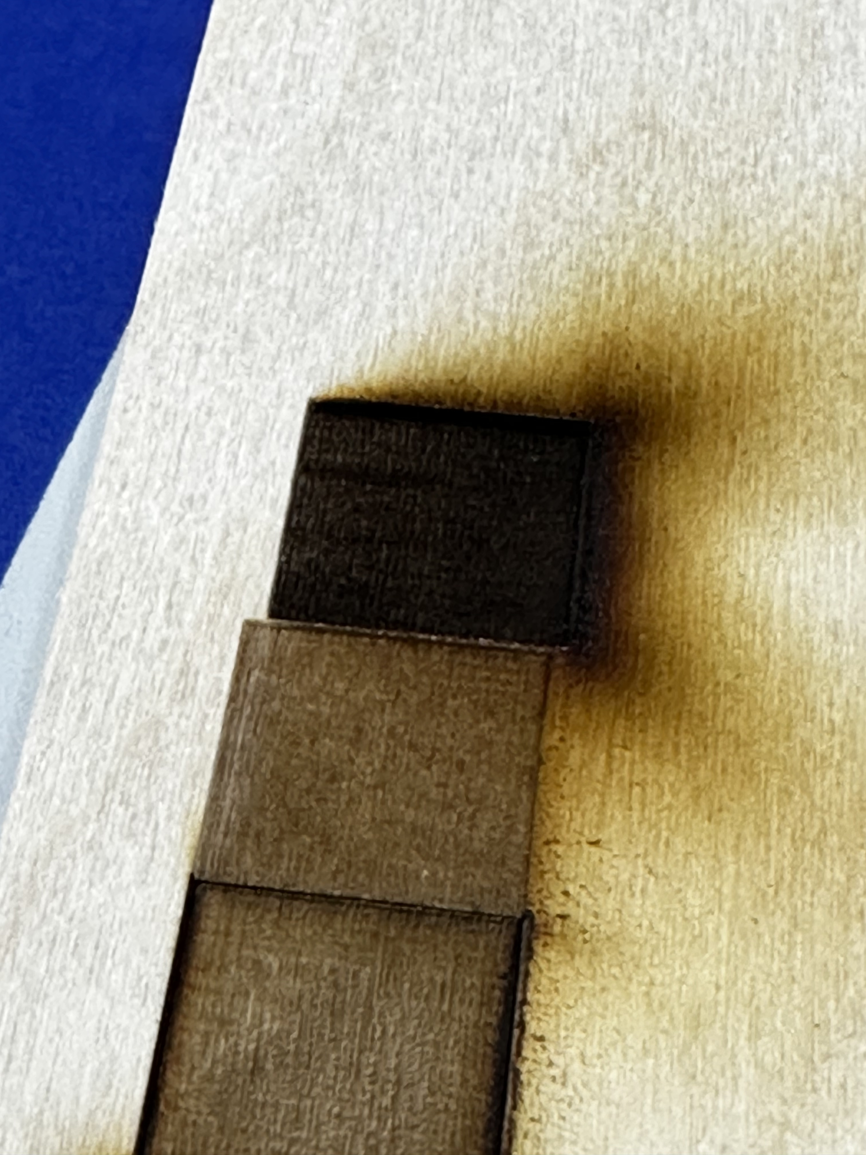
I understand that this means the gcode is telling the K40 to move into a space that will crash the gantry, but when I try to do the same thing in lightburn, of course everything works nicely. Inspecting the gcode, Laser Webs gcode is working in the negative space while lightburn is not. No matter the settings in Laser Web I cannot get this error to go away. I have attached the gcode from lightburn and the gcode from LAser Web.

I have included my Laser Web configuration for my K40, maybe something can be discerned from it…

{
  "__version": "4.0.999",
  "__selectedProfile": "K40",
  "__latestRelease": "2019-11-26T10:45:07Z",
  "showMachine": true,
  "machineWidth": 321,
  "machineHeight": 192,
  "machineBeamDiameter": 0.1,
  "machineBottomLeftX": 0,
  "machineBottomLeftY": -192,
  "machineFeedRange": {
    "XY": {"min": 100, "max": 6000},
    "Z": {"min": 1, "max": 1250},
    "A": {"min": 1, "max": 50000},
    "S": {"min": 1, "max": 1050}
  },
  "machineXYProbeOffset": 0,
  "machineZEnabled": true,
  "machineZMatThickness": 0,
  "machineZToolOffset": 0,
  "machineZStartHeight": "",
  "machineZProbeOffset": 0,
  "machineAEnabled": false,
  "machineBlowerEnabled": true,
  "machineBlowerGcodeOn": "M08",
  "machineBlowerGcodeOff": "M09",
  "pxPerInch": 72,
  "forcePxPerInch": false,
  "dpiBitmap": 72,
  "toolGridWidth": 321,
  "toolGridHeight": 192,
  "toolGridMinorSpacing": 10,
  "toolGridMajorSpacing": 50,
  "toolSafetyLockDisabled": false,
  "toolCncMode": false,
  "toolImagePosition": "TL",
  "toolUseNumpad": false,
  "toolDisplayCache": false,
  "toolUseGamepad": false,
  "toolCreateEmptyOps": false,
  "toolVideoDevice": null,
  "toolVideoPerspective": {
    "enabled": false,
    "before": [
      170.66666666666666,
      384,
      682.6666666666666,
      384,
      682.6666666666666,
      96,
      170.66666666666666,
      96
    ],
    "after": [
      170.66666666666666,
      384,
      682.6666666666666,
      384,
      682.6666666666666,
      96,
      170.66666666666666,
      96
    ]
  },
  "toolVideoLens": {"a": 1, "b": 1, "F": 1, "scale": 1},
  "toolVideoFov": {"x": 1, "y": 1},
  "toolVideoResolution": null,
  "toolVideoOMR": false,
  "toolVideoOMROffsetX": 0,
  "toolVideoOMROffsetY": 0,
  "toolVideoOMRMarkerSize": 20,
  "toolWebcamUrl": "",
  "toolFeedUnits": "mm/s",
  "toolTestSValue": 1,
  "toolTestDuration": 0,
  "gcodeStart": "G00 G17 G40 G21 G54\nG91\nM4",
  "gcodeEnd": "G0 X0Y0\nM2",
  "gcodeHoming": "$H",
  "gcodeGenerator": "default",
  "gcodeToolOn": "",
  "gcodeToolOff": "",
  "gcodeLaserIntensity": "S",
  "gcodeLaserIntensitySeparateLine": false,
  "gcodeSMinValue": 0,
  "gcodeSMaxValue": 1050,
  "gcodeCheckSizePower": 1,
  "gcodeToolTestPower": 10,
  "gcodeToolTestDuration": 200,
  "gcodeConcurrency": 2,
  "gcodeCurvePrecision": 0.1,
  "comServerVersion": "4.0.138",
  "comServerIP": "localhost:8000",
  "comServerConnect": false,
  "comInterfaces": ["USB", "ESP8266", "Telnet"],
  "comPorts": [
    {
      "comName": "COM4",
      "manufacturer": "Arduino Srl (www.arduino.org)",
      "serialNumber": "55431303937351908102",
      "pnpId": "USB\\VID_2A03&PID_0043\\55431303937351908102",
      "locationId": "Port_#0002.Hub_#0002",
      "vendorId": "2A03",
      "productId": "0043"
    }
  ],
  "comAccumulatedJobTime": 3463,
  "connectVia": "USB",
  "connectPort": "COM4",
  "connectBaud": "115200",
  "connectIP": "",
  "jogStepsize": 10,
  "jogFeedXY": 1000,
  "jogFeedZ": 100,
  "macros": {
    "*GotoXY0": {
      "label": "Goto XY zero",
      "gcode": "G0 X0Y0",
      "keybinding": "f1"
    },
    "*LaserOff": {"label": "LASER OFF", "gcode": "M5", "keybinding": "f2"}
  },
  "uiFcDrag": null,
  "machineOriginX": 0,
  "machineOriginY": 0,
  "toolUseVideo": false
}

Lightburn GCODE:

; LightBurn 0.9.14
; GRBL device profile, current position
; Bounds: X0 Y0 to X40 Y20
G00 G17 G40 G21 G54
G91
M4
; Cut @ 6 mm/sec, 35% power
M8
G0X0Y0
G0Z-2
G1Y20S367.5F360
G1X40
G1Y-20
G1X-40
G0Z2
M9
G1S0
M5
; return to starting pos
G0 X0Y0
M2

Laser Web GCDOE:

G21
G90


;
; Operation:    1
; Type:         Laser Cut
; Paths:        1
; Passes:       1
; Cut rate:     100 mm/s
;


; Pass 0

 M08; Enable Air assist

; Pass 0 Path 0
G0 X41.00 Y-21.00
; Pass Z Height 0mm (Offset: 0mm)
G0 Z0.00

G1 X1.00 Y-21.00 S367.50 F6000
G1 X1.00 Y-41.00
G1 X41.00 Y-41.00
G1 X41.00 Y-21.00
G1 X41.00 Y-21.00

 M09; Disable Air assist
M2
G0Z50
G0X0Y300
M911G4P500M912G4P100M911G4P100M912G4P50M911G4P100M912

@cprezzi or @easytarget — is there a laserweb setting for what quadrant it works in?

@mcdanlj
There is no such setting, it only depends where the work origin is set. But we always expect to have positive directions to the right / back.

@James_Harding
There is a difference between machine coordinates and work coordinates. Homing sets the machine origin (0/0). LaserWeb internally uses work coordinates (with positive directions to right/back), so the origin can be set where ever you want. You only need to make sure that the firmware reports work coordinates, not machine coordiantes (GRBL $10=0).

If LW reports that a move will go out of bounds, this is related to the work origin. Move to front left and click “set zero”. This will set the work origin to the actual location.

In GRBL you can configure the homing coordinates that are set at homing. For example: If you home to back left, then homing coordinats could be set to 0,192 (which sets the machine origin to front left).

1 Like

Progress report…
On the K40, it seems I was able to shake the issue by adjusting the $30 Max Spindle Speed. I’m not sure how or why this changed, or why I needed to change it but the image below is pretty telling.

I think that this might actually be the issue. I have ordered a set of pots for the big laser, I plan on doing the installation tonight, although I’m not 100% on how to tune the software, searching the google machine now for some guides.

Edit: Upon further review of the FluidNC wiki, I don’t think I need a potentiometer in the loop. The speed_map they provide should allow me to limit the max output of the laser, while giving full resolution of power at the same time: Spindle Speed Maps | Wiki.js

The speed map (which you are already using) doesn’t magically preserve resolution.

The output PWM values are still a linear series, and if you map to a different range you use only the values in that range.

I’m not saying you need a potentiometer, but the speed map won’t give you full resolution. I don’t know if it will matter, though! If it would I would have expected to have had a change (if not an improvement) from changing pwm_hz.

Well, if i set my speed map to:

0=0% 1000=50%

Then I will maintain the resolution, values 0-1000, and limit the power of the laser to not exceed the mA value that I have chosen (happens to be 50%).

Is this not what the potentiometer would effectively do?

Yes and no?

You are using only half the resolution that way. You are telling it to ignore one of the max 16 (I think) bits of resolution by limiting the output to 50%.

That’s probably not relevant in your case since changing pwm_hz showed no change.

But the potentiometer would give you all 16 bits of resolution and map them to the bottom 50% (or whatever you dialed it to). This gives you more possible shades of gray.

You might not care, and it might not matter for you! But depending on the hardware and desired output, the difference does matter for some cases for some people. It matters more when fewer bits of resolution are available.

Additionally, laser tubes wear out over time. You can use the potentiometer to set equivalent cutting power, so that the same cutting file acts the same even though the tube has aged, by adjusting the maximum power on the potentiometer. Folks wanting to keep a library of cutting files and adjust the laser cutter like this feature of the potentiometer. You will have students creating new files and adjusting power at that time, so it probably doesn’t apply to you.

So for you it’s probably effectively the same, but for others it won’t always be.

2 Likes

I just completed the setup as number 2. The way that I had power control setup before seems a bit whacky now, but I am still seeing the same results.

I don’t think 50,000hz is a good setting in this configuration, my mA meter is all over the place with seemingly no control. I tried at 2.5k, 5k, 10k, and 15k. 15k seemed to be the best, I get a nice dark burn.

My speed_map = 0=0% 1000=100%

As I said, the pattern is still here :frowning:

Oh, I doubt it is. My point was to choose something an order of magnitude different from where you were to see whether it changed the banding. It makes complete sense to test different values and choose what looks best!

The fact that nothing has changed the pitch of the pattern has made me say before that I believe that your underlying problem is mechanical not electrical, so all the electrical/software suggestions from me are my understanding (which may be flawed) of how to get best results after resolving the banding.

So many problems like this are really belt-related in the end. The same thing can be true with 3d printers…

2 Likes

and over-tightening the belts can be as much of a problem as too-loose belts…

3 Likes

Ruled out the x axis as the cause.


Complete redesign of the x axis with nice linear rails.


Working on fitting all new corner brackets that will make the frame more rigid. Either this will make it worse because it’s more rigid, or it will fix a weak link somewhere along the chain that has been making it resonate at just the wrong frequency.

3 Likes

I got roughly 28 new brackets installed, bigger and stronger. Squared up the frame better than it has ever been. 4 new T shaped brackets to stabilize the main gantry system that the X and Y axes ride on. Changed out 4 adjustable 3D printed feet with 20 rubber feet. I also redesigned the mount for mirror #2, it is substantially more stable and simple.

I forgot the third possibility, no change whatsoever. Engravings look exactly the same. Wasted a solid 16 hours tearing apart the entire machine to do these “improvements”. Serious blow to my motivation.

It has helped narrow it down a little bit though. Things I haven’t changed/could still improve upon:

  • Y-Axis
  • Laser Tube
  • Laser Power Supply

Things I have tried:

  • X-Axis redesign (4 iterations now)
  • Removing Z table
  • Adding potentiometer to properly limit current
  • Adjusted pwm frequency for laser power signal
  • Removed exhaust fan from bench (vibration source)
  • Removed water pump from bench (vibration source)
  • Inverted X-Axis belt to prevent GT2 belt grooves from being a source of vibrations
  • Increasing rigidity via brackets
  • Laser Lens secure
  • Laser nozzle secure
  • Clean and secure mirrors
  • Gutted the electronics, very simple setup now