After a few years of thinking and reading about building a DIY CNC mill I’m to the point where it’s time to start nailing down the details and then buying materials.
I have a $5k budget for a mill and basic tooling. I already have a Dell PC to drive it.
Here are my design constraints:
Three axis table mill with XYZ motion envelope of 300mm x 300mm x 150mm
Can easily slot mild steel and occasionally make light cuts in stainless without too much fuss
Can hit tolerances of +/- 0.05mm (~0.002")
Fits on top of my CR-10s5 enclosure/bench (~500mm x 500mm top surface)
Air, water, lube, control, and coolant systems can be tucked away behind the bench
Is fully enclosed to contain flying metal, liquids, fumes, and noise
Driven by a fully FOSS workflow like: FreeCAD → LinuxCNC
Open licensed hardware designs but I can live with closed control boards and motor drivers
Ideally flood coolant but I can live with good mist coolant
Split phase 220V because getting more to my shop would be an expensive PITA
I’d love an ATC but can live with a powered drawbar or similar
My budget is $5k but I can live with adding the “nice to haves” later as long as I have a working mill and basic tooling when the initial budget is spent
Easy peasy, right?
At work I have access to a CNC lathe (Haas TL1), a CNC mill (Haas VF2), surface grinder, welding rig and various other machine tools. In my shop I have sheet metal tools, printers, a 3018, and other light work tools.
Stay tuned for more exciting adventures in DIY CNC!
My leading idea for the frame is to weld steel with interior spaces into which I cast ~50kg of epoxy+granite. I think for this size and force that should provide enough rigidity and dampening.
Yes, the need to enclose it in a maximum of ~500mm in width and depth (due to bench size) pretty much means that if I want 300mm in X and Y then it’s a gantry.
I’m also thinking BT30 to enable ATC at some.poont. There are a couple of common water cooled 3KW spindle + VFD packages around $2k that might work.
Are you thinking of prismatic ways or linear guides? I’d think with your work tools you might be able to fab prismatic ways, and you’ve actually studied this, so you might be more able than tyro me to hold 2 thou across ~400mm. But I’ve also heard that making good gibs can actually be quite a pain.
I’ve occasionally thought of using my real mill to modify my mini-mill to take tapered gibs and make up some tapered gibs, but so far I’ve always regaine my sanity and taken up a different project instead.
I’m thinking linear rails for rev 1 as they’re easy and relatively inexpensive. If they turn out to be a source of too much slop then I’ll find or cut something better like prismatic ways. I suspect that there will be enough custom parts to keep me busy in the meantime.
I’m thinking about pitching the rails in to put them in alignment with upward forces during plunges. This will also more closely align them with forces along X and Y.
Yes, with a static table the rails will be higher than the work, though they’ll still need wipers and probably accordion covers to keep flying swarf at bay. I might whip up some sheet metal covers like those on the ways of movable tables in larger CNCs.
I have an alternative idea which could solve a number of the design goals.
The bench which encloses the CR-10s5 has an unused, full height pocket to the right of the enclosed section. When I built the bench I left it empty with the intention of eventually placing my air compressor toward the rear and a small cart with drawers toward the front.
So my alternative idea is to instead make the frame of the CNC the full size of the pocket with machine casters so that I can pull it in and out as needed. This would leave the top of the bench clear for working surface while using the existing structure as an enclosure for noise and fumes (though not chips and coolant). It could also increase rigidity and save a bit on one of the ballscrews + rails cost.
A major downside is the reduction of the length of the Y-axis. One of main reasons I want a larger CNC is to cut long metal leg parts for walking mechatronics which would still be possible with less Y motion. The future is a funny place for generalists, though, and this does collapse the possibility space. A common dilemma, I suppose.
If your goal is long parts, why not just do a standard bench mill CNC conversion? I’ve heard that while they don’t list them on their web site, if you call Precision Matthews they actually have some frames for CNC conversion available, or at least have had in the past, and their tables are a bit longer in X than a lot of sieg variants. In that case you could use TTS in an R8 instead of BT30 for an ATC system. Converting the PM-833TV to ball screws if you could just get the frame parts would not horrible from a price point. it’s a bit under $5K OOTB so given your specs I’d certainly be inclined to call them and ask.
X Axis Travel: 21-3/4” Max
Y Axis Travel: 11” Max
Z Axis Travel (Head): 17-1/2” Max
My initial response to this idea was “heck, no” but I quickly realized that I didn’t know why. It’s a good idea on many fronts!
So, I slept on it and spent time poking at my feelings. It seems that I have a mental image of how much and what type of DIY I want in this build and for some reason using a premade frame isn’t in that image.
That said, I am fully aware that I will regret this decision. Probably several times. But here we are.
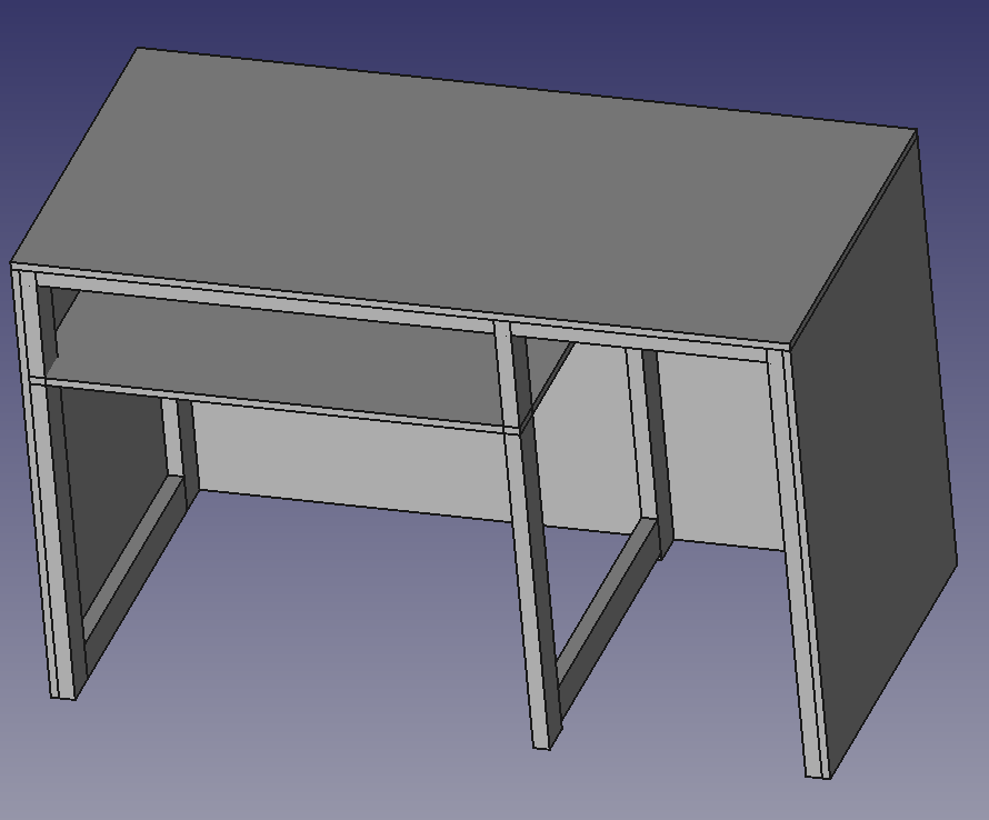
Ok, here’s a rough drawing of the bench. The pocket on the right is where I’m thinking of running the CNC mill. The lower left pocket is where the CR-10s5 sits.
The measured dimensions of the right pocket are:
height: 1160mm
width: 600mm
depth: 1140mm
The taller the gantry, the wider and thicker it has to be, obviously.
The more than 1M depth gives some room to have a very stiff gantry and still have all the travel you want.
With a gantry, you have to decide how to synchronize the screws on each side. The stiffer the gantry, the worse it will be to rack it. Maybe consider a single motor and timing belt between them? You don’t have to limit yourself to belt loop lengths that are commercially available; I posted a way to join a belt into a loop accurately that is very strong (when I tested it using my hydraulic press, it failed elsewhere, not at the joint).
Yes, I agree with you about using a single motor to drive the X screws. I was planning to find a common belt length but now I know about your custom length process. So, that’s handy.
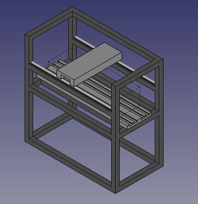
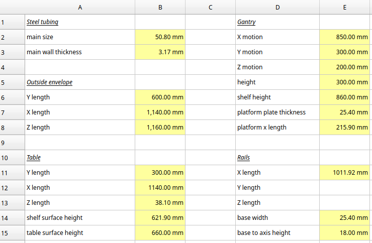
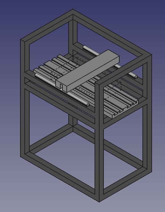
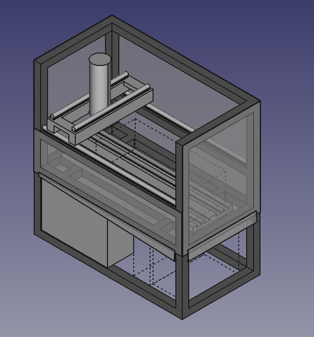
When I have a moment away from Alto production I want to hop into FreeCAD to block out the major components so that I can nail down part dimensions and then find their sources.
I know of a few sites like Steppers Online, eBay, and Alibaba but I’d love to hear about any recommendations you have.
Those weren’t special, I just found what I was looking for and placed orders that went fine.
Now that I’m back at a keyboard, here’s the belt loop splicing technique I came up with, which was illustrated with that 5mm HTD belt, where I made a nearly 5M long loop:
Your tolerances may be tricky. I’d use large ball screws; maybe 2005? C7 is widely available (random aliexpress shows it at $65 for 1M) and is specified ±50µm/300mm. I see listings for C5 that say that C7 was shipped instead, so it looks like you have to pay attention and make sure if you are going C5 or better ground screws instead of C7 or looser rolled screws that you actually get the higher precision you pay for, at least on aliexpress. But that’s just the screw tolerance. I assume you’ve worked through at least roughly how the tolerances would stack up and what you could accept at each interface to still hold two tenths?
Skipping a step on a stepper motor would be expensive at that scale. You might want a servo instead, or a closed-loop stepper. If I were building something in that price range I’d definitely be using a servo.
Looking forward to seeing initial design ideas once you have the time to do them.
Hats off to you for all the upfront planning. It’s great that you have a lot of experience to go by in making a plan. I would not presume to advise you on this since you seem to be coming at it with a lot of experience, but on the chance that you might learn something from the build I did a few years back I can talk about that.
First, I came to the world of machine tools and CNC knowing very little, so I did some experimentation with basic leadscrews and steppers light guide rails driven by a tinyg controller and an existing router for the spindle. It was an okay setup for learning, but not near stiff enough to do well with metal cutting, so I decided to do something that would be stiff enough to do a decent job on aluminum and light cuts in steel.
Version 2 of my setup meant 16 mm ball-screws and 20 mm square guide rails with some larger steppers and a air cooled 1.5 kW ER20 spindle. Still not nearly as ambitious as your plan, but ultimately, I got something working withabout 30" x 15" of x-y and stiff enough to do a good job on steel and aluminum with an accuracy of about .002". The spindle setup will not ever handle auto tool change, and my design isn’t enclosed, so I have to let the chips fly where they may. https://www.youtube.com/watch?v=zExZ78TMWIo
I posted a brief video if you want to take a look just for ideas. Ultimately, I was able to get a lot of stiffness by bolting the whole thing down to a bench that was already attached to the block wall in my basement and bolting the column to the block wall greatly increased the stiffness of the spindle assembly.
Hey, Walt. Thank you for sharing your build! I’ve used a fair number of machines but this will be my first custom build.
That’s pretty smart, using saw tables that you had on hand. My shop space is too small to keep much stock and I don’t keep even one working table saw!
I’m still thinking through options for the table. I’d like something like a Pierson work holding plate with precision bored and tapped holes so that I can quickly swap fixtures with high repeatability. I also need to make it with a low profile to leave space for the Z travel that I want so it’ll be a balancing act.
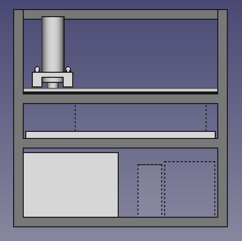
The control box sits toward the front on the lower left.
With the total footprint that I have for this and the cutting envelope that I want (dotted lined box above the table) I think that I can leave space on the left side of the table for some sort of ATC rack.
I’m considering Teknik’s NEMA 34 Clearpath Servos that have integrated drivers. This model is driven by the boring old “step and direction” signals so when I need replacements in the future I’m not stuck with one vendor.
I’m a bit annoyed that searches for “servo” on sites like eBay, alibaba, and Amazon turn up results that are almost entirely for closed loop steppers pretending to be servos.
A couple of these power supplies (also from Teknik) would fit into the cabinet and (I think) handle the three initial servos and a potential 4th axis servo in the future.
Those Mesa boards are mostly out of stock, right? I ordered a 7i96s control board and a 7i84 I/O card because they’re in stock and supported by LinuxCNC. I’m not so confident in the longevity of a company that has so little stock, though.
I’m still browsing spindles and VFDs. There seem to be a couple of spindle kits that are rebranded by everyone and their brother so search results are almost exclusively filled with the same kits.
I decided to name this design “The Chela Mill” and have started a Codeberg repository where I will share design files as soon as I neaten them up a bit.