One nice aspect of working on a machine design in public is that people with a variety of experience will offer advice and pointers to references. For example, in this Fediverse thread I’ve received links to helpful PDFs about linear motion guide configuration:
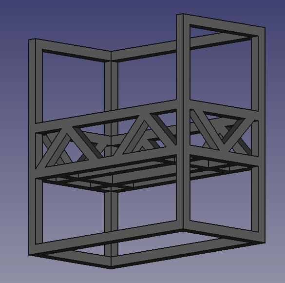
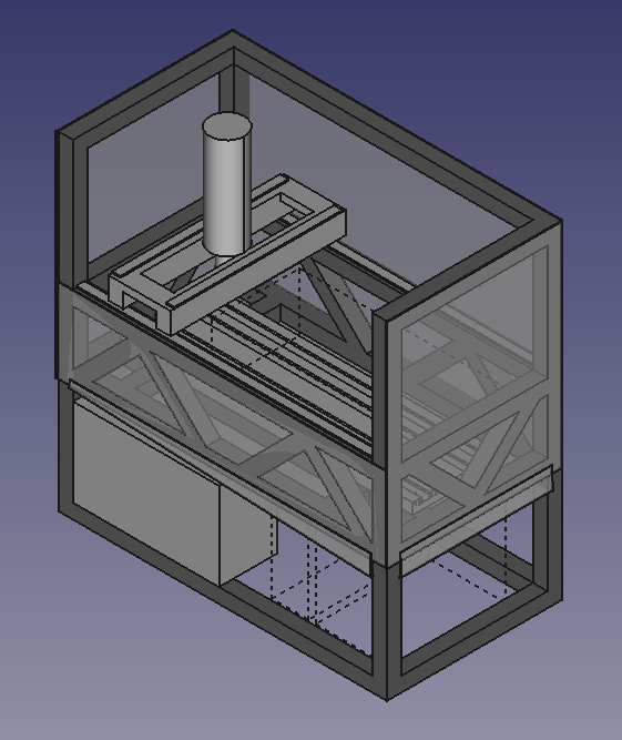
I’ve also received helpful advice about strengthening the section of the frame that handles most of the forces involved with cutting steel. I added space frame (ish) support and am planning to fill that section with epoxy granite.
One other piece of advice that I’ve received from multiple people is to use boring old open loop stepper motors (instead of the expensive Clearpath servos) and use LinuxCNC’s trick of closing the loop with glass scales. Their arguments for this are that it’s less expensive, I won’t drop steps unless I’m misusing the machine, I won’t be locked into a vendor, and directly measuring the position of the gantry and spindle is better than indirect measurement of the motor position.
To get some direct experience with LinuxCNC I’ve ordered a couple of boards from Mesa USA, as well as a motor and driver that was recommended by a machine tool builder in my neighborhood.
There are a lot of 48V PSU models around 10A which seem like a good balance of cost, power, and noise. I would prefer a DIN rail unit which seems to drive up the price.
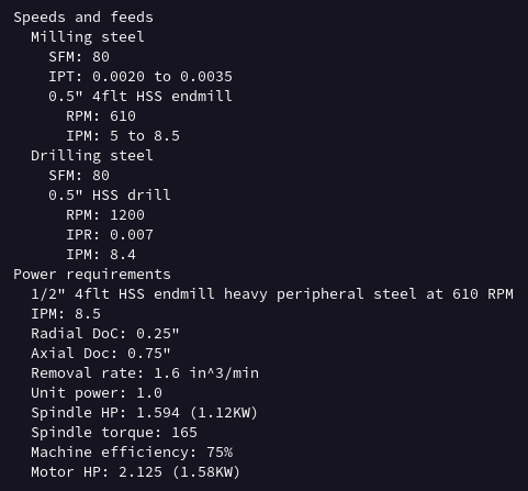
Here are my current numbers for target speeds, feeds, and power:
This is my first attempt at calculating power for a new machine design so if any of you have more experience and want to weigh in then I’m open to suggestions.
There seem to be a couple of common spindles like this one from RATTM that have a BT30 taper and ATC but they all seem to be designed for higher speeds like 15k to 24k RPM, presumably for softer metals and plastics. For steel I want more like 600 to 1200 RPM.
There are also a few kits like this and this that can be belted to external motors so perhaps I could use a motor with the right power curve for steel.
I wonder whether it’s too much to hope that the enclosure lower the cutting and motor noise to ~60db, or around the level of a regular conversation. With the air compressor nearby and the fans running, it may be a pointless goal.
I went back and re-read the thread, and saw that you were considering both flood and mist coolant. With it enclosed, is there any reason not to use only flood? Given flood coolant, would the air compressor be needed? If only for a pneumatic ATC, you could easily get away with a quiet compressor, right?
You have more experience than I do, but my manual mill isn’t all that loud and doesn’t typically inhibit conversation, so not sure why an enclosed cutting area would be any louder.
With a slower, higher-torque motor, what fans will be running?
When correctly cutting steel the noise from the tool and part aren’t terribly loud. Ideally, it’s a low pitch thrum. So, I’ll just always nail my speeds, feeds, and fixtures.
For the air compressor, I was assuming that something like the obnoxious 2.5 gallon pancake compressor I currently use (as little as possible) would be necessary. Maybe that’s a bad assumption. I’d like an air gun to blow off the fixture and part before swapping in new stock but I have a little handheld electric blower that could work. If air it is only used by the power drawbar then perhaps I can find a quiet compressor.
I have yet to find a low speed spindle with an ATC-compatible taper for less than $4k, though. My best choice so far is an unpowered head kit driven by a geared-down motor connected by belt. That’ll need some sort of cooling, air or water.
The electronics cabinet will need fans and the steppers make more noise than I’d like when they’re rapiding but maybe I’m incorrectly thinking about the noise levels of the motors that move the heavy beds of the big machines.
My 25G 175PSI compressor is enough to keep up with kool mist, but I don’t think I’d use a pancake for it; it might exceed its duty cycle.
The belt-drive spindle motor on my PM-30MV is passively cooled. For low RPM units I think that’s normal. Here’s the kind of motor that it shipped with (2HP, three phase) not including a VFD):
It’s pretty easy to cut custom v-goove pulleys for whatever range you want to run. I did that for my Z lift; I just ground a lathe tool until it fit nicely in an existing v-groove pulley groove, measured the pitch, and then cut to fit.
The stepper controllers you found say that they are quiet. It looks like you expect to put the steppers inside the enclosure anyway?
I wonder whether three phase AC motors need less cooling than the stepper motor I would use to rotate the spindle. *adds another research topic to an already long list*
I would like the axial motors to be enclosed but not in the same space as the coolant. I’m currently playing CAD Tetris to see where I can tuck them.
I’m a bit confused about using a stepper to rotate the spindle?
If you enclose the steppers, that’s where I’d worry about cooling. Steppers are always pulling their whole configured current, either through a single coil at a full step, or split between coils when microstepping. (Some advanced controllers like TMC can have a lower idle current and I guess that would work in a mill when you close the loop, but that’s just a separate configured current.) If you supply 48V to a stepper and configure 4A of current, by ohm’s law you will dissipate 194W of power (practically all as heat from the stepper). By contrast, a servo can be much smaller and pulls only the current needed to change its current position, and so dissipates correspondingly less heat.
When I mentioned servos, you went straight to Clearpath, which I understand are great, but they aren’t the only option. ODrive used to be open source, but I think is still high quality at any rate. Also, here’s an open source controller for three-phase servo motors:
I don’t expect this to control a spindle and I don’t know whether they have calculated its max current capacity or design voltage, but they are using it to drive a farm robot around, so it’s definitely beyond what you would need to turn ball screws.
Youtube decided this morning that I needed to watch this Clough42 video. $100 servo. Does require Windows to do parameter tuning; protocol clearly needs to be sniffed…
I’ve watched Clough’s video series on setting up a control cabinet and it was helpful for wrapping my head around some of the details that weren’t obvious to me. The $100 servo video is now playing.
While I have a fair amount of experience running machine tools, other than playing with hobby servos this is my first attempt to design and engineer a motion system, frame, spindle configuration, etc. This is definitely a run before I crawl situation. From your comments it’s clear to me that in this context you have more experience and information than I do so I appreciate your advice!
To make conversation a bit easier, I’ll put together a tight post with the current state of the criteria, design, and BOM so that we can tear it down to the studs and rebuild. Hopefully today.
My motion control experience: Two build phases of an OX-inspired CNC router, a currently-non-functioning CNC mill conversion of a mini-mill (was previously smoothieware-driven, and I want to move to LinuxCNC when I resurrect it), a bunch of 3D printers including an almost-from-scratch and a completely-from-scratch build, and a nearing-completion laser cutter. So I have some, but not as much as I’d like. Lots more second-hand.
Given that I decided to start my laser experience with a completely from-scratch unit with a motion system I haven’t seen before and outside dimensions of 1580x1080x1000 mm I think that "run before I crawl’ is my modus operandus.
I made the mistake of backing the Tarocco Crowd Supply crowdfund because open source, but it turns out that it can only build with a Windows-based toolchain and has been basically abandoned. So I have a bunch of brushed DC servos with encoders sitting around with boards that aren’t particularly useful. Was going to use those for the laser cutter but the first one died quickly in testing, and I lost enthusiasm and redesigned my hardware for steppers for now.
I’ve been thinking about changing my X table feed on my PM-30MV to servo drive, and did a design iteration on Returned Energy Dump board — requesting design review for that purpose — but I haven’t pulled it apart to figure out space constraints to figure out what motor and controller I could put in there, let alone worry about maybe also putting a RED in it somewhere, which is why I haven’t built the RED yet.
You would of course gear it down if you used something like that. And they make it in different lengths with different amounts of torque. But it might be helpful as you play CAD tetris to have an option with a different shape?
In the latest Clough42 video (around 19:45) he mentions in passing that his electronic lead screw motor died and in the comments he confirmed that it’s the $100 servo. So, it might have a short life.
Linking to our conversation over on Mastodon, where Taylor mentioned another open source controller under development that’s a closer match for a machine servo controller, and is inspired by their work.
At this point, it’s still alpha with needed changes, but it looks interesting:
However, it doesn’t look like it has an option for using the position sensors integrated into the body of the servo. It’s clearly designed specifically to screw to the back of an open BLDC motor, not something to put in a mill environment. So it would require some redesign to be usable in this role.
I love that this is happening. That said, I’m enough of an EE novice that it feels like too large a project for me to adapt the boards and SW. Maybe when it’s Spring and I’m out from under the gray dome of doom (AKA Seattle Winter skies).
Yeah, I don’t know whether my skills would be up to this challenge either. It’s at least fun for me to think about though.
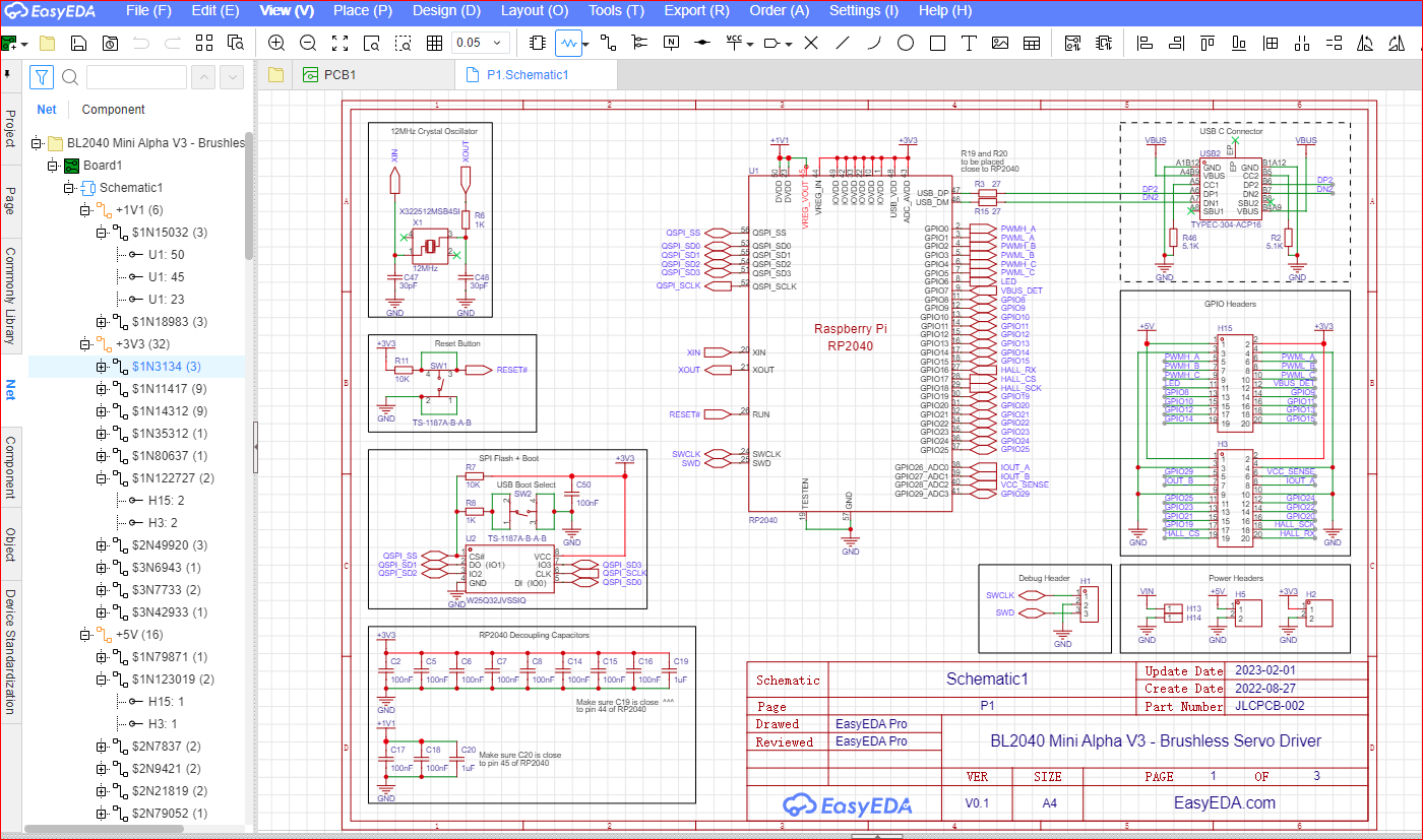
I’ve been reviewing the schematics for the current Twisted Fields controller. They added a whole second microprocessor and I think it owns at least CANBUS and E-stop comms/control. I think that’s not too hard to drop here, but because the schematics very heavily depend on named nets and draw very few wires, I’m finding it hard to trace with easy confidence. Of course I do the same with my own circuits to avoid a mess of wires on the schematics!
Don’t know if you are aware, but if you open the “net view” all the connections for a net are shown and when you click on one, it will target (red crosshairs) that item in the schematic.
I found this helpful tracing stuff when the nets are drawn using the port indicators vs wires.