It would be great if there was one single right answer. Unfortunately, this is not as cut and dry as a single answer or resource.
Let us look at the terms that we machining guys see often and dive right in.
Feed rate: This measurement is how fast one moves the tool against the workpiece. If we are on a lathe this is simply how fast we turn the tool on the workpiece per revolution. On our mill though we need to think of the revolution on our spindle and how many flutes are on the cutter, as each flute is a cutting edge. Ever hear you can decrease spindle speed by half for twice and many flutes? This is related, although an approximation and considers a constant feed rate. Feed rate has dependencies on surface finish, slotting vs. finishing, max HP allowable from the spindle, rigidity of the machine, workpiece, chip load and cutting tool. The feed rate is calculated for milling as: FR = RPM x # of flutes x chip load. Here we would want to start at the end mill manufacturer’s recommended chip load. We now have two variables and one equation, therefore we will need more information to solve this equation, more is provided below.
What happens if we chose the wrong feed rate? Let’s say we are machining an aluminum plate with a single flute end mill. Let us also assume these two scenarios are at an identical spindle RPM. If our feed rate is too slow we will get a loud high pitch noise known as chatter. Here we are doing more rubbing of the end mill to the workpiece because the flute is not getting enough cut per revolution. Resolve by increasing feed rate, alternatively you can decrease spindle speed. Now, assume we chose too high of a feed rate. You will know very quickly, the work piece will move, the cutter will vibrate or break, and the chips will be huge if you make any at all and the cut quality will be less than desirable. Look at your chips, you do not want to be creating dust, nor do you want to be peeling off long strips of metal. A nice square chip relative to the cutter size is ideal.
Ever hear the old adage that machinist tune by ear? This is related. We do this ourselves on CNC machines. We will load a known rounded RPM and feed rate for a cutter. Run the job and watch and listen. If we have chatter (which is the better side to be on) we start increasing feed rate or decreasing RPM. We log this into our journal and now have an idea to start at for the next job. Note that chatter is typically more audible in metals, plastics and wood will have more visual indicators.
Example calculation:
eq. 1 Feed Rate (Inch per Min) = RPM x chip load x # of flutes
A quick note here, always watch your units. Information provided and used by end mill manufacturers, machinist and machines use both Imperial (Inches and feet) and Metric (millimeters).
First though we need cutting speed, and to know the tool we are going to use. Low flute numbers for materials like wood and aluminum, one to two flute, four flutes for things like carbon steel. Small diameter for detail and low power spindles, big diameter for roughing or removing the majority of material.
In this example we are going to use a single flute 3.175 (⅛”) end mill and be cutting 5052 Al.
In order to get RPM, required for our feed rate equation, let us use equation two below.
From equation two, RPM = 7727 rev/min , now we need the recommended chip load for our end mill. A quick net search chip load = .001 inch per tooth.
Feed Rate (Inch per Min) = 7727 x .001 x 1
Feed Rate (Inch per Min) = 7.73 inch per minute
Cutting speed: This is often a misunderstood term for milling applications and is direct for lathe guys. How so? On a lathe the tool is stationary and passes through a rotating workpiece. The relative velocity or direct speed of the stationary tool on the rotating workpiece is the cutting speed in this application. On a mill this is the speed the edge of the tool passes the workpiece and relates to both the machine movement and the rpm of the spindle. This is dependent on the material of the cutter and material being machined. CS = RPM x Pi x diameter, typically we can make known the cutting speed by a quick google search on the workpiece material, in addition we typically know our tool diameter as well, so this provides us RPM. In our Gcode applications the CAM typically does not request the cutting speed but rather the feed rate. Cutting speed will be provided in the tool once the workpiece material is supplied.
Example calculation:
eq. 2 Spindle Speed (RPM) = Speed (Surface Feet /Min) /d x 3.14
We are trying to find the spindle RPM for our example below equation one.
d = ⅛” = .010 ft
Surface speed listed on the net for 5052 Al. = 250 ft/min
RPM = 250 /(.010 x 3.14) (Note what units cancel)
RPM = 7727 rev/min This is reasonable.
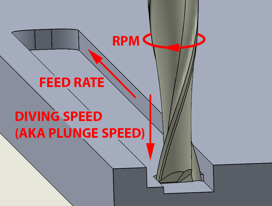
Fig. 1
Chip load: or feed per tooth is a number provided by some end mill manufacturers. Think of your end mill and the cutting edge. Turn that on a workpiece one revolution and the thickness of the workpiece that is cut off is considered the chip load. There are several factors that go into this selection but most are with the manufacturer, it can be calculated if other variables are known, CL = feed rate / (RPM x flute number). Chip load is related to feed rate we see from this equation so we can think of the example above about rubbing or removing chunks. The right chip load will keep heat down and give you a great surface finish. Alternatively note we are simply modifying equation. When working in imperial consider a chip load of .001 to .002 inch per tooth to be mostly acceptable.
RPM: In lathe work this relates typically to the workpiece revolution per minute. In the milling applications this relates to the spindle speed. New guys typically go for much too high a spindle speed on their first jobs. This is not a problem, you will get chatter, poor surface finish, and excessive tool wear, but it is better than snapping the tool off due to too low an RPM. Look for the chatter with too high an RPM during a job and slowly decrease RPM till it goes away. This method is not easy. There is a perfect balance, think of a parabolic graph extending up and down the Y. The point your machine will like is right at that peak and it is not a plateau, too high or too low and you start falling down either side… make small adjustments. If your spindle is bogging down go up, chatter, go down.
Workpiece material: This is typically referring to the base material to be machined. When the material is requested it is important to make sure you know what your material actually is. Carbon steel, is it A36 or API 2H? Aluminum, is it 6061 or 5052? Wood is it a balsa or pecan? The material has a related hardness, typically quoted a HB (brinell) or HV (Vickers) or HRC (rockwell) in metals. Woods are slightly different sometimes rated by a Janka hardness test. Your end mill choice, feed rate, chip load, and about all other variables relate to the hardness of material. Ideally pick your end mill for the hardness of material based on suggestions from the manufacturer.
Spindle speed: See RPM above
Depth of cut: See figure one. On a milling machine this is how far the end mill goes into the workpiece in the vertical direction per pass. CNC operations will have the end mill enter the work piece to the specified depth then start moving horizontally at the feed rate (less we are ramping). Most end mills we purchase for our DIY CNC machines are center cutting, we won’t dive into that here, meaning they will dive into a material without issue. A large depth of cut should be reserved for larger diameter tools and visa versa for small tools. I.e. you can take a full millimeter depth of cut with a 4mm end mill but you certainly would not make it anywhere with a 1mm end mill trying to cut a 1mm depth slot, meaning depth of cut and diameter are related.
Diving speed: Diving into your material has a specific feed rate as well, we know… more unknowns to fill in. The feed rate here we have found is not as important, why? Well as stated most end mills will dive without issue even at improper feed rates. Too slow and no harm done, on metals you may chatter, next operation speed this up. Too fast and you may not know it till it is too late. We will typically use 10% of feed rate if we are in a situation we must guess and 50% in soft materials like wood. Depth of cut is where cutting speed and feed rate come together are can be related to chip load.
Width of cut: The width of your cut depends on what you are trying to do. When we lay out a work piece in our cam software we may be performing several operations, drilling, profiling, slotting, etc. Consider slotting, if we want to cut a shape out of sheet material we will be slotting the outer profile of our final piece. In this situation our width of cut is equal to our tool diameter. If we want to go back and performing a finishing pass on our slot cut we will be only using the portion of the cutter hence our width of cut would be a percentage of our tool diameter. Slotting and profiling will have different feeds and speeds. If you are trying a feeds and speeds calculator most will ask what width of cut you are making. In general, as width of cut decreases feed rate can increase as chip load will go down as we are only using the side edge of the tool.
Fig. 2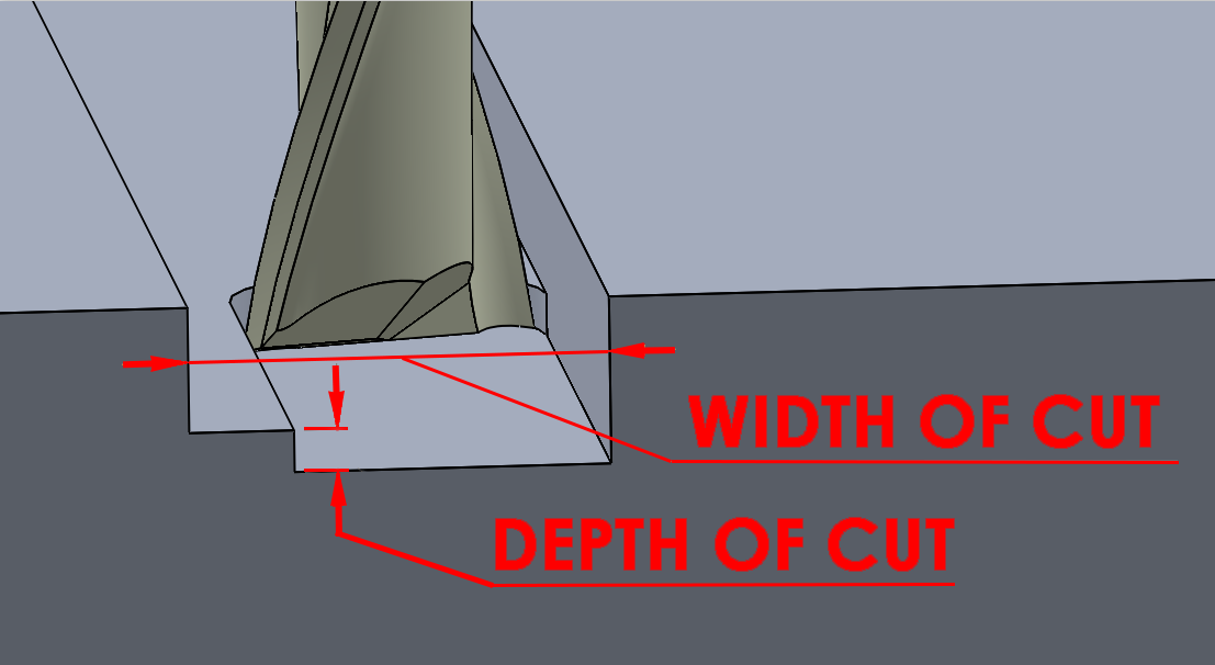
Cutter material: This term relates to the material of the end mill in milling applications. There is a large selection to choose from and it can get confusing what to choose. In addition end mill manufacturers will also offer various coatings. We want to select our cutter material based on out work piece material. If one is working on soft materials there is no reason in purchasing small grain cemented carbide end mills, conversely there are times when in hard materials this same end mill can be an issue. Cutter material controls tool deflection (also controlled by machine rigidity). A high tool deflection will provide an undesirable cut presentation, opposite, too hard of a cutter and a loose machine will snap the rigid tool. HSS is abbreviation for High Speed Steel, this tool will allow some deflection prior to breaking. Carbide is one of the hardest end mills we use and is our go to on the R7 for most applications. Testing shows cobalt falls somewhere in between. Most speeds and feeds calculators base everything off tool deflection, this is kind of the answer and all variables inputted go to gain the correct feeds and speeds for the required tool deflection.
End Mill diameter: This will be the cutting end of the end mill. Note special attention when purchasing end mills, several measurements are provided, total length, cutting length, shaft diameter, and cutting diameter. As noted above almost all calculations depend on end mill CUTTING diameter. We advise to always place a new end mill into your machine and do a slow dive into a material and measure the hole. We have found the smaller the end mill the more variance there is in reported cutting diameter vs the actual. There will be times when you need a long cutting length end mill. Perhaps you’re in ½” material and are profiling, here speeds and feeds can be reduced. The longer the end mill the more opportunity for deflection.
Holder to cut tip length: This is a physical measurement from the collet that holds the end mill to the cutter’s tip. Required for tool deflection calculations.
End mill cutting length: The measurement from the cutting tip to where the flutes stop. Always important to consider your base material thickness when selecting your end mills. One would like an end mill cutting length only slightly longer than the thickness of one’s work piece.
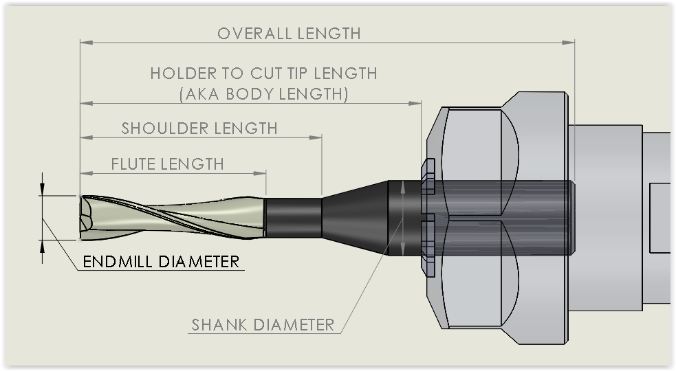
Fig. 3
Cut profile: As described above this can be profiling or slotting or sometimes even a canned or pocketing cycles. Important to note cut profile relates to deflection there for is related to speeds and feeds.
Tool type: There are a number of end mill profiles. A square end will be used for slotting and will typically have a square end when viewed from a side profile. A radius cutter will look like a square end mill but it will have rounded edges. One use for a radius corner cutter is when one is machining a pocket and wishes to remove a sharp edge stress concentration. Ball nose end mills are good for 3D type profiling, for instance if you wish to put a rounded cylindrical object in a flat piece a ball nose will provide a nice rounded machined surface. Some feeds and speed calculators will take the tool profile into account.
Coating: Tool coating is applied to end mills for a various reasons but mostly it is to reduce friction therefore reduce heat and degradation.
Upcut and downcut: This refers to the helix direction. Use an upcut to remove chips from the cut path. Use a downcut in soft thin materials that will want to peel up while cutting, such as thin lexan or wood.
Helix Angle: Helix angle refers to the angle at which the flutes twist up the end mill. A zero degree would be considered a straight flute end mill, good for wood applications where tear out can be an issue. The helix angle will be related to waste removal. A high helix angle will remove chips faster but leave less cutter on the workpiece. 30 to 60 degree helix angles are common.
Surface finish: This is a description of what the cut profile looks like post machining. We all want that mirror finish, but at times there are cost associated with it. A mirror finish has very low material removal rates, related to a finishing pass, while high material removal rates, roughing pass, typically have a very poor surface finish. Production machining will typically have both. A rough pass will be made with a large diameter cutter and a finishing pass will be performed after to give the mirror finish. When diving into speeds and feeds one often decides if this is for a roughing or finishing pass. As a generality roughing passes are high feeds and slow speeds (RPM) whereas the finishing pass will be slow feeds and high speeds, but again we are limited by tool deflection.
So with all this information, what’s the right answer? There are several free online feeds and speeds calculators, there are also fancy calculators you can pay for. What we hope you have seen from the above is the variables are numerous. One can use the feeds and speeds calculators and they may get you in the ballpark but not in a good seat. The right feeds and speed for your machine are good for your machine. Variables such as rigidity, clamping method, drive systems, work materials, machine mass and tools all donate to the feeds and speeds. Keep a log of what works and what didn’t. Try different tools and materials, practice here truly does make perfect.
One last note, don’t get frustrated. You are going to break tools, you are going to waste material these are part of the learning processes. The advantage we have as DIY CNC users is once we have a the perfect file with great feeds and speeds its ours forever and no more tuning or guessing will be required for that tool and material. Once you have began to understand feeds and speeds it will be amazing where this will apply, even simply drilling a hole with a cordless drill, every tool and work piece have a perfect feeds and speeds.
We are working to have guys from the community feed in what they know so we can provide the new guys a reference. Have something to add, or need a starting point, check this out: