Unable to align mirror 2 in the horizontal direction when testing front and back locations

I just got a K40 which hasn’t been used for 2+ years and I never used a laser cutter before. I knew something wasn’t right because at 100% power and at 1 mm/s it wouldn’t cut through 1/8" MDF (even with multiple passes).

I’ve narrowed it down to alignment. With mirror 1, the beam is coming into the mirror and out of the mirror at the center. I use Scotch tape to verify this. Is it safe to say that the C02 tube is aligned correctly?

With mirror 2, I used shims underneath the rails to get the laser dot vertical before is enters the mirror. This is when the machine is at the origin (0,0) and also at the furthest distance from the back of the machine (0,12"). The problem is that at the origin, it is dead center (X and Y). When it is at the front of the machine, the Y is fine, but it is off in the X direction by about 1mm.

How do I adjust it so both dots are in the same location and in the center?

https://forum.makerforums.info/search?q=laser%20align

Since there are a lot of search results there, maybe a good start would be one that @cprezzi linked to. In:

he linked to this video:

2 Likes

Thanks so much for both of those posts.
I think the second one makes it look sooo easy though :slight_smile:

All four corners of the bed are now shooting directly in the center. Well, 1 corner is still about 1mm up, but the other 3 are shoot through the same pin hole.

Even with all of these adjustments, it still takes about 10 mm/s with 25% power to cut through a business card (at various different heights). Correct me if I’m wrong, but it should but though something like that at 100 mm/s with about 10% power? Could it be the laser be going (or went) out on it? Or possibly the mirrors?

For the tube it would be more diagnostic to have the mA draw of the tube at a particular power setting. You would need to put a ammeter in the circuit to see how much current the tube is using. If you need help with that setup let us know.

Also need to check your bed height. If your piece is out of the focus point of the laser it can drastically affect the cutting performance. For cutting your height should ideally be set so the focus is halfway into the surface of the workpiece.

Also check that the lense is in with the curved side up.

Do you have an air assist set up? If so make sure that the beam is exiting through the middle of the nozzle and isn’t clipping the edge.

I do have a Clamp Digital Clamp Meter and a regular DMM. What power setting (Power Max% and Power Min%) should I use?

For the height, I did straight lines at each millimeter between 17mm and 30mm. This is measuring from the top of the wood to the bottom of the laser (but not to the lens). See attached image.

The curve side of the lens is facing up. I believe that it is a stock system, so I’m assuming it is a 50 mm lens.

For the air assist, I’m using an Aquarium pump for 10 to 30 gallons size tanks. I did verify the beam is exiting the last mirror in the center of the tube, so it should be in the middle of the hole.

Here is what I got when using the Clamp meter with a setting of 200 ACA

image

OK, so how are you setting the power on your machine? I was assuming you had a digital control panel on your k40 but I’m confused by your use of max and min. @donkjr thoughts?

I don’t know were the clamp meter is placed and what type it is. I doubt a clamp meter will measure the tube current accurately.

Also do not understand min-max settings and the last columns data?

I advise installing a meter that can read (ma), in series with the tubes return (cathode). Then plot tube power setting vs tube current.

Since the power is so drastically reduced I would remove the air assist nozzle and see if it cuts better, verifying the beam is not being internally reflected by that housing.
Alternatively, you can fire with the head held at a fixed target on the bed, leaving the target and head in the same place, move the bed up/down and fire again to see if the burned dot moves. If it does, the beam is not traversing through the objective lens perpendicular to the surface.
You can also inspect the inside of the objective lens housing and see if there are burn marks.

Do I understand your FL test correctly, you burned lines at different heights and looked for the thinest one?? It may be hard to find the right point with that method especially since the head is in differing x-y positions??

I suggest doing a conventional ramp test where the target is on an incline and one horizontal line is used to find the FL?

Picture of control panel?
Picture of LPS connectors?

1 Like

I’m sorry for the confusion about this. Through a friend, I bought it from a guy who hadn’t used it in over 2 years. He didn’t know anything about it and said that it was a K40. The one I have is here:

https://www.toolots.com/20-12-50w-co2-laser-engraver-and-cutter-usb-port-fda-certified-kehuilaser-kh-530.html?cid=1469602926&gclid=Cj0KCQiAsvTxBRDkARIsAH4W_j_C8TxPz0Tx9v1wW4CkgFxs7NE7V3JmKXOYaHeTA4yDYdhZNhJCUYkaAiQiEALw_wcB

On the unit itself, I don’t have a the power adjustment button nor is there a meter showing the power.

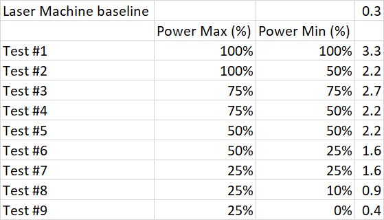
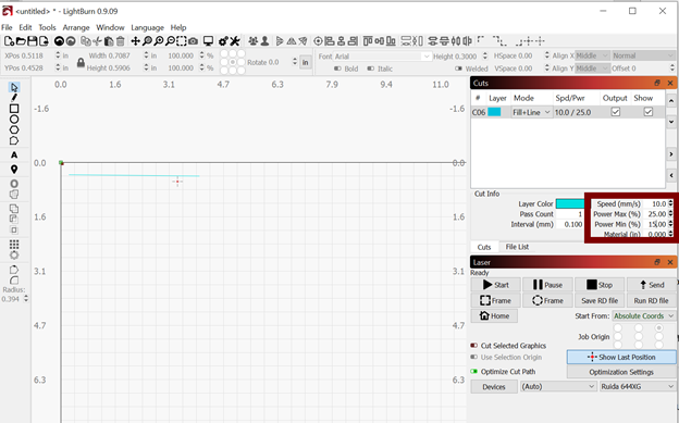
I have been using Lightburn and I was using it to control the speed and power. From my research, the ‘Max’ power is used for the majority of the time, but the ‘Min’ power is used in corners so the material doesn’t burn when the laser changes directions.

image

For the chart I made, I was using the power cord that goes into the entire unit, which includes the little LCD, external fan, gantry motors, and the C02 laser…. I used a clamp meter around the individual white power cord, the black and green cords were outside the clamp, I’m assuming the units are amps. But since I was measure a host of other items at the same time, I don’t think that it was a valid test. For comparison purposes, my wife’s hair dryer was 10.7 using the same clamp meter setting.

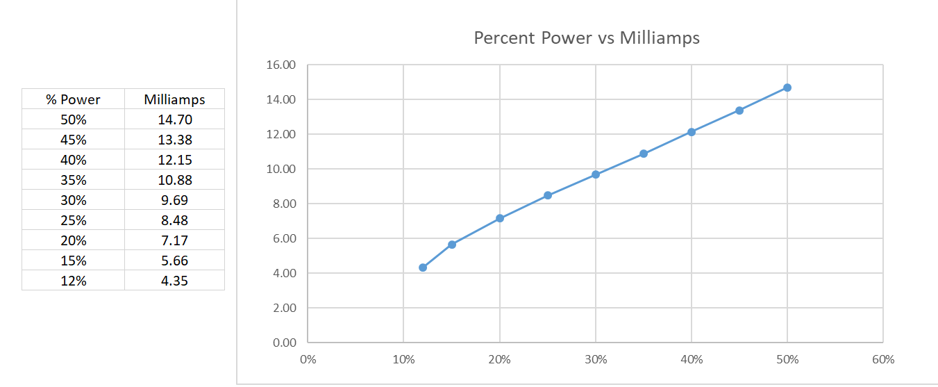
I’ll have to get my multimeter and put it just on the tube and make a chart of power setting vs tube current.

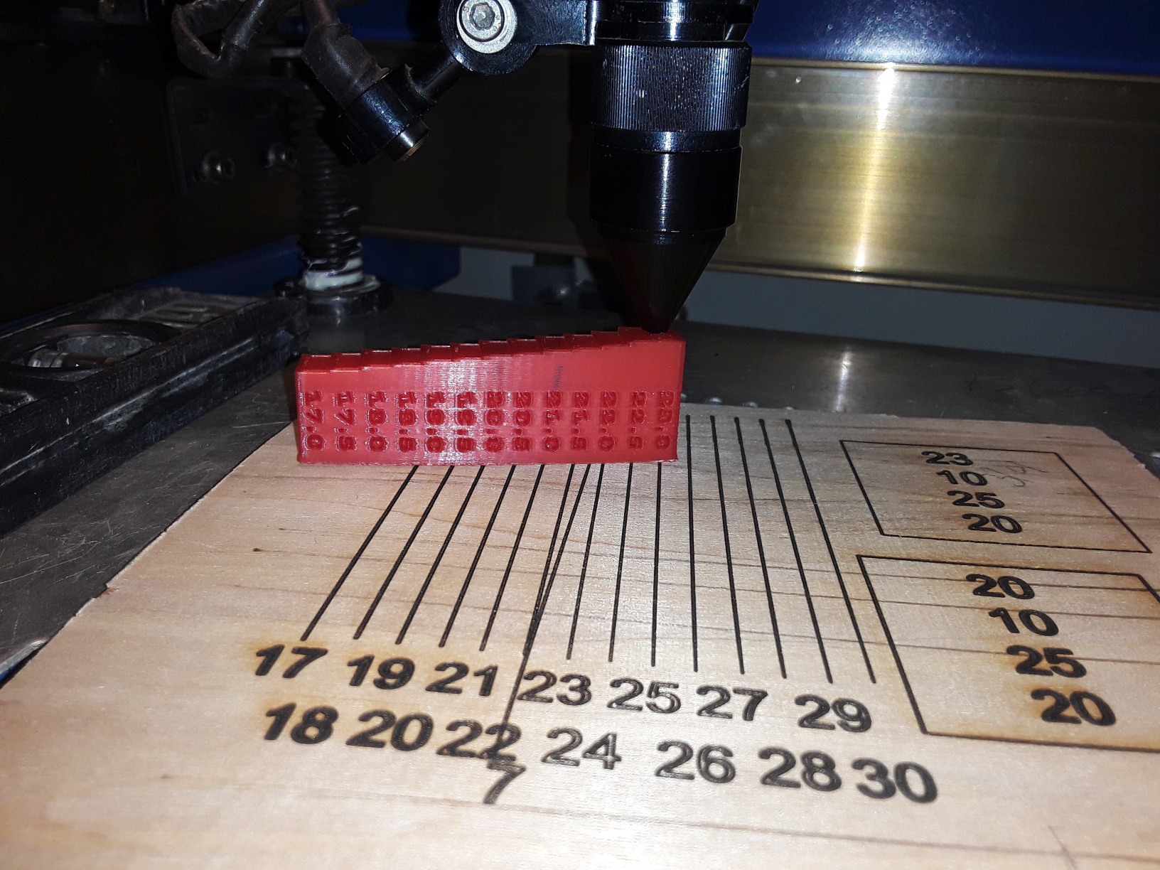
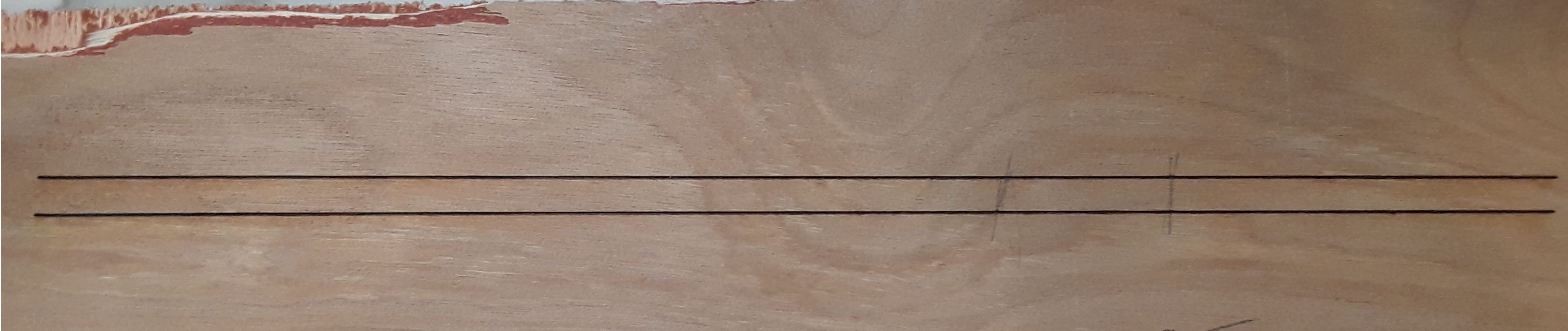
For the focal length test, originally I did the ramp test and saw where the line was the thinnest, it was somewhere around 24. To verify this, I did the lines at various heights and looked at the results. There was burning at the shorter distances and at the further distances it was more out of focus.

I’ll also take out the air assist nozzle and see if it has any effect.

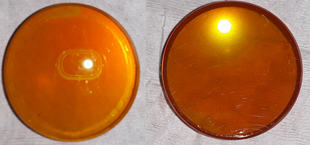
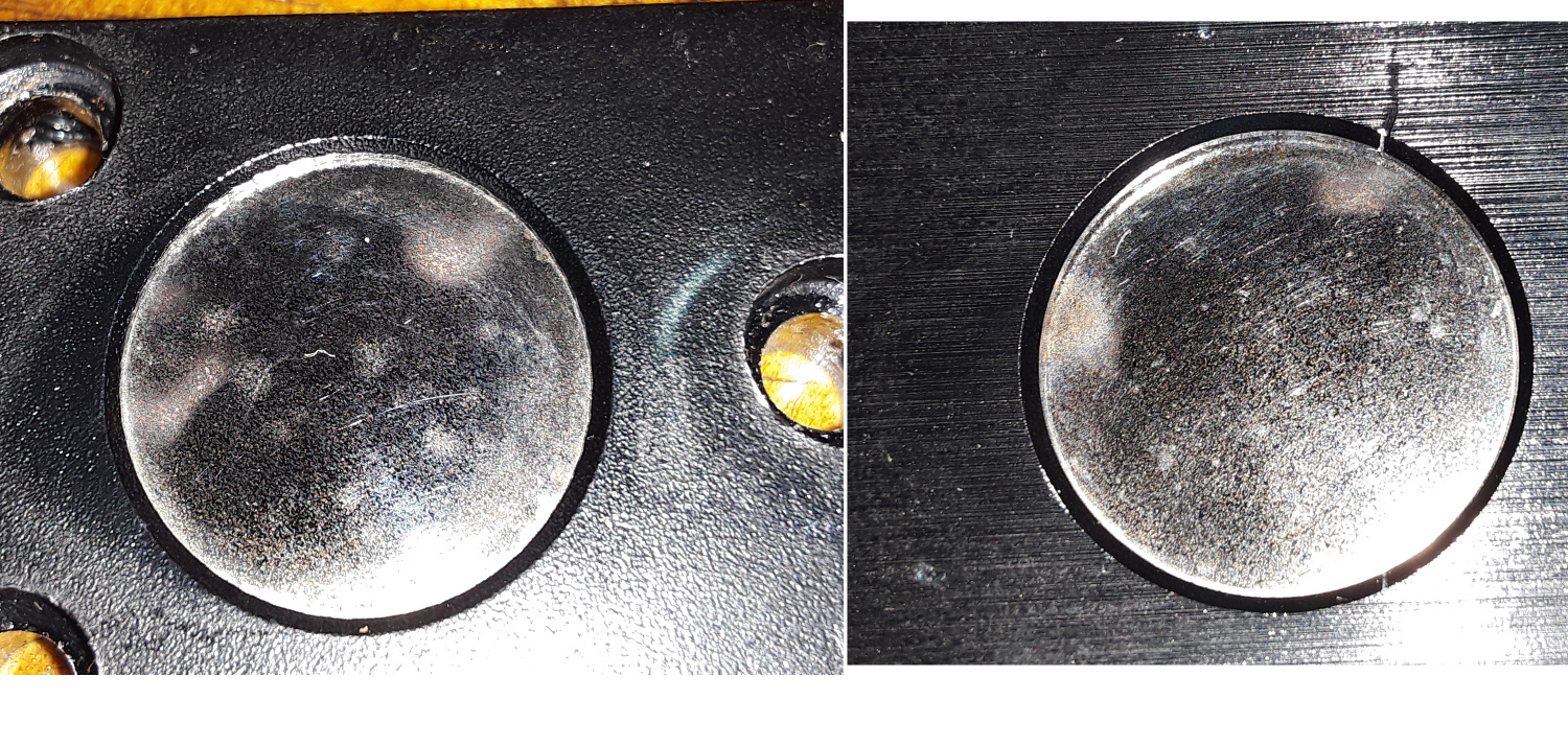
Here is the front and back of the focal lens. I didn’t see any burn marks, but there are some slight scratches on the concave side.
image

Here is what I got when I put my multimeter inline with the tube. My multimeter wouldn’t go any higher then 50% but the lower half is pretty much a straight line.

A clamp ammeter might not be super accurate for milliamps, but also and especially AC amps isn’t the right setting for measuring DC amps. I’m pretty sure there are clamp ammeters that don’t even have a DC amp range, though mine does. I don’t expect milliamp accuracy from my clamp ammeter.

The above chart I did with a multimeter using the mA setting. I put it inline between the tube and the power supply. So I think I finally got that part correct.

Ok those readings look fine. You would not want to run higher than 50%. 15mA is the recommended limit for best tube life. It deviates from linearity at the low end because you are getting close to the ionization threshold of the tube.

So as a reference, if everything is set up correctly, you should typically be able to cut through 1/8" wood with settings of around 8mA power and 10mm/s speed.

Can you provide a picture of your mirrors? Just want to see what condition they are in.

I can only assume that I’m in the market for new mirrors. :slight_smile:
And probably a new focal lens also?
Any links on Amazon of good mirrors?

Yeah, those mirrors look toasted, may be your issue. Your lens is probably fine. Some light scratches won’t have much of an effect. For replacement mirrors and lens I would recommend Cohesion3d. The people who run it are long time members of this community and sell good products at reasonable prices.

https://cohesion3d.com/product-category/optics/

Thanks for all of your help. I’ll update when the new mirrors get installed!

2 Likes

I got the new mirrors installed and realigned. They helped a little, but at around 8mA power and 10mm/s speed I can barely cut through a business card…

Below is the ramp test at 8mA power and 10mm/s speed that is .125 thick. I think it is most narrow where I drew the pencil marks, which is right around 50mm from the focus lens.

Even though the milliamps look correct, could the laser tube still be bad? Could there be an issue past where I measure it at the end of the tube?