Suspended laser bed? [Spoiler alert: No...]

Spent quite some time tonight adjusting each of the lead screws and guide rods to be parallel to the uprights to within .25mm which seemed to be my limit of precision while trying to hold large calipers in place. I expect to have to improve the alignment a bit more, but maybe after installing a belt.

I ran each screw up a few millimeters at a time, alternating around all four corners. Racking more than about 5mm caused binding, so it was a slow process to get it so that the bottom of the bed frame was 80mm above the C beam that forms the base of the laser box all around. But I got there in the end.

I ordered belt since it turns out I don’t have one long enough, so I have a few days to design and make a motor mount. Since I don’t yet have a design in mind, I might lose my race with myself. :relaxed:

The bed feels rigid, and I didn’t perceive movement when I leaned on one corner of the bed frame with most of my weight.

2 Likes

I am curious. All the adjustable beds I have seen only use lead screws and do not have a rail or linear bearing for stability. Just curious what your thoughts were for adding the second linear bearing. It seems that you will have more of a problem with binding.

Very sensible thinking!

My expectations come from experiencing building, re-designing, and designing 3D printers. There, you will find very obvious artifacts in the print if you try to use a lead screw as a combined lead screw and linear constraint. I don’t know that I actually need to do any of this, but I’ll describe how I got here.

Initially, the rods were entirely necessary for alignment when it was suspended from UHMWPE line. So the question was whether to remove them from the design when moving to lead screws. I’m not sure whether I would have added them in the first place if I had not been trying to suspend the bed in the first place.

Lead screws are made of 300-series stainless steel; linear rod is hardened steel, so lead screws are more flexible than linear rod even before accounting for the smaller effective diameter of the internal thread diameter. The lead screw nuts are a loose tolerance fit; if you thread a loose nut onto a piece of lead screw you can feel the loose tolerance in slight wobble. Finally, the screw is not necessarily as straight as the rod in the first place.

Straightness doesn’t matter if you only use the Z axis to get a flat part into focus and are never driving it while lasering, and if you are never putting a lateral load on the bed, the flexibility and loose tolerance probably also is no problem. So for typical use, this is probably fine.

However, I can think of two reasons; one practical and one theoretical, to keep the linear rods. The possibly practical consideration is that this has a 1500mm X gantry, which means that it has substantial mass to shift in the Y direction. The frame is lighter than a typical steel laser box, and the larger the ratio of gantry mass to machine mass, the more the whole machine will react when the gantry moves. I would expect that shifting from engaging the front lands to the back lands in the nut would be enough shift to create visible artifacts on parts. The entirely theoretical consideration is that in one imagined use, I might first use the OX to route out a relief, and then engrave on that surface with variable height and want Z to track to keep in focus. I have no plans to do this, but the idea of someday being able to do that and keep good alignment throughout is intriguing. It’s not likely that I’ll ever do this, but it’s nice to think that I haven’t closed the door on the idea.

If I have any problem with binding, I have an alignment problem. The question then is whether I have the skills and tools to resolve the binding problem. Since the screws rotated reasonably freely when the bed was aligned well, I think I’ll be OK here. One I have a belt in place, I plan to loosen the upper attachments for the rods and the rear two screws, run the frame as high as it can go, and then tighten the upper attachments. (I already aligned at the bottom.) If the screws still bind, I can loosen one of the front screw attachments as well to fix side-to-side alignment.

I could reasonably go with one linear bearing on either side. So if I have problems with binding I could take off a pair at opposite corners and simplify. But this huge bed frame (850x1500) isn’t really stiff, so I’ve been taking the approach of considering each corner somewhat independent. Logically, I should be lifting at three points not four, since three points determine a plane. If the bed were stiff, I would probably do that. But it’s not stiff enough for that; I’ve measured I think approximately 5mm of “potato chip” deviation from flatness earlier.

3 Likes

I spent some time trying to figure out whether I could/should pass the belt through into the LV side of the back, but decided that was a bad idea. I decided that a motor mount box inside the cutting chamber, with an angled sheet of aluminum protecting the belt from the laser if necessary, made more sense. So here’s my current design, as far as I’ve gotten:

This box holds a NEMA23 motor and two idler pulleys, and the belt is tensioned by moving the motor which is attached through the slots on the top. The box can be adjusted up and down about 10mm to help align the belt (the mounting slots on the left side). I haven’t designed the idler pulley holders. I’ll probably print something that press-fits onto the same 608 bearings I’m using elsewhere; I have 4 left. Then I’ll make standoffs that screw firmly into the round holes on the top.

It can be 3D printed (upside down); that’s why the step is a 45° overhang. The bottom is open.

The shell is 5mm thick, and I’ll be printing it at a high infill. It would be a lot simpler in metal, but I’m trying to make this laser something that could be built without a metal shop.

The FreeCAD shell support is still basically useless, I think. I had to extrude the shape and fill in the ends to get a shell. The FreeCAD forum basically says that it usually doesn’t work and you should use a workaround, so I did.

3 Likes

It took a couple tries, but it looks like I came up with a working idler post and race. As with all the other fittings for 608 bearings in this project I’m using crush ribs for a secure fit, and using the insertion tool I designed to push the bearing into the hole in the pulley putting pressure only on the outer race of the bearing.

I’m drying a new roll of filament to print the box. This roll is nearly done.

3 Likes

Printed the box overnight.

I didn’t check the diameter of the new filament, and I was printing all perimeters/shells, so there was no place for a little extra filament to go. I had two layer shifts from skipped steps as a result, and the last couple of millimeters printed spaghetti. I was lucky not to wake up to another ball of hardened plastic around my nozzle.

I cleaned it up, and this will be good enough for testing. I can print a new one (with compensation for filament diameter) once I’m sure I don’t want to change the design; at a quarter of a kilogram I’m not eager to throw away money and plastic on extra test prints.

2 Likes

“But Michael,” I hear you say, “where does the motor shaft come out? Where does the motor register to?”

That is an excellent question that will be answered in the second print.

I had happily attached the idlers to the box before I realized why I had had an uneasy feeling that I’d been forgetting something in the design. (This is the problem with doing CAD at the end of a long and exhausting day of work.)

I’m happy to report that PETG actually mills pretty nicely. I didn’t bother trying to use the DRO to mill a slot in a prototype. I just chucked a 10mm end mill in and made a centered rectangle 38mm x 50mm. Here’s the setup:

This demonstrated that the motor mounting screws interfere with the idler pulleys at least at the close extent of the motor.

Next changes will be:

  • 1.5mm deep 9mm wide slots for the motor mount screw heads
  • Actually model the 38.1mm slot for the motor
  • Measure shaft and pulley to make sure that pulley can engage with shaft and be lined up with idlers
  • Make some access holes for holding nuts inside the box for mounting the motor and idler pulleys, because what I had to do to get nuts inside the box was, well, just nuts.

Bonus picture: I’m using a dual shaft stepper with a handwheel mounted on the other side to make it easier to adjust the bed while I’m working on it, before I hook up power. The handwheel here is one I made on my lathe when this motor was installed on other equipment. I knurled it gently so that there’s enough knurling to hold firmly, but it’s not sharp enough to be uncomfortable.

If you look near the bottom, you can see blurry-cam nuts all the way down at the bottom of the box. There’s not enough room between the motor body and the nut faces to use a socket, so you can probably imagine how much fun it was to get those nuts installed!

1 Like

Here’s a top view:

  • Slot for NEMA23 motor (the… whole point of this box after all). This is a parametric design, so if I make the box wider and increase the length of the mounting screw slots, the motor registration slot will grow equally longer. Just change one parameter and the whole thing responds. :tada:
  • Recess for ULP M5 screw heads; 9mm wide and 1.5mm deep. Because this box prints upside down, in order to avoid generated supports I made a .3mm bridge in the slot that I’ll knock/cut out after printing. The box prints upside down, so otherwise that overhang wouldn’t print right.
  • Side cut-outs—note the triangular bottoms (top as printed) so that no bridges or support are necessary.
  • You can see a boss for the idler screw peeking out the underside of the top. What is that boss for?

Here’s a bottom view that shows the hex pocket in the boss to hold the M5 nut for the idler pulley captive, as well as the underside of the mounting screw slots.

2 Likes

Reduced extrusion rate improved surface finish as well as avoiding any missed steps. I clearly need to adjust my Z end stop (“elephant footing” visible and required cleanup) but it didn’t cause the print to fail. You can see the stringy bridging in the motor mount slots, too.

Here’s the other side, clearly showing the bridging in the motor mount screw countersink slots. That was a pain to clean up! I admit that I took the quick and easy route and just dropped it in the mill and ran an endmill around, but knife and chisel would have worked and just would have taken more time.

Close-up of idler pulley mounting screw captive in its boss. I used a magnet on an 8mm rod to align and press the nut into place.

From the top side, with the idlers installed:

With the motor installed — this was so much easier with the access holes at the sides.

Also, the access holes make it easier to move the motor. The belt is tightened by sliding the motor away from the idlers like this. Or, at least it will be after I make the belt!

I have modified the model to have slightly wider countersink for more screw head clearance, and added some chamfers and fillets, for easier cleanup for the next person, if any, who ever builds one of these. Or for me, if I discover that I need to make another change.

I now have a quandary. I put 20T pulleys on the lead screws. I don’t have any more 20T pulleys to put on the motor. I would get more torque if I replaced the 20T pulleys on the lead screws with 30T pulleys that I already own, and then I could put a 20T pulley on the motor. But it would be a lot of work to pull all the lead screws and I really don’t want to do it. So I think I’ll put a 30T pulley on this 3.2A stepper motor, and if it doesn’t have enough torque, I have a larger stepper that I bought because I thought I would need it for my OX upgrade, and turns out not to need after all.

If I change my mind and change out the pulleys later, I’ll almost certainly have to make a new belt.

4 Likes

I came to my senses and realized there would never be a better time to change out the pulleys on the lead screws. It was not that hard to remove the lead screws, swap out the 20T for 30T pulleys, and put it back together. I put one of the 20T pulleys on the motor.

I also realized that I want to have one more idler pulley to keep the belt away from the laser (I’ll put a shield over the motor, I think), and that will also give me more room to set belt tension by moving the idler pulley. So I’ll do that before I size and splice the belt.

Here it is so far; the third idler will go to the right and I can tension the belt by moving the idler closer to the motor box. If I had thought of this before, I wouldn’t have had to have made the motor movable in the box.

2 Likes

The sliding idler mount worked.

That let me pinch together a loop of belt and try running it, at which point I discovered that I made an arithmetic error somewhere and the motor mount box and idler are maybe 5mm too high. I had trouble getting a good angle to see it, but running the belt back and forth (with the lead screw pulleys loose) made it obvious. I must have omitted a number somewhere, so I’ll just go back and check the model.

Also, with the new idler, there is no real purpose in making the motor mount adjustable to slide the motor back and forth. So I’ll simplify and print both parts again.

I don’t like this particular black PETG. I’ve had some print artifacts that I just didn’t expect. Shouldn’t be a moisture problem; I just dried it and got 2 grams of water out. But the corners are “crunchy” with inconsistent extrusion, and I had the very unexpected layer shift and spaghetti before reducing the extrusion the other day. I could try increasing temperature a little; I’m printing at 245°C which at 80mm/s is maybe a little low. I could increase it 10°C and see whether that works better.

3 Likes

Oh. Somehow retraction got turned on in the slicer. Couldn’t possibly be any sort of user error… :rofl: I finally watched closely during the last print and saw what was going on. I let it finish because it’s just cosmetic, but now the mystery is solved. Once I realize that, I see evidence of it all over. You can see it in this picture of the new smaller mount:

I had to clean a random blob off this idler, but other than that, you can see that the screw head is still well clear of the idler:

The belt path is flatter now:

Here’s the whole system installed:

So the next question is: With the more compact box, will the laser hit it? Here’s where the 3rd mirror alignment tool comes in handy. I just installed it upside down, pointing down, and aimed it at the box. While I don’t plan to normally operate the laser over the box, it’s clear that a shield would be a good idea:

2 Likes

Another wonderful use for the laser alignment tool!

2 Likes

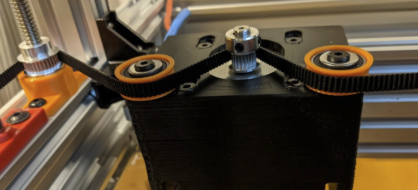
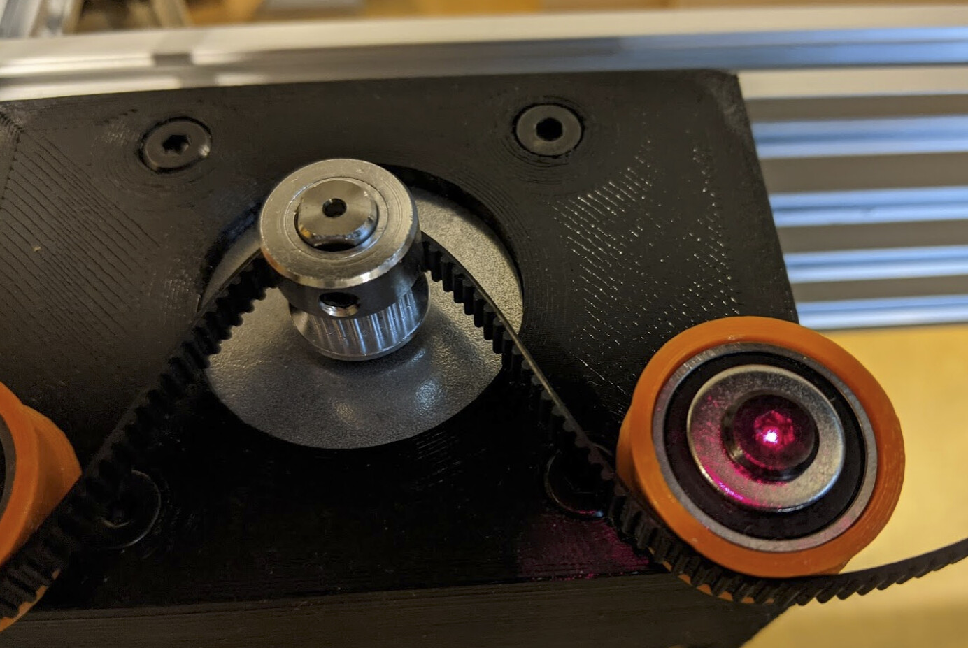
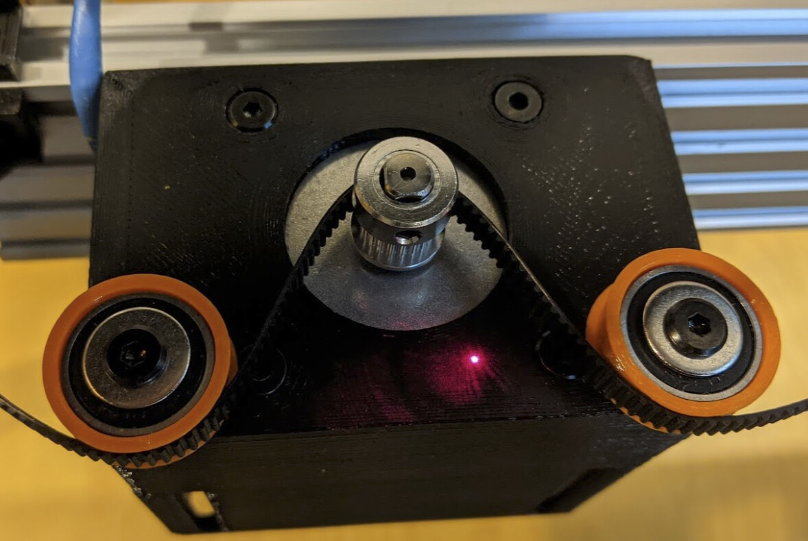
Tonight, I measured a loop around all the pulleys. I clipped it together with a cute little quick-grip and lined up an overlapping section about 20 teeth long (17, as it happens; the exact number of teeth didn’t seem important). I used silver sharpie to mark the overlap on the back side of one end of the belt, and colored all the overlapping teeth on the other end of the belt.

Then I used a fresh xacto blade to cut off all the marked teeth from the one end, and to slice off the back of the other end. I very carefully cut both ends down to the point where I could feel and hear the fiberglass cords, but tried not to damage the cords. I made sure that the teeth aligned without a substantial gap. (I noticed that a used exacto blade didn’t cut as well; changing to an unused blade made a big difference.)

Then I cut another short piece of belt a few inches long, and superglued it to a flat surface (in my case, scrap aluminum) with the teeth facing up. I put some cling wrap on top of the belt section.

Then, demonstrating that my mind wasn’t completely on the job, I moved over to my workbench where there was plenty of light to make it more convenient to work on.

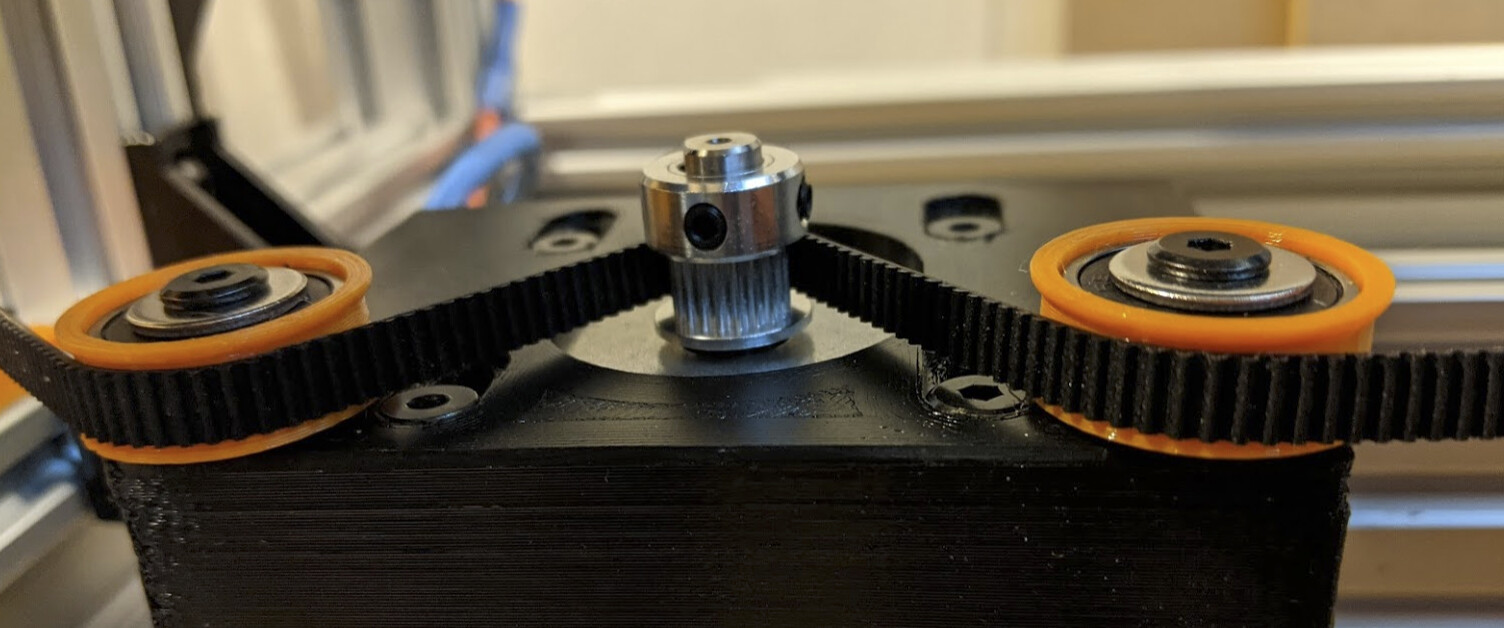
I made sure there were no twists in the length of the belt, and put the end of the belt with the back removed down onto the fixed belt segment. Then I put the end with the teeth removed on top of the other end, with just the prepared sections overlapping. I confirmed a good fit without significant gaps.

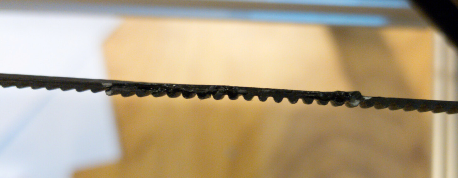
With both sides of the belt held in place, I lifted the top loose end (with the teeth removed, and put a layer of IC-2000 rubberized CA on top of the part of the other end where I had removed the back. I laid down the other loose end on top, made sure the sides were well aligned, put another layer of cling wrap over it, and held it tightly clamped together (another piece of scrap aluminum) for a couple minutes.

The joint is a bit stiffer than the rest of the belt, so Black Witch Neoprene Adhesive would probably be a better choice.

This was the point where I quit leaving 3/4 of my brain engaged on work stuff and started really paying attention to what I was doing.

I finally realized that I now had a topological problem.

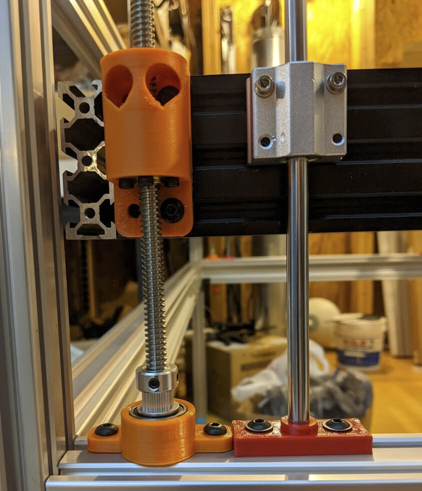
This belt had to go around four lead screws and four guide rods.

Next time, I might just start over and make a new belt inside the chassis, but this time I carefully removed, inserted the belt around, and then replaced all eight, one at a time.

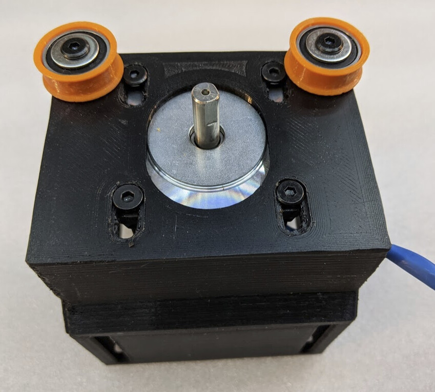
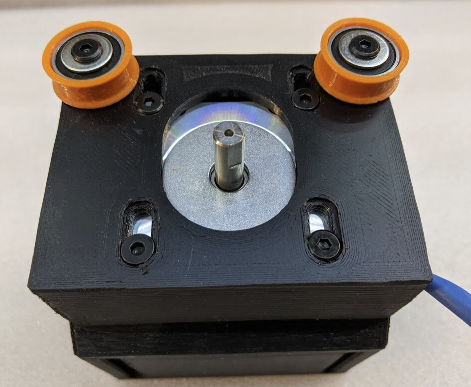
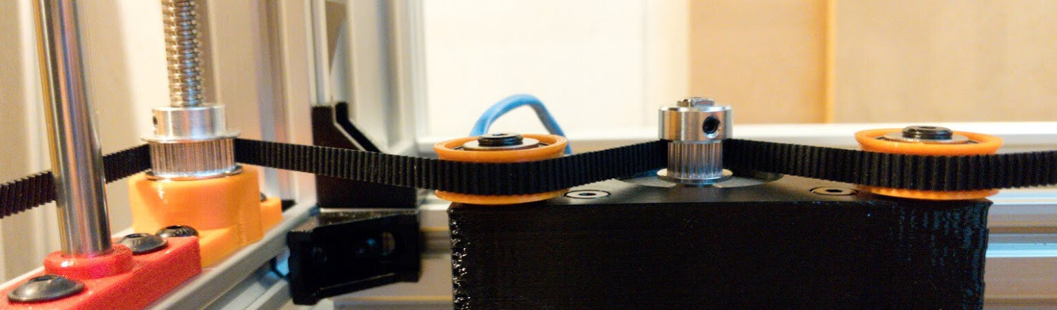
So far, the splice has held, the teeth in the spliced section run fine through the toothed pulleys, and I’ve been able to use the handwheel on the bottom of the stepper to move the Z stage. It’s not hard to move; I have no worries now about it working even if it’s loaded down fairly heavily. I haven’t even greased the lead screws yet.

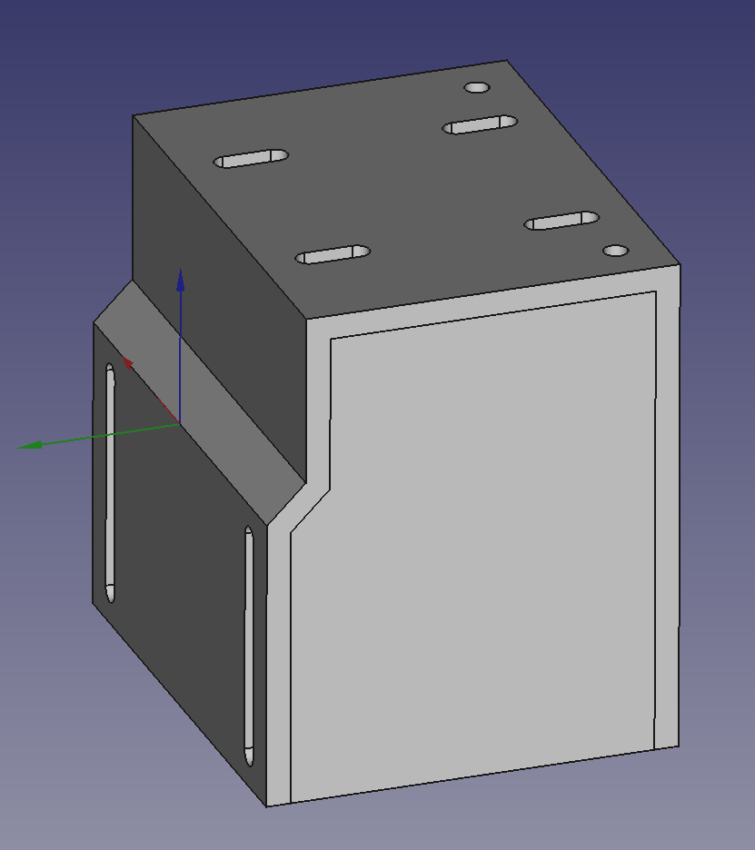
I think that if I do this again, I’ll probably get better at lining it up, but this isn’t too bad. I think it might make sense to design yet another 3D printed part as a jig, though I would still use a section of belt to align the teeth. If anyone else ever actually makes another one of these, it would probably be worth the time to design a jig. It would sure be a lot easier to splice it in place on the laser with a jig, and it would probably be a higher-quality splice. This splice is functional but not beautiful.

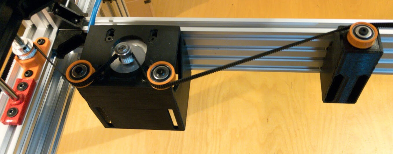
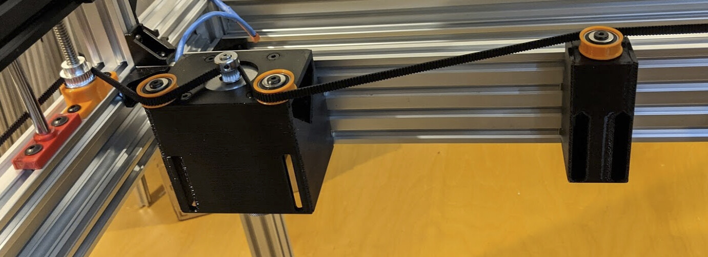
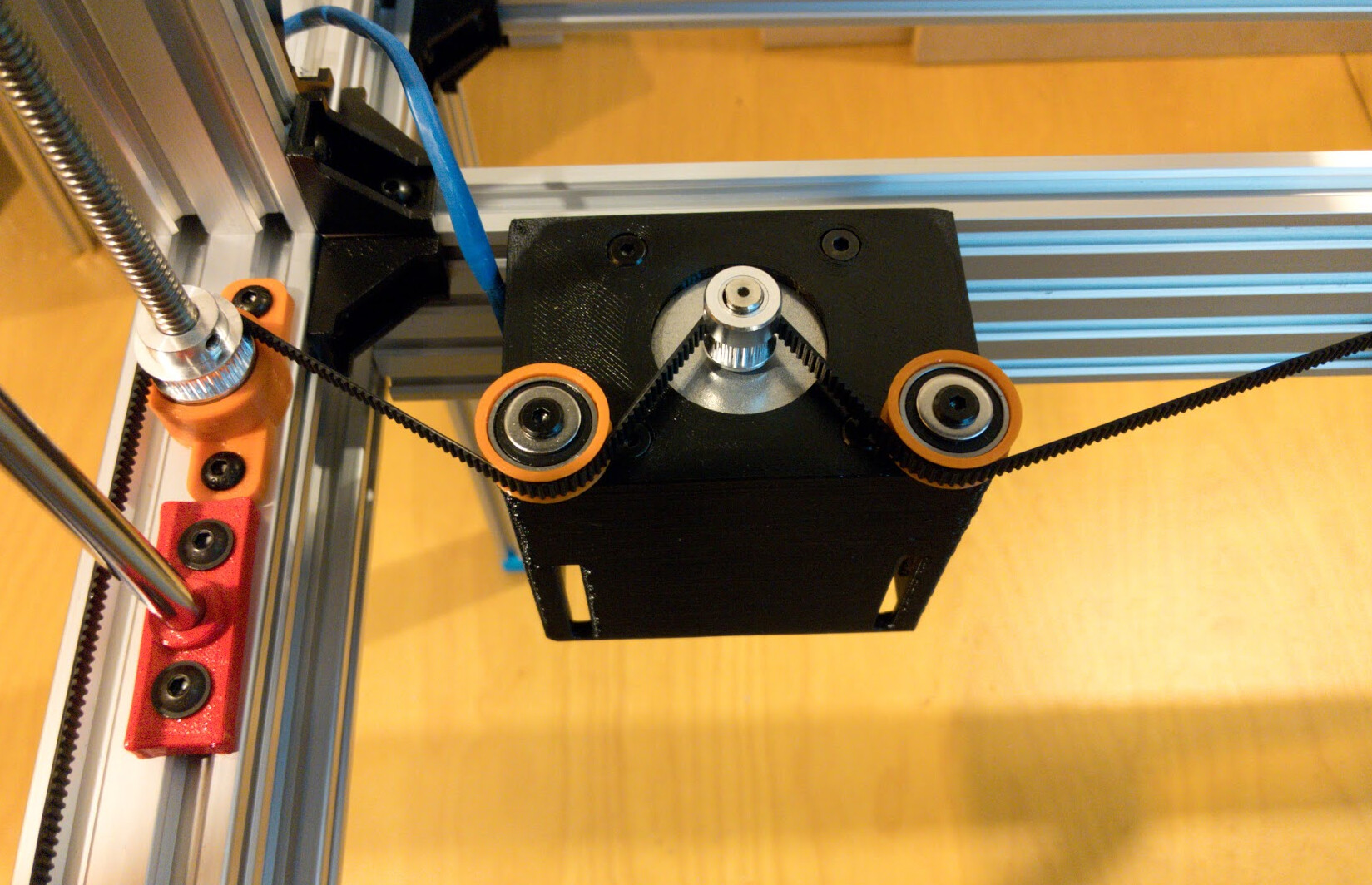
Installed, this looks a lot the same as earlier pictures, but this time I have used the belt to raise the bed about as high as I’m ever likely to want it; it’s pretty close to the nozzle here. You can’t tell that — except that before the bed would have been very visible from this angle.

I think that’s enough work on Z now that I’ve recovered, I think, from the suspended Z idea. Now I just have to decide what’s next and get started on that!

2 Likes

With the honeycomb bed in place, the Z stage is too heavy for the belt. The GT2 belt is skipping steps at the stepper pulley. I may need to upgrade to 3mm or 5mm pitch belt, or change to larger pulleys on the trapezoidal rod, and might have to change the stepper mounting box to move the idlers closer together to get more teeth engaged on the stepper pulley. But also I’m worried that the NEMA23 stepper motor won’t be strong enough to move the bed even with larger pulleys on the threaded rod (still fitting within the outside panels that aren’t installed yet) so I might need to switch to a gearhead stepper too.

Since I’m planning to cut flat stock first and I can adjust the focus with the adjustable nozzle, I can fix this later.

2 Likes

I looked at 3mm and 5mm pitch belts. I ended up deciding that if it’s skipping now, I need to substantially beef it up, so:

  • 5mm pitch (HTD5M profile)
  • 15mm wide belt (neoprene and fiberglass since I now know a good way to bond it)
  • Two-stage drive. Probably 14 tooth on motor driving 30 tooth idler connected to another 14 tooth driving 30 tooth on the four lead screws. 30 teeth is about 25mm radius which will fit inside the case but not much. I’ll plan to move the motor to the electronics bay and run the loop through a slot in the rear of the laser enclosure; this will keep the belt out of the laser path entirely.

I don’t expect to have much free time in the near future to build it, but then it will take a while for my aliexpress order to arrive anyway, so I placed the order. Adding about $100 to the BOM for pulleys and belt. I’m ordering 10 meters of belt in case I screw one up, or to have a spare on hand for when the first belt dies; either way… I also ordered a closed belt for the first stage reduction. Z won’t move fast, but now I can be confident it will move. :relaxed:

2 Likes