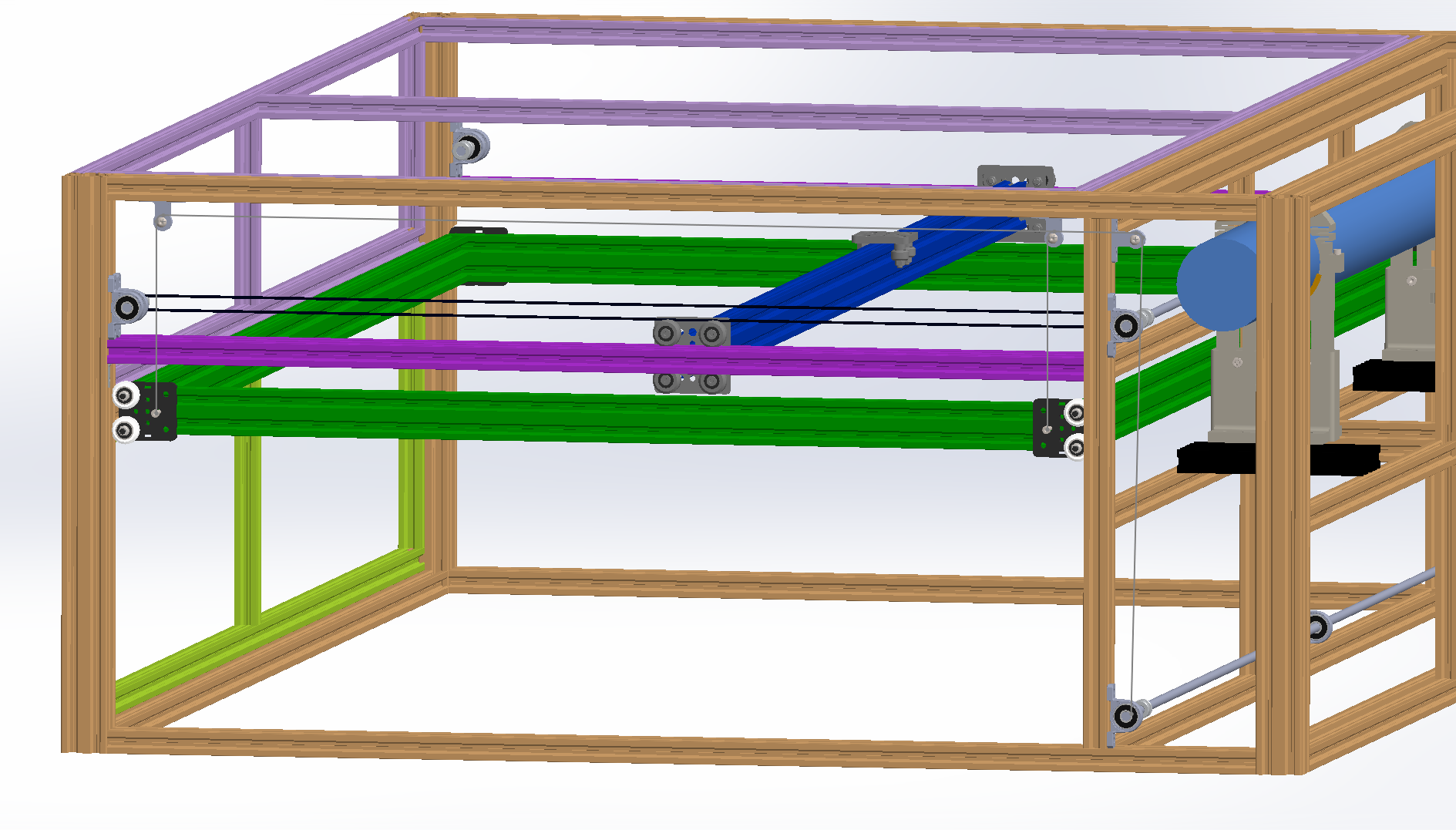
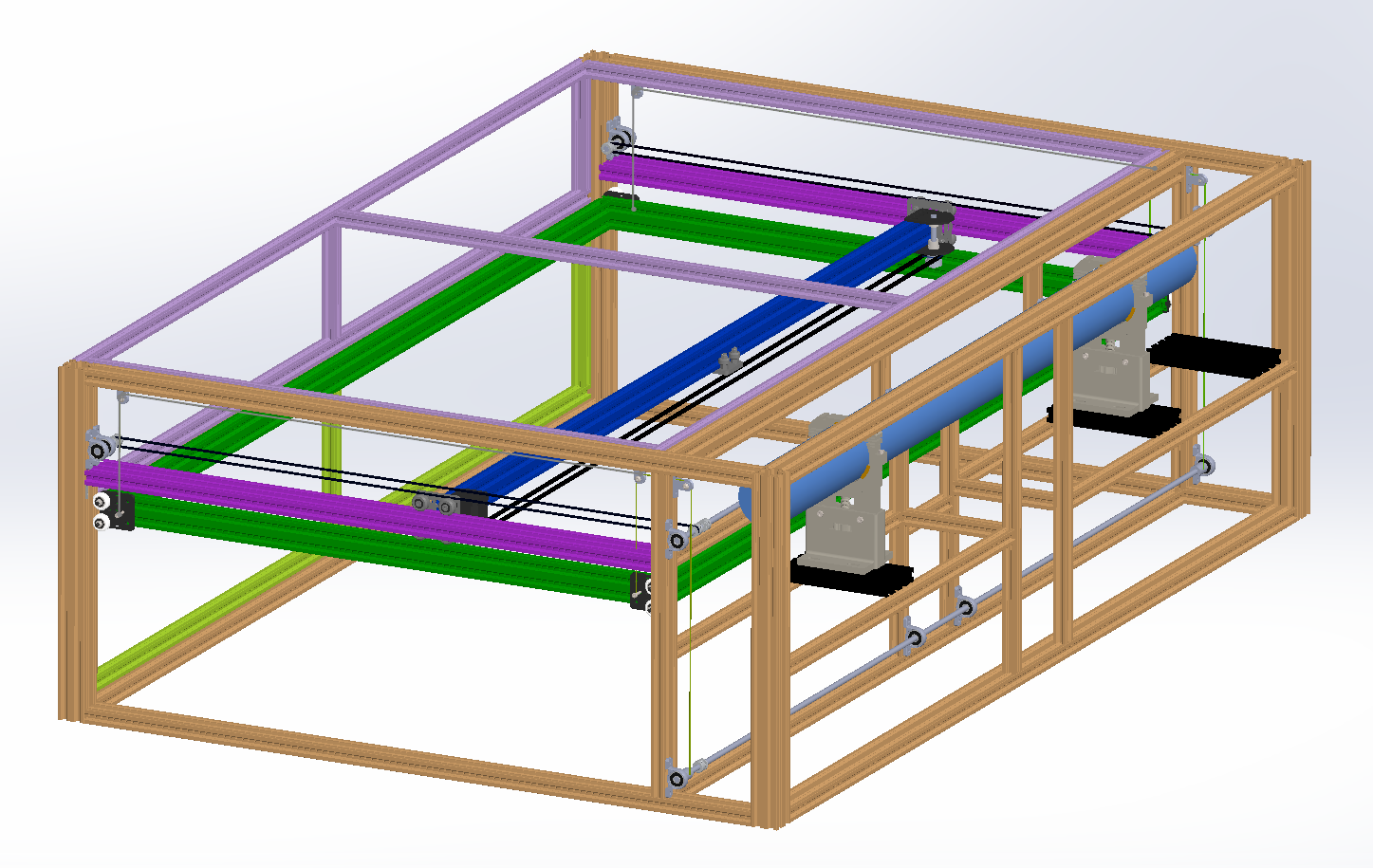
This shows a randomly-colored frame with the basics of the design, looking from slightly to the rear of the right side of the unit, since that gives the best view of the belt paths, I think.
I’m modeling the right side, and not worrying right now about equivalent work on the left side. I’m just trying to prove the concept here. Imagine equivalent belts run on the left side as well.
The black belt from front to back, the Y belt, is intended to be an open belt that is clamped in a belt block to the gantry plate at the end of the (dark blue) X gantry beam.
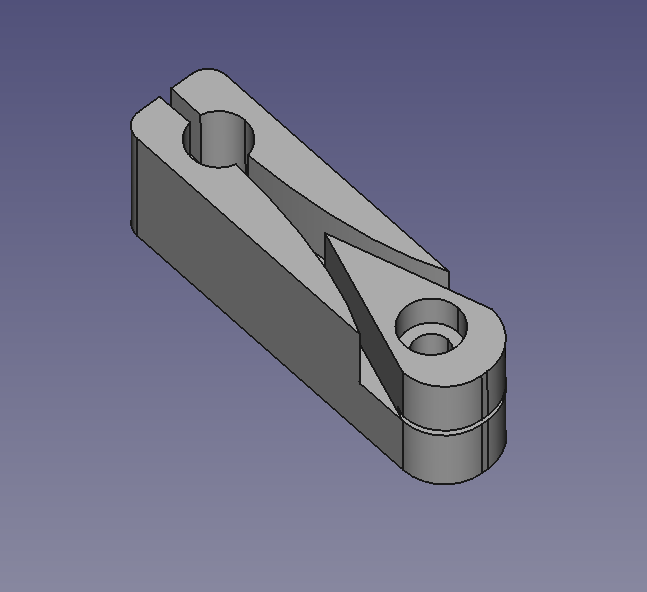
The thin gray lines from the gantry plates on the (green) bed frame go over pulleys hanging from the top of the frame, then over a pulley in the back, and down to a rod that here is modeled at the very bottom but is likely to be right below the laser shelf instead; I’m still playing with that. Those lines are intended to be 100lb test spectra. The bed is attached to four gantry plates, one at each corner, each of which has two wheels which ride in v-slots in the frame. Really for exact constraint it should be just one wheel at each corner. I don’t have a good reason for two beyond redundancy and ease of assembly (it will be easier to line the gantry plate up in the bed slots this way, I think). The lines will go through holes drilled in the (fuschia) Y rails, but those are 2060 and the lines won’t interfere with the wheels on the gantry plates for the X (dark blue) gantry.
I haven’t modeled running the X axis just yet; I’m still deciding whether to use the gantry plate or just buy a 1500mm chiwin rail. Robotdigg has 1500mm MGN20 for $90. But I have the gantry plate already, so I might start there. I might end up mounting it underneath so that I can run drag chain right on top of the gantry for carrying air assist.
The blue cylinder is a bounding cylinder around the 80mm laser tube.
The torsion rods are 8mm, run through four KP08 self-aligning bearing blocks. They aren’t really 1500mm long; they are really two rods joined with diaphragm couplers that I didn’t model. But with the four bearings spread out, I don’t forsee any problems with the torsion rods whipping; neither is going to turn fast.
I haven’t modeled any of the electronics, drag chain, or optics components. I have set bounds in the model to match the dimensions of the laser optics set I think I want to use, but for which I don’t have a model right now. There’s enough room that the optics set dimensions aren’t critical.
The model is terrible. I’ll share the solidworks 2019 files with anyone who seriously wants to play with this design, but ultimately if I make this my current plan is to convince myself that it will all fit together, order all the parts, and then re-do the model from scratch with a better understanding of how it will all fit together in the end.