One thing to consider is pully placement if you are going to have a pass through. Also specs for sizing cables for maximum weight bearing.
Thanks!
I’m not intending passing through the back, but the lime green in front is a lower door intended for pass-in. The belts are entirely out of the way of that, on purpose. I’m hoping that having a large cutting area reduces utility of pass-through. I’m trading that off for cutting width. There will be a wall behind it anyway. 
The four suspension cords I have in mind are 100lb test braided spectra fishing line, and I could easily double them for a total of 800lb test. 3/32" / ~2.5mm polyester sheath spectra leech line has a safe working load of 380 lbs / 170 kg (nearly a ton ultimate tensile strength). Similar for unsheathed 7/64" braided spectra (e.g. amsteel), but braided has a little more stretch, and the stretch increases a bit with diameter. So not much stretch in braided fishing line, but it might be meaningful in the 7/64" which would probably be gross overkill. With the 5mm v-groove pulleys I don’t think I want to use 2.5mm line because it might bind in the pulleys that have to take two lines.
Even if I mount a rotary axis on the bed, it’s not going to be remotely heavy enough to matter.
2 Likes
I mirrored parts to the left side and added X hardware. I haven’t worried about belt clamps; that’s trivial to print or mill from aluminum.
I was going to show a more conventional view, but it turns out that the right rear quartering view shows the belts and rods better than, say the typical trimetric view. So here it goes again:
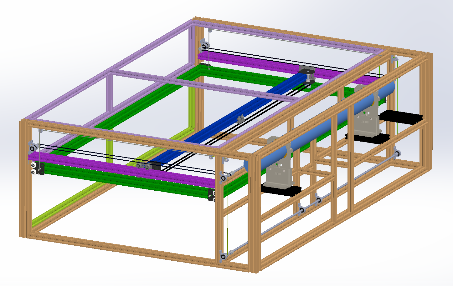
No banana for scale, but inside the 4040 corner columns are 1 meter pieces front-to-back and 1.5 meter pieces side-to-side, so lots of room for a true 80W tube.
I can make a STEP if anyone wants to look around in the model; let me know.
1 Like
Yesterday, I started milling brackets for the v-groove bearings from 6061 aluminum, and made a small mistake. Reviewing the partially-completed work, I decided to change the design of the brackets to improve design for manufacture. In changing the design, I realized that the new design might work in plastic, so I made further changes to make it print better.
Last night, I printed a few test articles in PETG, with the idea that I could test strength, and at worst would have a model to keep handy to help avoid stupid mistakes while milling the new design in aluminum. This morning, I set up a test article to check strength. I maxed out my hang scale at 110 lbs / 53.75 kg without any obvious deformation or noises. In fact, I hope I didn’t damage the scale because I think I momentarily hung all 160 lbs of me. I damaged screw threads on the screw I was using for the axle but the plastic bracket was completely undamaged. So I think I have a successful design in plastic.
4 Likes
The cheapest vgroove bearings are 3mm bore or 8mm bore. I don’t really want to hang a 1475mm x 850mm bed from 4 3mm bolts, but 8mm feels like overkill. Yet $3/each is the lowest price I have found for 5mm bore, 22mm diameter, 5mm thick v-groove bearings, in 5 packs when I need 6 so of course I have to buy two, and it’s still cheaper than any other source of 5x22x5 v-groove bearings I have found.
I found that they are 625ZZ 5x16x5mm bearings with a 3mm larger outside radius with a v-groove cut in it. This gave me the idea that 605ZZ 5x14x5 bearings are a cheaply-available common size, so I could make v-groove sleeves for 605ZZ bearings on the lathe. (Mark Rehorst said that using spectra on printed idlers on his sand table damaged printed pulleys, I think.)
Or I could spend the extra $22 on just buy the right pulleys and have 4 left over. 
They aren’t high-quality pulleys, but I’m not going to run them fast or far, so I don’t care if they make a little noise.
2 Likes
I went with the real v-groove bearings.
I discovered that I have only 2 mini gantry plates and started to re-think whether I need gantry plates to hold the wheels for the bed, and I think I don’t.
The plates served two purposes: holding an eccentric nut to adjust the wheel engagement, and attaching the spectra line for Z bed suspension.
I realized that if I put the Y-oriented bed sides inside the X-oriented bed sides, I can put the wheels on screws tapped into the X-oriented extrusion, and then adjust wheel engagement by locking the Y-oriented bed sides inside with some preload applied. Then I can 3d print a separate block to hold the suspension line.
For the wheels, I’ll use a long full-thread M5 screw, and lock the wheel to the head of the screw with a nyloc nut. Then I’ll put a standard nut on the screw, thread it into the extrusion, and use the standard nut to lock the wheel at the right length to engage the V-slot.
I’m also going to use 2060 instead of 2040 for the bed frame, now that I bought a 900x600 honeycomb bed to hang inside for most work. Anything that needs to use the full size I can figure out workholding more or less like I do for milling weird-shaped objects: find a way to make it work. ![]()
I’m going to swap sides; HV will go directly under the anode and I’ll end up with very short HV line. I’ll put the low-voltage parts on the left. I still plan the control wart on the right, but will have to work out signal wire routing and I recognize it might not work out. I’m still thinking about this. But the shorter the HV wire, the happier I’ll be.
I’m thinking of remoting the air pump due to vibrations. It has shock mounts, but I think I’d see surface imperfections on cuts if I mount it inside the case. That would also possibly make it easier to add a valve and flow meter.
I’m 98.75% sure I won’t need a tube wart on the right side for the 100W tube. If I have modeled this correctly, I’ll have at least 30mm between the anode end of the tube and the aluminum-sheathed and grounded side. There won’t be lots of room between the cathode and the first mirror, but content here that I rescued from Google+ tells me that’s OK. ![]()
1 Like
I used the realthunder branch of FreeCAD to design 3D-printed blocks that screw to the sides of the bed with t-nuts and hold the spectra suspension line. The line runs around a groove that holds it in place, and then it is guided to the top where there is a slot. The idea is to use a double length of suspension line, running the middle around the groove, and attaching both of the tree ends to the winding pulley.
The line also runs around the lower attachment screw so it’s not just plastic holding it up here—though on the other side, it is just plastic holding up the v-groove bearings, and they were clearly strong enough.
I plan to print in PETG, 100% infill, all perimeters.
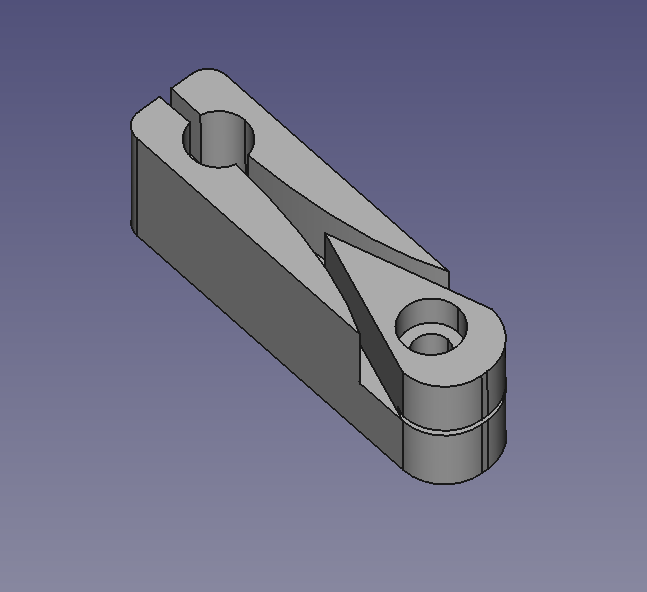
FreeCAD model, STL, and 3mf file are available at GitLab.
2 Likes
I discovered that the brackets I made were dimensioned for 16mm bearings instead of the 22mm bearings I eventually got, so I have to start over with printing. It will take over 6 hours to print six bearing brackets and four suspension blocks. Good thing I have a full task list today to keep me busy while my printer is patiently printing plastic!
3 Likes
My son has convinced me to switch from wheels to linear bearing blocks. I have some with IGUS bearings in them from early (and failed) attempts to improve print quality on my now-dismantled first 3D printer, and also from that printer I have some more 8mm rods that are long enough. I just need to design something to use to attach the bearing blocks to the bed. So more quality time in FreeCAD I guess!
I wish there were a KFL08 variant designed for the 20mm pitch rails, then I could just order it. But KFL08 would interfere either with the outside panels or the linear rail carriage depending on how I mount it, so I just have to machine or 3D print something instead. Since the rods don’t have to turn, drilling 5.5mm, 8mm, and 5.5mm holes in a line in a piece of aluminum scrap 8 times should do the trick.
Then I’ll find out whether the rods are hardened or just chromed, depending on how hard they are to cut. But I have an angle grinder, so nothing will stop me! 
3 Likes
I don’t have a set of reamers, so I tried plunge milling with an 8mm endmill, but that wasn’t a tight enough fit to keep the rods steady. Also, the ⅛" aluminum I found was low-quality gummy junk that smeared all over the endmill.
New plan is to 3d print in plastic and drill up to 5/16, 0.06mm undersize.
I could use M3x25 screws through two holes in the SC8UU blocks to hold them to drop-in t-nuts in the bed. I don’t have M3 slide-in t-nuts handy and while I’ve made my own slide-in t-nuts on the mill before, that’s further down the rabbit hole than I feel like going today. I think that will solve the X/Y constraint problem well enough. There aren’t going to be a lot of side forces, it just needs to not wiggle. 
3 Likes
Drilling out 5/16 was perfect for a very tight fit. The 8mm rods are a little bit undersized. I realized that just like the linear bearings, the IGUS bushings rattled a bit in the bearing blocks. I shimmed out most of the play with pieces of soda can halfway around the IGUS bushings inside the blocks. I had to use two .5 mm thick washers to use M3x25 screws through the blocks to have the right clearance in the extrusion channel.
The rods were indeed through-hardened. I tried parting them off and that only demonstrated they hardened steel is hard. So I set a rubber blanket across the ways and used a cut-off wheel to cut the rods about 2mm oversize while running the lathe at its slowest speed, and then finished them to size on the bench grinder. Afterwards I cleaned the ways of any spare grit that the rubber blanket didn’t catch.
3 Likes
Here’s a sadly blurry picture showing the SC8UU blocks, printed end fix blocks, and suspension blocks as attached.
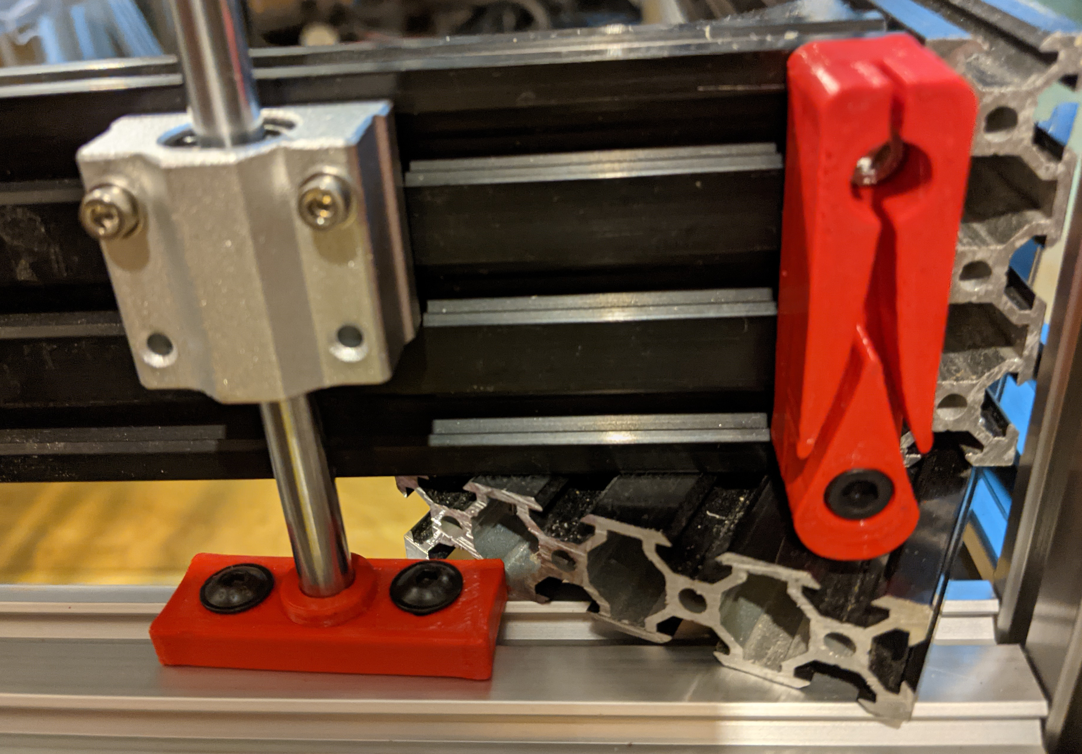
Note that the holes in the SC8UU blocks aren’t on a 20mm pitch so I can only use two of the holes to attach it to the bed frame. That’s OK.
Installing those rods which I had ground to length within 0.5mm (and probably better) made it clear that one of the corners had slipped down about 4mm in all the disassembly and reassembly I had to do, so I fixed that too.
3 Likes
I finally realized that this configuration interferes with where I had expected to run the drag chain. So now I’m playing with new ideas on that. As a result, I discovered that you can get 7mm x 7mm drag chain, and I think it will fit where I need it. 
2 Likes
My next task has been to find a way to attach the UHMWPE string to the Z torsion rod.
It’s harder than it seems.
I made plastic clamps to hold the string against the rod and with 15mm of tightly clamped plastic, it slipped with 30 lbs of force; even with 50mm of very tightly clamped plastic, it still slips at around 70 lbs of force. Then I tried installing it, and even with the clamp forced open I can’t get it installed on the torsion rod because it’s too tight. PE is almost as slippery as PTFE (“poor man’s teflon”) and UWMWPE though much stronger than steel and much less stretchy is very slippery and hard to fix in place.
So now I am starting over on a new design. This is one of the trickiest design challenges I’ve come up against so far, and I thought it was going to be fairly easy. 
2 Likes
Everything is a journey, nice you are keeping up this diary. Ive not gone with a laser as far as you have, but you will definitely help others.
Keep up the good work - its hard enough making your own thing, let alone the documentation you are putting into it. Fair play.
2 Likes
You are definitely further with a laser than I am, since you actually own a working laser cutter. I just have parts and ideas that I sure hope are going to become a working laser soon!
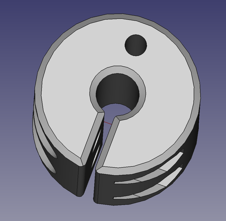
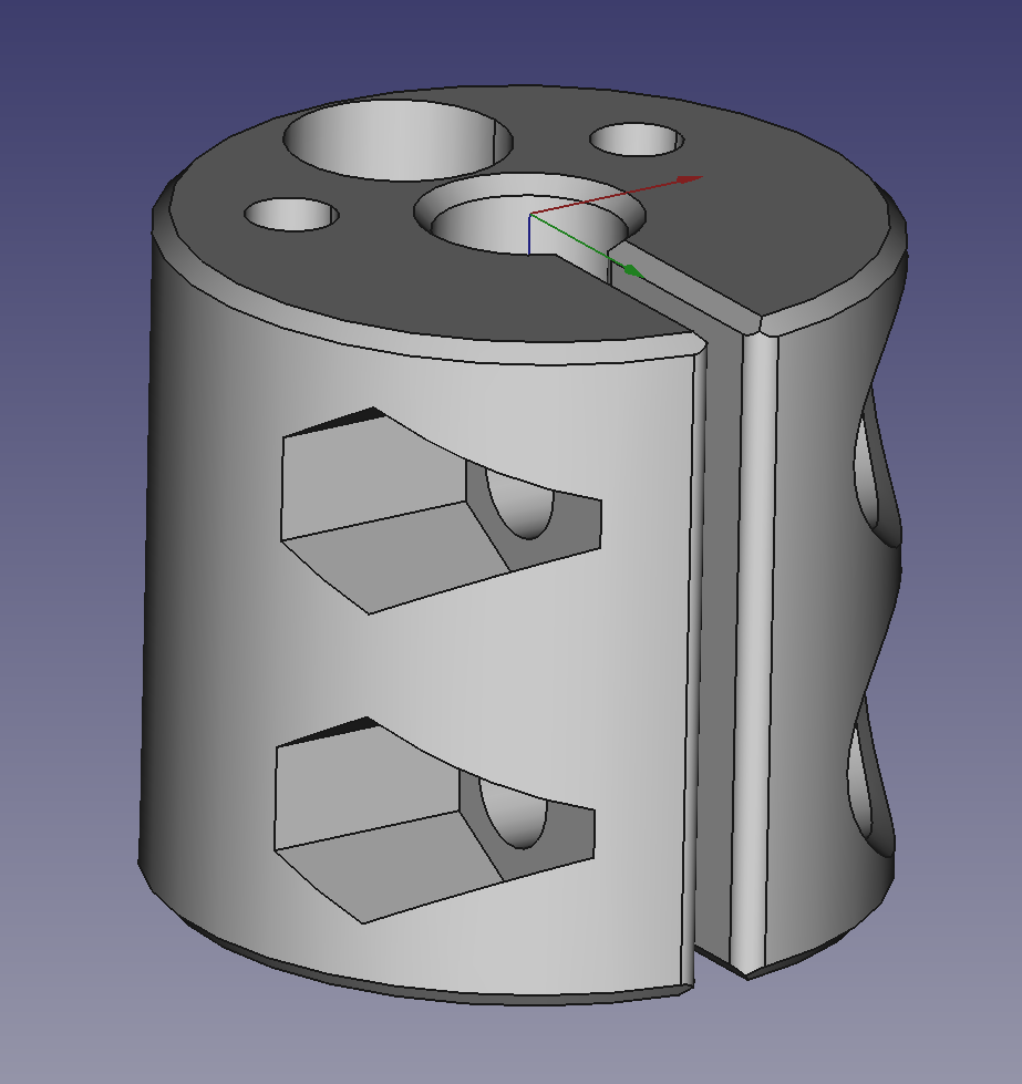
I’ve switched from M3 to M5 hardware, and I added a hole for an M5 bolt through the body to act kind of like a “dog” — I plan to run the cords through the split and then lock two nuts together around the cords on the far side of the split, and use that to fix the cords to the shaft so that as it turns it lifts the whole bed level.
Imagine two M5 flat-head screws in these two holes in the side:
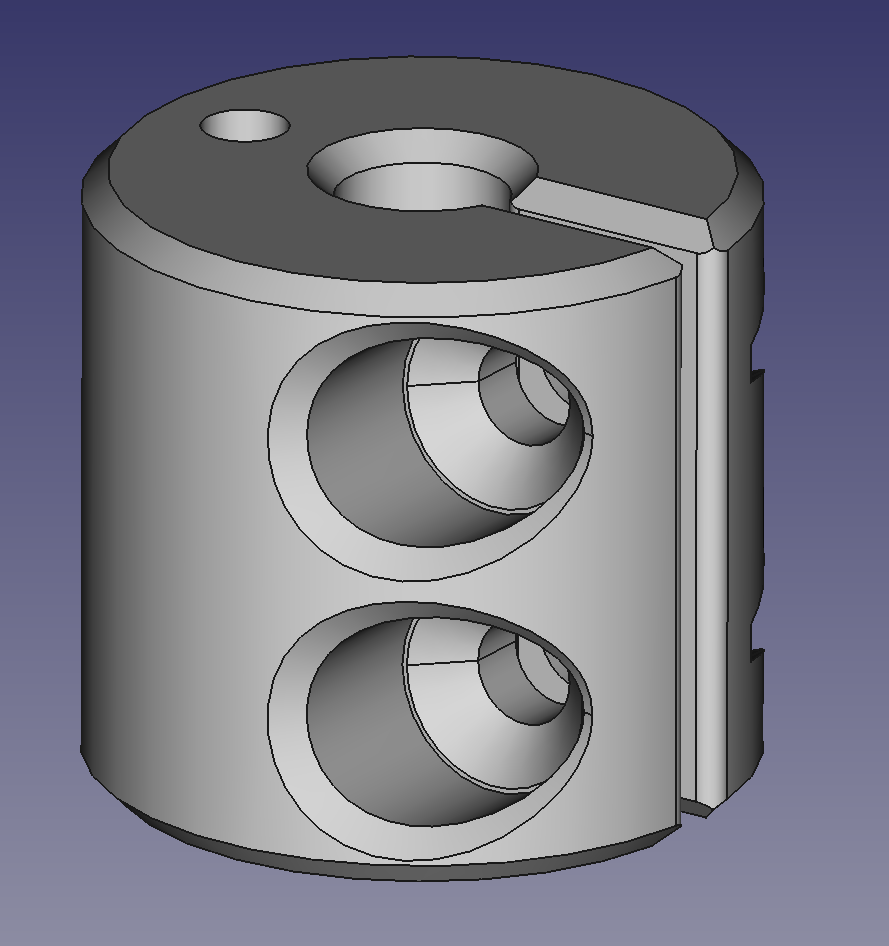
…screwed into M5 nylock nuts on the other side, with printed hex sides that act as a wrench:
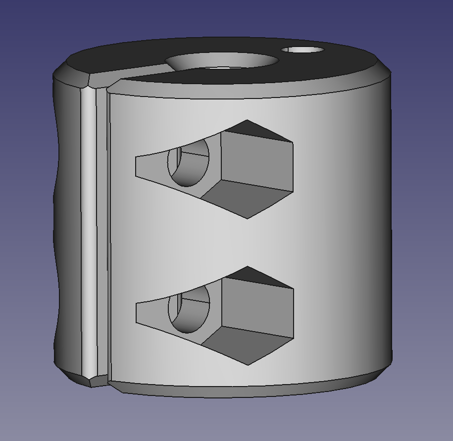
(Yes, the outside is really narrower; that’s to aid in disassembly if necessary.)
The hole in the top is tapped M5 and a 40mm M5 socket-head screw goes through it. Two washers (including a lock washer on the outside, I think) lock around the UHMWPE cord:
Anyway, that’s printing now; hopefully I find this evening that it works.
2 Likes
The first one took 1.5 hours to print. The move from M3 to M5 hardware created larger unsupported overhangs that printed worse, but sere still good enough to use.
The main difficulty I had was that the hole down the side is 30mm tall, and I don’t have an M5 tap with quite 30mm of cutting area. I ended up just pushing a few threads out of the way at one end to have threads all the way through, and it worked fine. PETG is a bit of a pain to tap. It really gums up in the flutes, and even with spiral flute taps I can only tap about 5–10mm at a time without clogging the flutes and having to back out and re-cut.
I haven’t tried a strength test. It looks good enough to print a second. At this point I plan to just install them both and test them.
The UHMWPE I’m using is impregnated with graphite, which is great for being slippery and even more self-lubricating, but also is… great at being extra slippery and hard to fix to the rod! Also the graphite gets all over my hands while I’m working with it.
The v bearings I bought are at best just barely big enough for the four strands (it’s doubled) that have to run through them. While I’m trying to make this work, I’m not sure I’d recommend it to the next person. I think it would have been smarter to use a couple of stepper motors to drive M8*2 lead screw, one motor at each end, and just have sensors/stops to tram them to deal with them getting slightly out of sync. At this point, there’s nothing actually preventing me from switching except curiosity as to whether this approach will work.
I note that my solution for the problem of terrible KP08 bearings would generalize to holding lead screws on the sides near the corners of the frame of the bed. So if this suspension approach ultimately fails, I’ll have some unused 8mm rod and exactly the eight extra 608 bearings I would need to move to a more conventional design.
2 Likes
I printed the second and tried an installation. I was able to lift the bed by turning the torsion rod, but it wasn’t perfectly level, and adjustment was extremely difficult. Part of this was because I had expected to be able to adjust it with the cord pulled through the slot underneath the clamp-closing screws, but the cords got a bit pinched between the clamp and the rod and hung up subtly, so one side was under slightly less tension than the other.
The side hex recesses turned out not to be tight enough to hold nylock nuts solidly, so I had to test with regular nuts.
I used an ULP screw head for the dog screw that holds the thread, but it still seemed likely to tangle the cord around the head as it turns.
The next design iteration buries the head of a standard M5 socket head screw to avoid tangling, which also solves my problem with short M5 taps by reducing the length of the tapped segment. I have added a hole for the cords to go through from the head side to the far side, and because I don’t know which side will work better, I added a hole on each side. I left enough plastic to be strong enough not to break. I reduced the nut clearance, hoping that might make it possible to use nylock nuts, but I don’t think it will matter in the end.
Ultimately, even if this works, I expect that it will be less accurate than stacked belts, so for anyone following along, I’d recommend single-start trapezoidal lead screws.
3 Likes
My thought would have some sort of turnbuckle for leveling and just tie the line to the buckle with a fisherman’s knot?
I haven’t figured out a way that any form of turnbuckle could fit…
This is whipping around inches from the laser tube, so anything that might come loose and hit it would be an expensive mistake. Especially since I went all out and bought a Reci…
3 Likes