Single-cell 18650 Lipo Charger for use with my various projects

Single Cell Lipo Charger

This single cell lipo charger was created to solve a problem I encountered during a recent project. I constantly needed to recharge 18650 cells, and while I could also use my 4-cell charger, that didn’t always turn out to be the most practical. I also intend to use this small charger as a building block for a future complete power solution, including a boost converter, more protection features and proper cell status indication…

I am currently moving towards building more projects that will be used outside, “in the wild” and thus need a reliable way to power those. True to my way of doing things, I want to build my own stuff as far as possible. That way, I learn more about the technology, and I am sure that everything meets my exact specifications.

What is on the PCB?

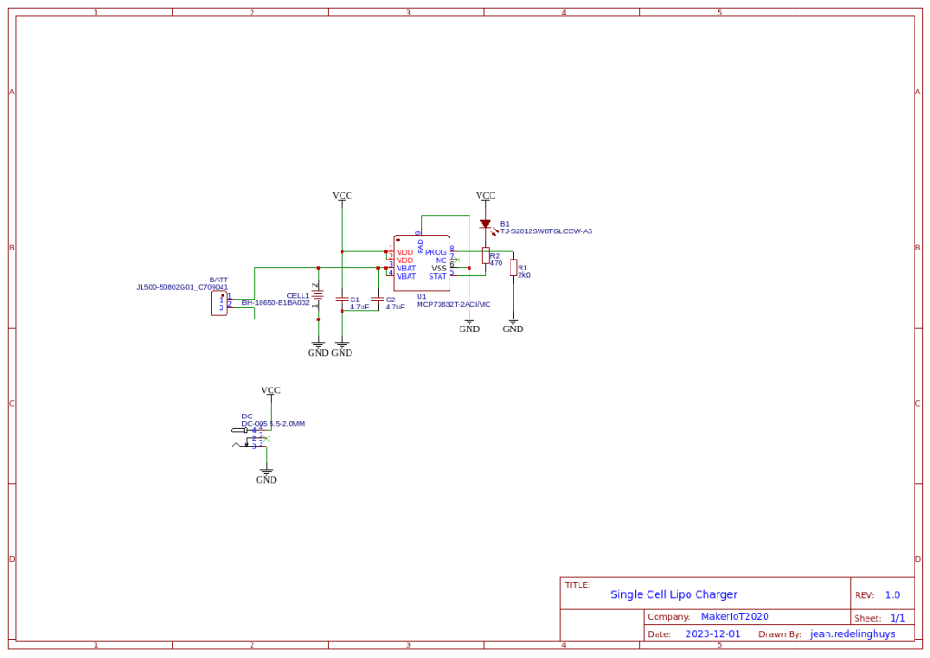
The charger is based on the MCP73832T, by Microchip, which contains quite a lot of useful features, in a small package as well at a relatively small price tag, and with very few other required supporting components.

  • Linear Charge Management Controller:
  • Integrated Pass Transistor
  • Integrated Current Sense
  • Reverse Discharge Protection
  • High Accuracy Preset Voltage Regulation: + 0.75%
  • Four Voltage Regulation Options:
  • 4.20V, 4.35V, 4.40V, 4.50V
  • Programmable Charge Current: 15 mA to 500 mA
  • Selectable Preconditioning:
  • 10%, 20%, 40%, or Disable
  • Selectable End-of-Charge Control:
  • 5%, 7.5%, 10%, or 20%
  • Charge Status Output
  • Tri-State Output – MCP73831
  • Open-Drain Output – MCP73832
  • Automatic Power-Down
  • Thermal Regulation
  • Temperature Range: -40°C to +85°C
  • Packaging:
  • 8-Lead, 2 mm x 3 mm DFN
  • 5-Lead, SOT-23

A proper screw-type connection terminal on the output, as well as a DC Barrel Jack on the input, completes the PCB. On future revisions, I will seriously consider having a voltage-limiting circuit on the input side, since the MCP73832T is only capable of accepting an input voltage of up to 5.5v DC.

This is not a problem to me, as I will be using the current version for my own personal use. I do however believe it is essential to ensure that no over-voltage conditions can accidently occur BEFORE I will give this to someone else to use.

The schematic

Manufacturing the PCB

The PCB for this project was sponsored by PCBWay .

Disclaimer:
Clicking on the PCBWay link will take you to the PCBWay website. It will enable you to get a $5.00 USD voucher towards your first PCB order. (Only if you sign up for a free account).

Assembly and Testing

Assembly of this PCB was quite easy, providing that you have a stencil, it will not take you more than a few minutes.

The PCB’s really came out very nicely :slightly_smiling_face:

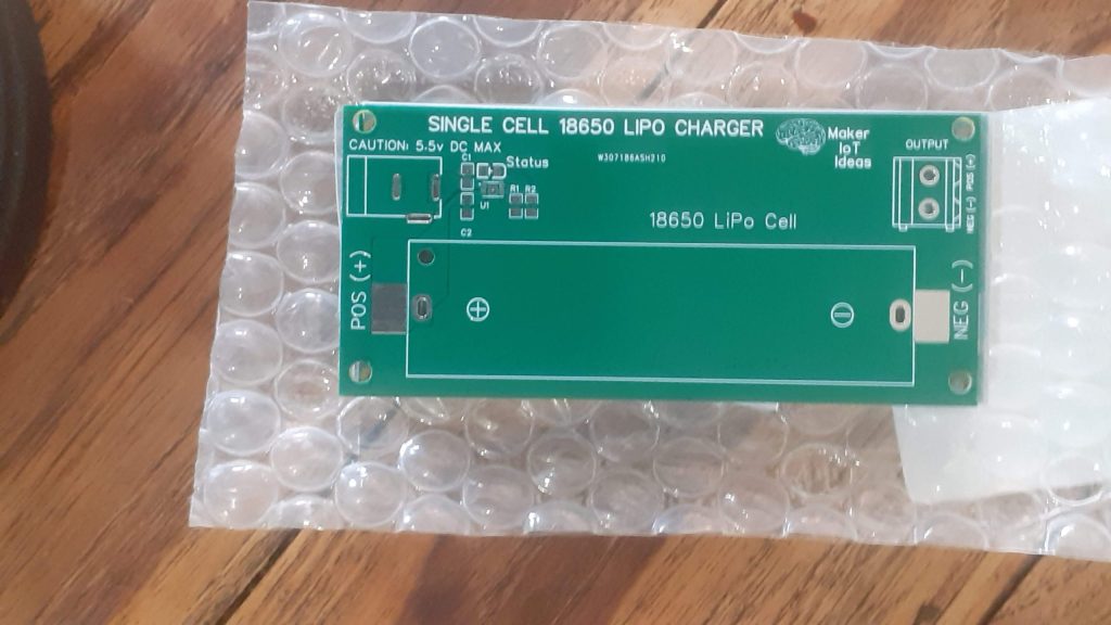
I have also made provision for using a through-hole 18650 battery holder, just in case you are like me, and have a few lying around in a drawer, or could just not be bothered with using the SMD version…

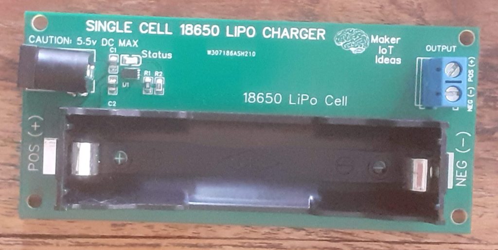
The completed PCB is relatively small and compact, taking into consideration the size of the 18650 cell of course… The screw terminal on the output really helps to keep everything secure when using the module to power a project, and the DC barrel jack provides a good connection to charge it all back up again…
Now, If I just remembered to add some form of voltage limiting on the input, as well as include a boost converter, It would be the perfect little “power bank” project… For now though, let’s leave those features to the future, as this is already extremely useful as is.

1 Like

I have been away for a while, dealing with a broken wrist and all the unpleasantness that goes along with that etc. That is now sort of out of the way, and it is back to work :slight_smile: Definitely long due, as far as I am concerned;;;

1 Like

Here are a couple of useful things to consider adding:

Inputs:

  1. A USB-style input so that those old bricks can be used for charging.
  2. A screw or 2.54 pitch connector so this can be used with a solar panel

Outputs:

  • An optional diode in the output such that these can be ganged
  • When building solar chargers I have found that boost converters need a low voltage shutdown such that when the battery is low the output is shut off. Otherwise, they keep running in the 2V range driving the load nuts.
  • Battery level indicator LED’s

https://amzn.to/3TOFCoj

As an Amazon Affiliate, I earn from qualifying purchases.

1 Like

Hi Don,

Thanks for some great points …
I will try to incorporate them in the next revision.

All your points are in line with what i want to do to it in future anyway,

The USB input… and the optional diode in output, I did not think of those :slight_smile:

Tell me something, since I am not too clued uo on power stuff … how would the “gang” circuit work?..

I can see an immediate use for that, and to be honest, I have been playing with something similar in my head for a while, trying to figure it out…

Regards

This is a project I started and only breadboarded and recently started a pcb design…

warning! not tested.

I have not yet installed the cutoff circuit since the proto is where I found the problem.

Schematic_4 cell solar charger_2023-12-20.pdf (74.9 KB)

1 Like

That looks interesting.

I played around with those charging modules, but was not too impressed, must have gotten a bad batch… that led me down the current rabbit hole with building my own :slight_smile:

I understand now what you mean with the diode on the output… I had something similar in my mind, see you using a schottly diode, thus low diode drop :slight_smile:

I will get playing on my own improvements of the existing device, and see how that goes :slight_smile:

Thanks for sharing those pictures… shows me that my mental idea is in the right direction at least :slight_smile:

I have used schottky diodes for reverse polarity protection, but at least for something battery powered I would consider a so-called “ideal diode” instead. Do you know about them?

1 Like

Funny you mention these.
I just recently was looking at them for a battery charger in an ESP application.

In the case of my solar charger, I had these diodes in the bin :). I also expect 1A from each panel so I was concerned the ideal diodes application was marginal.

I’d highly recommend adding a protection circuit, primarily for the under-voltage lock-out. I never cared too much about the over-current protection but I’ve killed more LiPO/Li-Ion cells than I care to admit by letting them run down. Even circuits that go into low power state on their own do drain the batteries over time. Reality is I just forget about stuff and then discover the dead cell a few months later…

2 Likes

I tend to agree with the recommendation from Don. That seems like an "ideal diode to me as well… only issue could be that it is not a straight forward “diode” in the sense of the word… But, then, that datasheet seems impressive… will have to try them out to really know

Oh yes, that is part of the next build. especially, as I had used a different module before. That touted auto shutdown etc, but would discharge a cell competely overnight even in the “off” state… THat is part of the experiment here, design and build my own “ideal” charger… that would unfortunately include a few different revisions, adding and changing things until it is perfect

It’s a perfectly straightforward circuit that used to be implemented with discrete components for load sharing and polarity protection. It just got packaged up into an IC and given that name because it communicates so readily the idea of unidirectional current flow without a substantial voltage drop (just whatever you get from the RDSon of the internal MOSFET).

1 Like

Agreed Michael, if you put it that way :slight_smile: What I meant was that it is not a “diode” in the traditional sense of the word :slight_smile:

It is definitely a more elegant device and definitely get rid of some of the undesirable characteristics of the traditional diode - mostly the fwd voltage drop issue ( it is still there , but much lower in this case :slight_smile:

I will definitely try to get some of these, as they seem interesting enough to warrant some “playing around with”

Once again thank you to Don for pointing out this particular component…

I have to admit that my “power electronics” knowledge is somewhat limited and also severely rusted, so being made aware of a “new component type” to play with is definitely worth a lot to me :slight_smile:

2 Likes