I don’t know whether that’s actually some imperial pitch, but that’s neither a standard pressure angle nor a standard tooth form so it simply doesn’t matter. Higher pressure angle is stronger (and noisier) but strength is not an issue here.
I think I’ll just make a whole new set, as parametric as I can, and use standard tooth profiles. Might want to test 2 module and 3 module, but 20°PA is pretty well established as normal and I don’t know of a reason to deviate from that.
Very cool and love your FreeCAD skills! I often look at things posted here and ask myself how I could do THAT with the skills I have. I’m not so great yet at FreeCAD so I might have to give this a shot in Inkscape and OpenSCAD for the STL-2-projection then laser cutting out of 3mm plywood… It’s been a while since I used Inkscape to make gears and I’ve not done both inner and outer gear options.
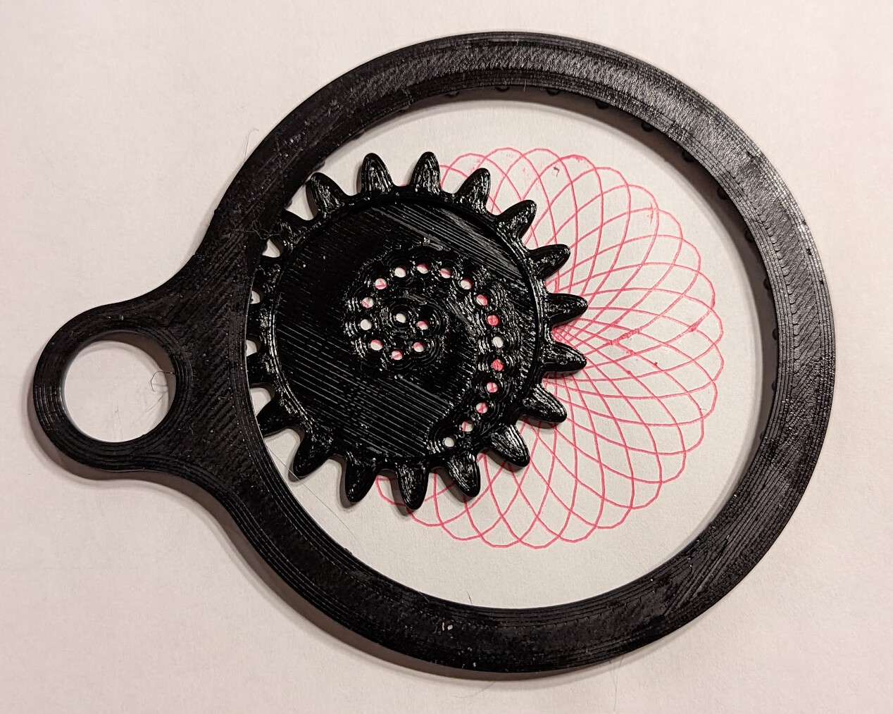
We recently watched an episode of Lost In Oz where a Spirographic gear design was used to show the path of a phenomenon they were trying to predict it’s next location to be.
one of many sites on using Inkscape to make gears:
TIL that Inkscape also has a proper involute gear generator! Very cool!
I don’t see clearance in the Inkscape options. For laser that’s almost certainly OK unless you want negative clearance to account for kerf. But for a 3dprinted internal involute gear I think it’s probably potentially valuable.
I’ve been thinking about my design, and I think it’s actually a 3 module gear with different clearance, tip, and root treatment. I hadn’t played enough with some of the other parameters before I got to my weird not-quite-3-module solution.
Ya, I was pleasantly surprised with how well it makes gears but on doing a quick search on internal involute gears didn’t find much except an unrealistic use of the involute gear to create the ring gear.
I was figuring kerf settings were going to be key to getting reasonably well gears.
And of course OpenSCAD has involute_gears in the MCAD package but I’ve not looked at it closely yet. I’ll pull up your FreeCAD file once I figure out what real options there are with Inkscape and OpenSCAD as I’m far more familiar with both of those than FreeCAD at the moment. Gears are not as trivial as they look.
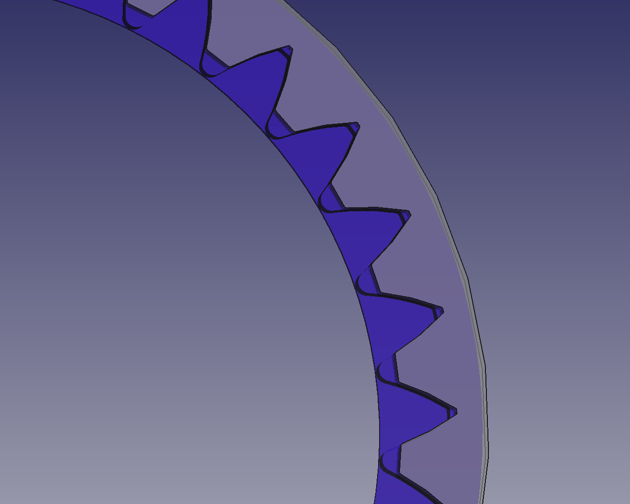
I spent more time than I should have revisiting this. I’ve come very close in form (though not tested a print for compatibility) with these parameters that look very close in FreeCAD:
I’ll share separately when I am satisfied with my parametric model, which I’ve been redesigning repeatedly to react well to choosing different numbers of teeth on both the ring and the gear. It’s getting there!