@aj_laser Please upload an actual SVG file here that is showing the problem. Take a picture of a test cut with from that actual SVG next to a ruler to show the problem.
1 Like
No, you have to have Inkscape set the document size to the size of the object/drawing and I found it helps to make the document just a little larger than the design. I don’t use Standard size documents when importing to Lightburn since really you are importing the drawing, not a large area with lots of white space.
2 Likes
Thanks @mcdanlj & @dougl but I’ll leave out this document size issue for later as my cut sizes are accurate, so I’ll work with this for now.
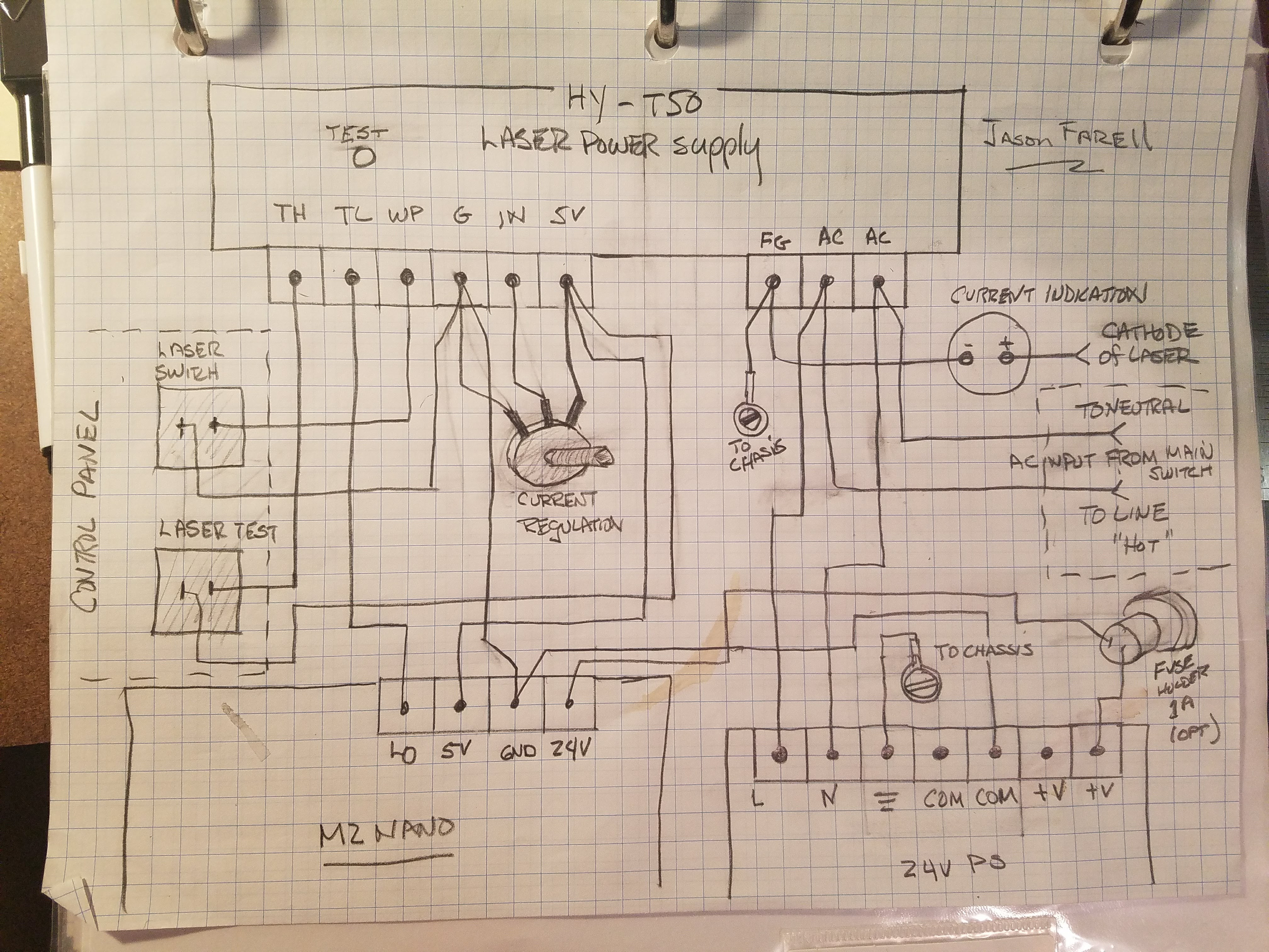
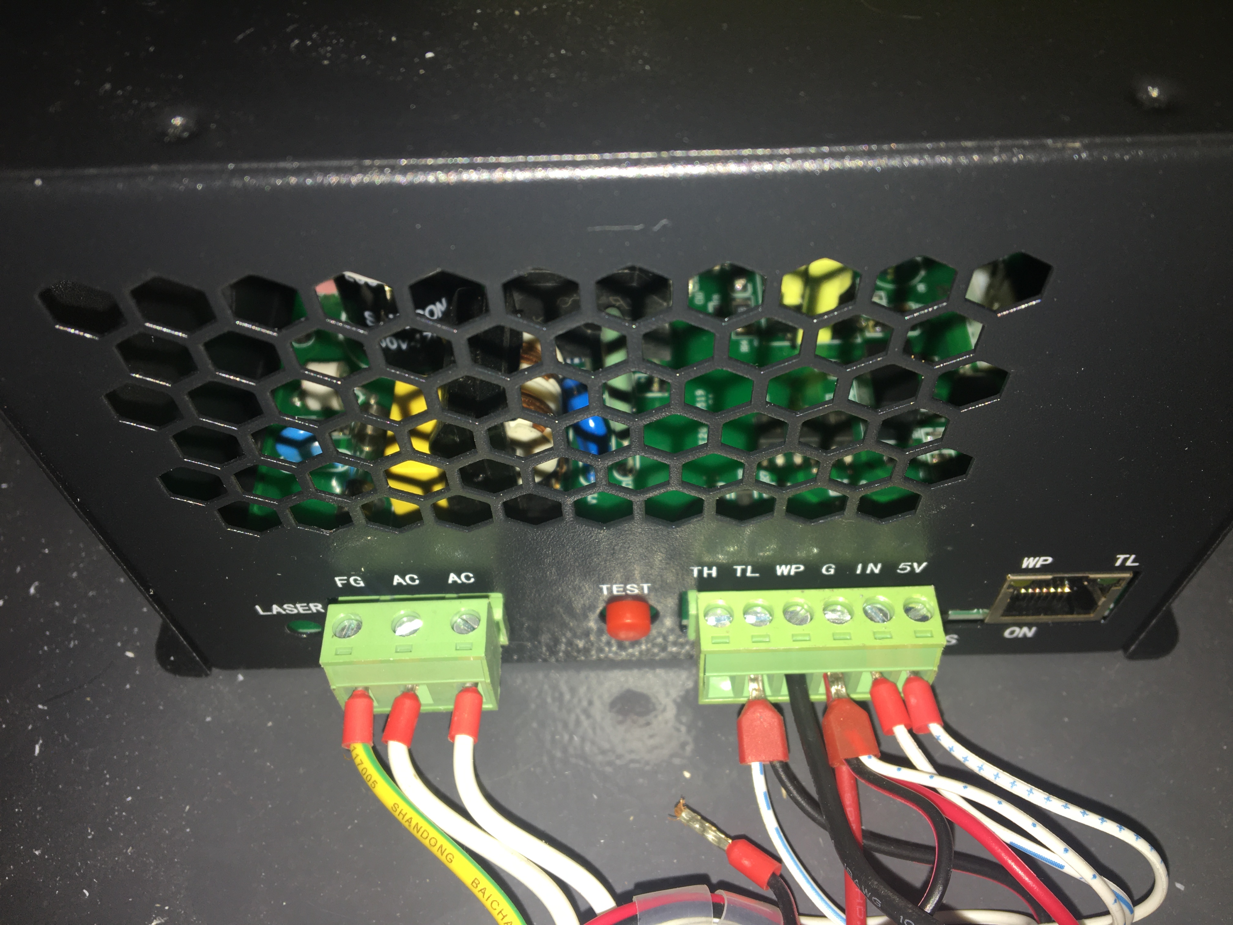
But I have another pressing issue that I’ve encountered, I’m converting my panel to an analog one, but my power supply seems to be different compared to the regular K40’s… so i can’t seem to complete the circuit even with the help of @donkjr 's schematics
I’ve managed to install my mA meter, potentiometer, digital voltage and interlocks and it all works without an issue, but i’m not sure how to install the laser test button
ORIGINAL WIRING
From Main Control Panel (MCP) to LPS:
- K+ —> TL
- K- —> empty
- 5v —> 5v
- IN —> IN
- G —> G
From LPS to 24v board & MCP:
- TH —> empty
- TL —> K+ & 24v board
- WP —> LPS G
- G —> LPS WP, 24v board & MCP G
- IN —> MCP IN
- 5v —> MCP 5v
So with my new panel, I’ve wired it as following:-
NEW UPGRADED WIRING
From LPS to 24v board & MCP:
- TH —> empty
- TL —> K+ & 24v board
- WP —> LPS G & Interlocks
- G —> Potentiometer, Voltmeter, 24v board & Interlocks
- IN —> Potentiometer & Voltmeter
- 5v —> Potentiometer & Voltmeter
I’m not too sure where to wire in the laser test fire button…
hey @donkjr i’ve got a question…
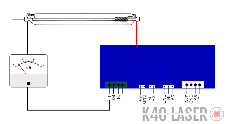
the “current indicator” is that the ammeter or the voltmeter? it goes from the (-) of the laser to ground?
It’s the 30 ma ammeter. It is wired from the cathode of the laser (-) to the meter then the other side of the meter has a wire that goes to the FG pin on the LPS.
What voltmeter are you referring to?
would there be a difference if i place the ammeter between the LPS L & the laser (-)?
ignore the voltmeter, my mistake.
I am confused as to what you are referring to. Where is LPS-L and laser(-)
The milliamp meter is wired in series with cathode and ground. Specifically the FG ground pin on the LPS.
laser cathode ----->+METER------> FG pin on LPS.
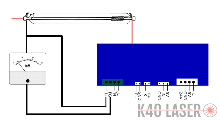
That second way wouldn’t measure current. It’s not obvious to me whether you know this, but in an electrical schematic, wires that merely cross aren’t connected. If they are connected, there will be a dot where they meet to indicate that connection.
I think that Fg should go to chassis ground, and the other wire should be laser cathode to ammeter to L-
@mcdanlj I actually drew the 2nd schematic.
also, that’s why i asked again and drew the schematic because @donkjr said
“laser cathode ----->+METER------> FG pin on LPS.”
so now I’m a bit confused… i know for a fact that if i connect the cathode to the ground (FG) the fuse box in my house is gonna trip…
I understand that. I’m telling you that what you drew won’t work.
The ammeter is between the cathode of the laser and the ground. Not all LPSs have an L- and the example he gives doesn’t have one; it uses FG for L-. I expect that L- and FG are connected internally on your unit but don’t know this; you can test easily with your multimeter…
You know this because you have tried it? Is it a GFCI or AFCI circuit breaker?
Here in malaysia we use a ELCB / RCB / RCCB system
Yes, ELCB == GFCI
First off the LPS in the pictures you provided above has 3 wires, not 4.
It does not have an L-???
That is why I connected the low side of the meter to FG [frame ground].
HUH! In the latest drawing that is a different supply than your pictures above show. What did I miss?
Even if you had a L- on your LPS your diagram that shows one side of the meter connected to L- and the other to FG is shorting out the meter.
On machines that have it, L- and FG are connected together inside the supply.
Please be clear on what connections your lPS has???
If this is true then there is something seriously wrong with this machine’s grounding.
I have a blue wire coming out of the back of my LPS that goes to the cathode and a red one that goes to anode
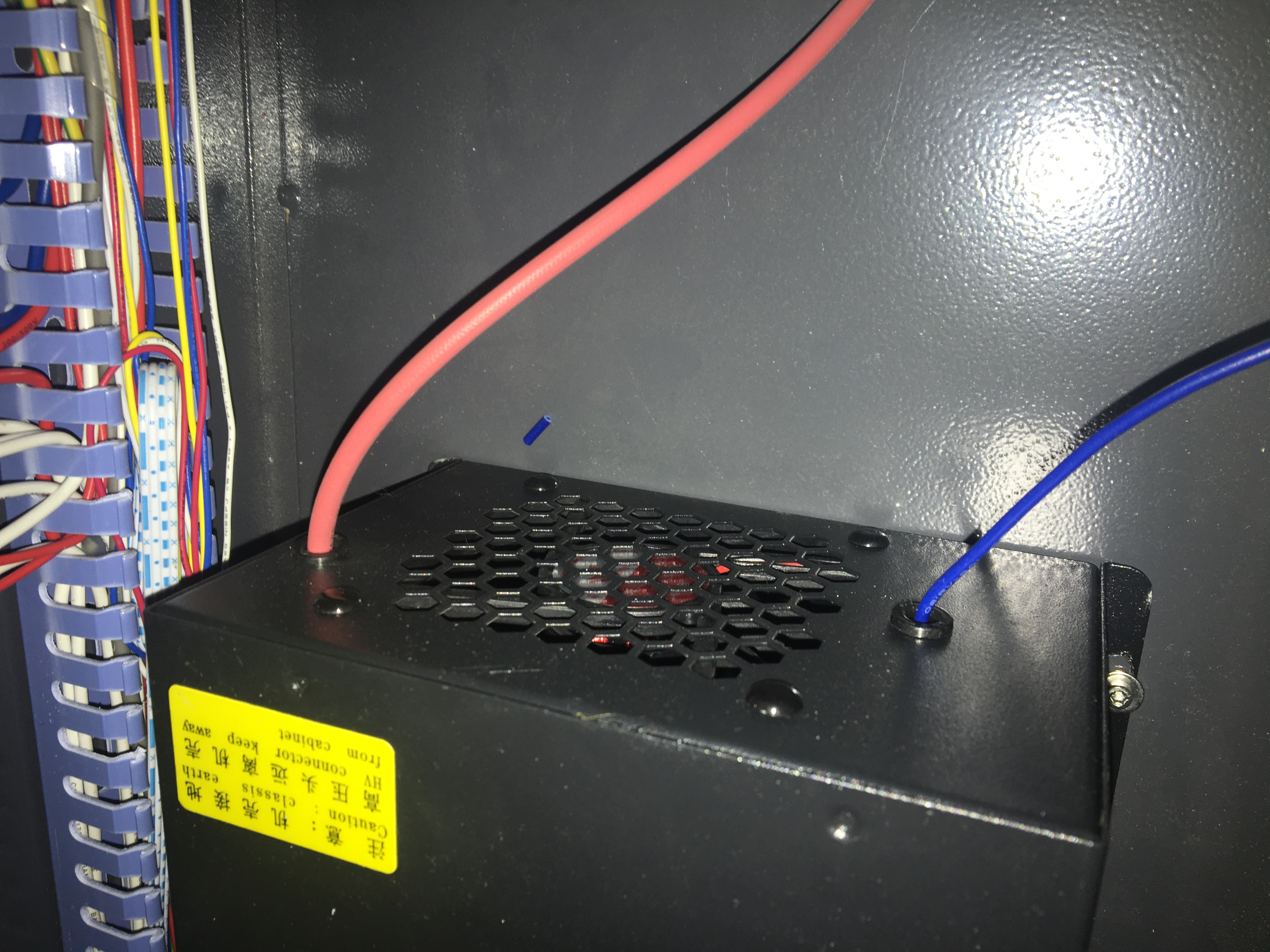
Great! You’ll need to splice the ammeter into that blue line then.
