Hi folks.
My eagerly awaited diode laser has just arrived from China. In the end I went with one which was mentioned here in the forums - a 40W (10W optical) diode laser.
I eagerly attached it to my completed chassis, connected it via a 3-pin supplied cable (having checked that the pin-out was correct - PWM, 12V and Ground match the controller).
I switched on, loaded the basic software supplied with the chassis and tried a quick test. Nothing.
The steppers are all fine and the laser moves around as it is supposed to, but there is no sign of life from the laser itself.
So, how to check/diagnose the thing - that is the question.
I have a bench supply, so I can quickly generate any required voltages. My understanding, as far as it goes, is that the laser needs a 12V DC supply to fire, and is thenceforth controlled by the signal on the PWM pin (0-5v). I am thinking, therefore, that I need to hook up a trustworthy 12V from my bench supply to make sure power is getting to the beast. I presume I then need to feed something on the PWR line to activate and test.
Or could it be that I have missed some vital stage - rather like forgetting to remove the special, hard to find packaging on an epson inkjet that locks the carriage and prevents any further progress until done…Is there something I need to do to the unit before it will fire-up?
You should be able to measure both the 12V and the PWM on the laser module with a DVM.
12V: Read 12vdc across it referenced to ground.
The PWM when referenced to ground should read a % of the max pwm voltage. Example: if the PWM signal is max 5vdc* and power is set to 50% the PWM pin should read about 2.5vdc. Alternately set the power to 100% and therefore it should read 5vdc.
*assumes the PWM signal is 0-5vdc.
What controller are you using?
Also make sure the that ground lead to the diode module is exactly the same ground as that of the controllers PWM output port.
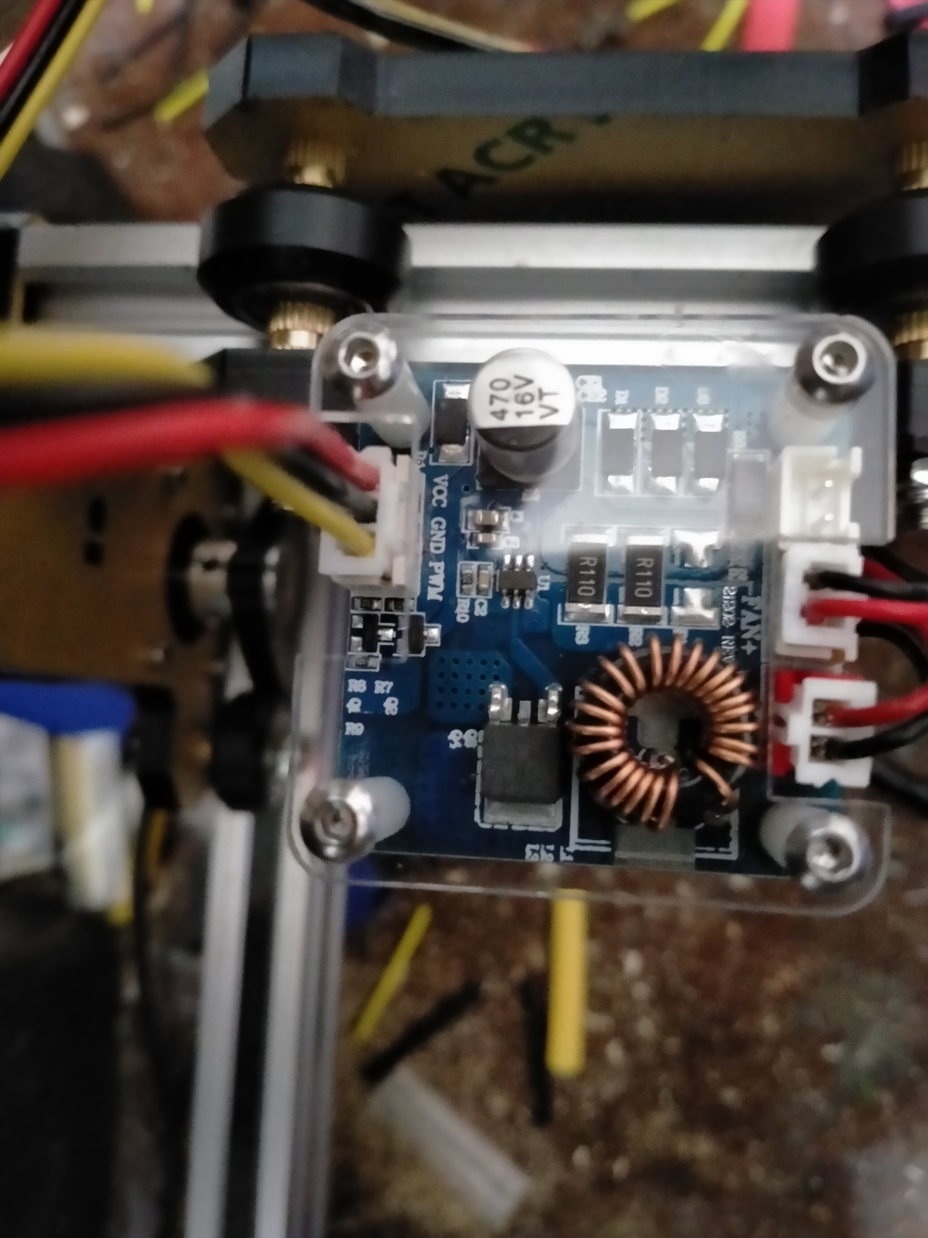
I’m using the unexpected bonus controller that was bundled with the chassis. It is an arduino based x-y controller with an optional laser 3-pin connector which is labelled 12V, GND and PWM. The laser has the same 3-pin connector so I thought it would be plug and play.
After staring at it for ages and finally probing it, I found the problem. PWM and 12V are reversed on the controller. I ran VigoWorks, turned the laser on, and then went probing on the controller with my trusty multimeter. Turned out that the pin labelled PWM was putting out a steady 12V, regardless of the laser setting. Meanwhile the pin marked 12V was producing 0-5V as I turned the laser power up and down. It is as simple as that - I backwards label (though the label IS right according to the colours of the supplied 3-pin lead (R - 12V, Bla - Grnd, Yel - PWM). I simply snapped off sufficient plastic from the female connector on the controller to allow me to reverse the male 3-pin connector, reconnected it and like magic the laser sprang to attention.
It is too late to start testing it now (I’m working in a few hours), so I’ve confirmed that the laser can now be switched on and off, and will line up some calibration and test routines tomorrow, before I do a proper report back on the project as a whole.
There are three sockets on a row. One is labelled fan with a connector, another with possibly the laser diode connected and an empty socket. Any label or knowledge what the empty socket is used for? Maybe a ttl signal input to enable the laser? Just wondering…
Update
The machine is now working. Thanks, Paul, for the suggestion. You may well be right because at the moment the laser fan spins up as soon as I power-on. The extra socket is probably an off switch. Since I don’t really need it, we may never know
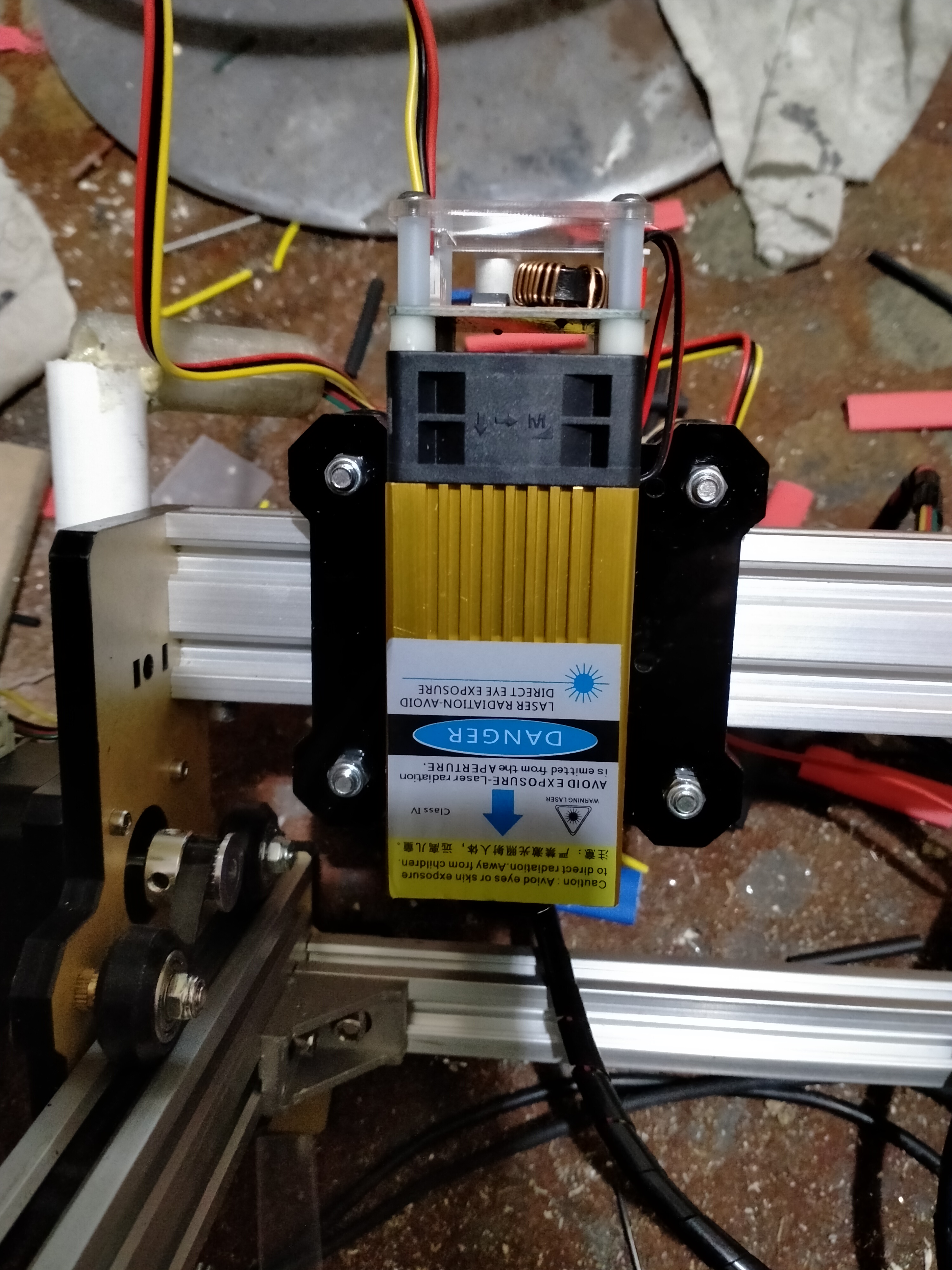
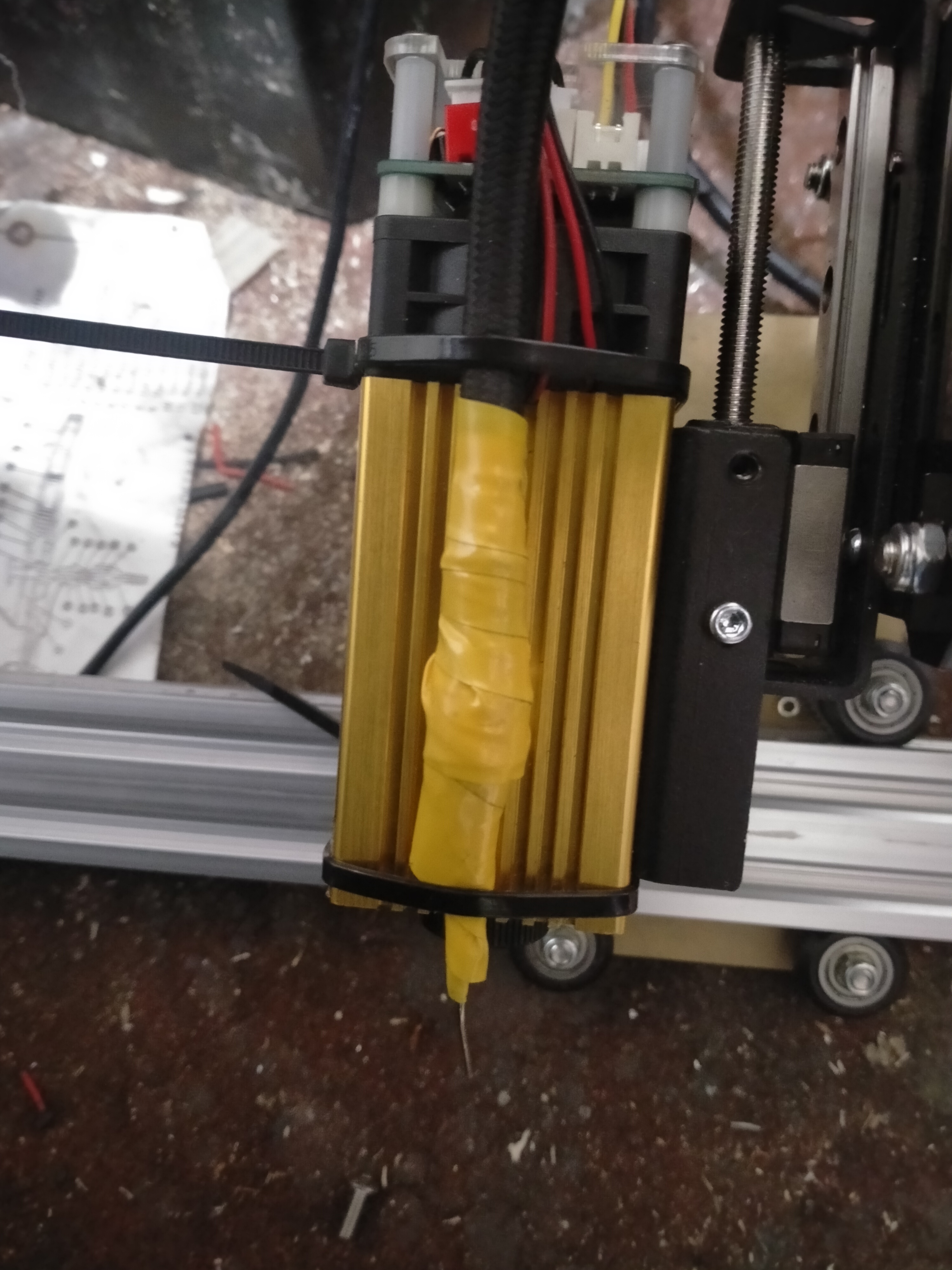
At the moment I am trying to get it focussed properly. I’ve done some test engraves on plywood, and the results are nice - at least as good as I hoped. I’ve bodged-up an air assist for it, using an old airbrush compressor and the needle from a printer-ink-refill kit. This is strapped to the side of the laser and appears to work really well (if a little noisy).
The next thing I need to do is to come up with a bed to sit in the frame. A bit of research indicates that I need a mesh or grid structure to allow air to flow through, so I’m going to experiment with various options.
This shows the improvised air assist.
That link was just what I needed. I’ve ordered a sheet of the 20mm thick 3/4" aluminium honeycomb - it looks perfect for the job and pretty reasonable at about £30 with VAT and delivery. The sheet is about twice the size of my print area so I’ll be able to make a spare (I’m sure the bed will inevitably get
damaged with repeated use - although I doubt the laser will punch through the aluminium unless it is near max power and minimum speed).
It should be delivered over the weekend, so I can include it in the write-up
Having thought about this, I now think that the extra port is for air-assist. The connector is a simple 2-pin, labelled + and -, and when I stick the meter on it I see 12V. I also noticed that the software supplied with the controller has air-assist as an option, which seems pretty conclusive. I’m currently running an air-assist via a separately powered compressor, which, fortunately, is 12V. The obvious thing to do, therefore, is to hook it directly to the controller via the ‘spare’ port.
During testing I’ve discovered that the unit intermittently freezes. The software, displaying the current laser position, shows it hovering at one spot, and the laser-head sits still, with the laser on. It still responds to the software, so I can halt the job, turning the laser off, but clearly this is an issue which demands my immediate full attention. I’ve managed to reproduce the lock-up but, unfortunately, not consistently, so I’m working through a list of suspects, trying to eliminate each. I’ve ruled out dodgy software at the application level by producing the lock using Lightburn, rather than the supplied app. I am currently trying to rule-out other software levels by using an android app to drive it from my mobile. After that I turn to hardware and my first thought is to try a different PSU, since the current one is from ‘my box’, and it’s history is unknown. After that it gets tricky, so I’m secretly hoping it is the psu.
Now, back to trying to hookup micro to mini-B USB…I wish they would all decide on C and spare me endless troubles …
There is a good chance that the 12V provided there is for operating a valve, not for actually powering an air supply, and if you hook up the compressor to it, you might draw enough current to damage the board if it wasn’t designed to supply that much current.
Also, it might not be protected against back-EMF; when you turn off current to an electromagnet (like in a motor) the collapsing magnetic field will present a reverse voltage which can be much higher than the running voltage. It’s easy to kill the board if a diode is not in place to shunt this surge.
If you aren’t sure about how much current it can supply, an alternative would be a remote MOSFET board as are sometimes used for 3D printers. Many of them can take 12V or 24V as input, and switch a much larger current. However, even then many were intended to switch only resistive loads and do not have a diode to protect against back-EMF and so could be killed by switching a motor.
However, I’m pretty sure that doesn’t have a diode in it. The MOSFET on it might have a diode inside it, but those are rarely rated for this kind of use; usually you would also have to put a separate diode across V+/V- to protect the MOSFET.
Hehe…what is it they say ? ‘A little knowledge is a dangerous thing’. I never even thought about the mechanics of the pump/compressor. I just saw 12V and thought sweet…
I’m, grateful (and possibly richer) for the correction. Fortunately the ‘lock up’ problem means that I haven’t fiddled with the air-assist, so no damage done
I changed the PSU for the unit - replacing the one of unknown origin for one I was saving for another project. It supplies 12V at up to 20A, so there should be Watts to spare. Unfortunately the unit once more locked-up, about halfway through the test, which seems to indicate that the PSU is not the issue.
Damn,
Now I have to assume the controller-board is the issue and devise a way to test… The only thing that springs to mind is trying another controller (which I don’t have). I noticed that the nano on the suspect controller is socketed so I think I’ll try switching that first (I have plenty of nanos). Don’t you just hate ‘intermittent’ faults ?
Hmm…the controller is ground for everything since it has the only supply. Unfortunately the board is multilayer so I can’t trace grounds by eye. One possibility is the USB cable. I’m using an extra-long cable for convenience (the unit is on my bench until done, and the computer is on my desk several feet away). I wonder if USB ground on the computer vs ground on the controller could be an issue? Easy(ish) to test - I’ll move the unit next to the computer and use another cable. OK…wish me luck
Looks like it was the USB cable. I moved the unit next to the computer and switched to a fairly standard cable. Since then I’ve done 2 of the 3 test prints with no glitch or lockup. Still to soon to call it, but the previous failure frequency indicates to me that if I complete the third test print without issues then I’ll be confident to continue my general testing and tweaking unless and until it happens again.
Further to this…
I wanted to be sure that the USB cable was the problem, so I did some more testing using the suspect cable. Turns out that the chance of lock-up correlates with speed of print very closely. Above a certain level it almost inevitably locks, and as the speed is reduced so the chance of lock-up diminishes.
The little I know about electronics (I learned Karnaugh Maps & Boolean algebra on my Computing degree but very little practical electronics) would lead me to suspect that this is could be a dirty signal resulting from a dodgy cable. As speed increases then the signal degrades (and smears) to the point at which the ‘5V’ signal drops below switching threshold, resulting in gibberish.
Changing to the shorter USB cable seems to cure the issue - I have now done enough test prints that confidence is high.
I’ve been thinking on this…let me run my idea by people here as a sanity check.
Now that I have a nice meaty 12V PSU, I figure that I can solder-up a relay so that the controller port just supplies the control signal, which activates the relay, turning on the air-supply with power directly from the PSU. That would put almost no load on the port, and at the same time would allow the air supply to be controlled from software as normal.
Is there any potential problem waiting to bite me, or will this work as I think…?
This is super common with CO2 lasers, but is perfectly reasonable in any case; it’s very reasonable for thiis to have cured the problem.
Relays are inductive loads. You are energizing a coil that pulls the switch, and when you turn it off, you have that same collapsing magnetic field. This is why if you buy an “arduino relay board” you’ll find that it uses an optocoupler to isolate the signal from the electromagnet.
A MOSFET is basically a solid-state relay.
When you switch an inductive load (like a motor or relay) with a relay, that same back-EMF voltage spike that can kill a MOSFET “tries to” arc the contacts in the relay, and they will eventually be likely to weld together.
If you have ever experienced “water hammer” in pipes from turning off a faucet, it’s basically the physical analog. You need to do something to absorb the spike.
With a relay, you can use a “snubber” (which is a resistor and a capacitor, or just a capacitor with some intrinsic resistance called “ESR”) to reduce the spike to a level that doesn’t damage the contacts. A MOSFET might be more sensitive, and a “crowbar” diode across the motor poles is a better choice than a snubber for a MOSFET.
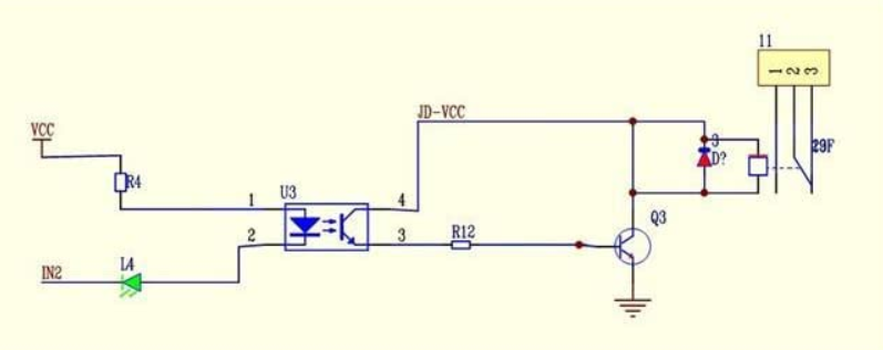
Here’s an example of a relay board that has the “crowbar” diode installed to protect the optocoupler and driver transistor from back-EMF from the coil:
Here, in the schematic from that page, you can see in red on the right the diode (“D?”) that protects the driver transistor (“Q1”) and optocoupler (“U3”) from back-EMF from the coil.
It doesn’t have protection on the other side because that is application-specific. Some people use two-channel boards for bidirectional motor control of a single DC motor (I don’t like this because then software can connect both sides at once; a short circuit from a software bug) and if it had a crowbar diode, that would be a guaranteed short circuit.
You could put a large (exact value doesn’t matter at all) electrolytic capacitor across the motor terminals, or a (say) 1N4004 (or larger) diode across the motor terminals. You need to attend to polarity; if you get it backwards you’ll release the magic smoke that is meant to keep it working.
I hope diodes are still relatively cheap even with the current supply chain difficulties, but also you can usually scavenge them from dead electronics; lots of old electronics will have multiple diodes to scavenge…
For that particular board, this particular comment describes how to connect it to your control board. You’ll want a board with similar capability.
Nothing is ever simple. I know…
You might hook up the air assist to one of the relays, and see how long it lasts. If it lasts forever, you are good. If it welds in the on state, you put a snubber or crowbar across the other side and switch to that side.
Just over an amp. I hooked it up to my bench supply and set the voltage to 12V and set current to max. The pump fired up and the current spiked and quickly settled down (less than a second). The meters on the supply won’t give me an accurate reading for short term spikes (it is cheap and I wouldn’t expect it to). Starting it several times, the peak seems somewhere between 1.5 and 1.7A - but that isn’t much better than a guess to be honest.