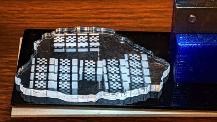
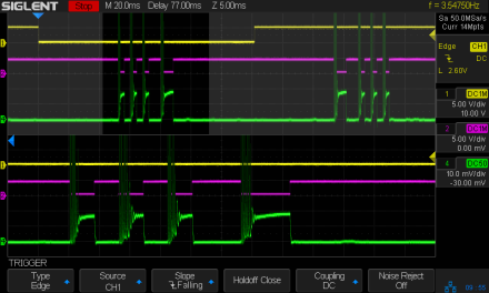
Laser glitching around text

  • In this case the power level = DF(internal LPS) * DF(pwm-L) ;
  • Both PWM’s control power. This means that the product of IN and L DF determines the power. The L in this case functions as an enable and part of the power control.
  • There is no enable other than the PWM-L signal not being asserted [DF =0] .When no imaging is active the laser is off.

In this case the power level = PWM-IN
The enable is L. So I assume that this line is asserted for the entire time an image is being created. However, I have not measured such.


I think the IN was intended to be an analog control and the L is the digital on-off control.

As I understand it the original K40 only dithered so all that was needed was an intensity control pot and an on-off function.

When we replaced the NANO controller with Gcode control the debate about how to use the IN and the L arose. Actually, that is what prompted me (and a few others) to fully document the LPS design

It appears in the Ruda application the IN was chosen to control power with a PWM and the L as the enable.

In my experience controlling power only in the source imaging program ignores the need to adjust for tube changes. To each his own.


I wonder if all this dialog is getting us closer to finding this problem. :confused:

a few of the open source / 3DP controllers have built-in stepper motor drivers but most have sockets for stepper motor drivers so you just purchase the drivers you want and plug them in at a cost of ~$5ea to $25ea on the high end. The motor connections are all done on the main 3DP controller board. The “external” drivers needed for a Ruida setup have a higher cost and much larger footprint mostly because of extra costs of connectors, mounting hardware, plastic casing and labeling.

I picked up a $50 MKS Sbase v1.3 board for my K40 and everything but end-stop wires just moved from the M2Nano to the MKS board. For the end-stop wiring, the M2Nano had 3 pins for the end-stop( X-gnd-Y ) with 2 wires crimped into the one ground pin. The MKS board wanted a 2-wire pair for each end-stop and I could have kept it with the grounds tied on one connector so the other end-stop connector was just the signal wire but I broke them out to X-Gnd and Y-Gnd connections.

IMHO, all of this has ‘evolved’ from existing commercial equipment and changes are made to lower costs for the hobby sector. Those that can’t afford a $20k machine. A friend of mine that supplies my acrylic (scrap) from his commercial business has an American dual laser tube machine with a Ruida controller. His previous laser had a trocen and it was wired the same as my Ruida. It had an accident with acrylic and honeycomb that ended up in a significant fire in his shop.

The most simple interface is one that is already used by existing, more expensive commercial equipment. On a laser the single most expensive part is probably the controller. Most of the early controllers used a variable dc to control the spindle (spindle speed = laser power). I’ve also noticed that many of the newer or lower cost controllers have done away with the analog control.

The Ruida, Trocen and other commercial controllers have been around much longer than the K40 and it’s associated hardware. They also allow you to ‘store’ the code and don’t require a computer to connected to actually control the hardware.

I think the K40 controller is a very cheap, yet ingenious device. Just by leaving out the ‘laser enable’ signal removes a lot of the ‘head ache’ on what the controller/software has to do. They just make the power a manual control. Removing this from automated control greatly relieves that K40s signal interface.

In the end, they both do the same thing, although I have to admit, the K40 controller/software is really an incredible creation. Always wish I had purchased one. Of course my sights are a bit higher now.

The L-On1 → L is active only when the laser needs to fire. Not sure if that’s what you meant. The pwm is separate and runs for the entire time the layer is executing, even while the head repositions itself to lase another object.

Now that Lightburn has ‘sub layers’ it looks like the same thing happens as it switches to a sub layer that sub layers pwm is immediately present.

The Thunder laser DF212 only has a pwm output and a ‘ttl+’ and ‘ttl-’ for firing control. The - is for the L input, or it’s inverted + for the H input. No analog output…
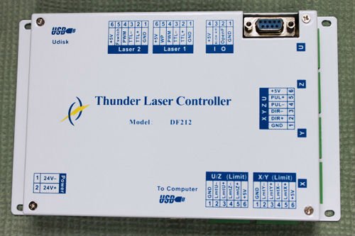
thunder-df212

I understand completely, to me, this isn’t the argument.

In a commercial environment when maintenance is paid for and routinely done, this isn’t an issue. It’s also not wanted in a commercial environment. You have a person with no technical knowledge, monitoring the equipment (maybe 20 of them) as it does the same thing over and over. Having an adjustment accessible to the operator that can damage the equipment is the last thing you want around in this situation.

I’ve had mine for over a year, I check it monthly and I have not had to change the lps settings up to this point. I expect to as it gets older, like me, won’t have a much ‘go’. I use a Mahoney wattmeter or Russ’s dohickey…

You, I and most of the people here are not the average user and certainly not the hired ‘hourly’ worker to watch over this stuff…

I’ll have to admit that I have gone into the Ruida console and bumped the power when I get a run of mdf that has more glue in it. A pot may have been handy there.

Also note if you wanted to use a Ruida for an LED laser that uses the pwm to fire the laser, you would have to add some kind of ‘and’ gate to generate the pwm only when L was asserted.

I wish… but don’t think so… Think we ran out of ideas.

The only part of this issue is that there appears to be a ‘fixed’ amount of time that it ‘fails’ in this way. As you change the speed the area that ‘fails’ is closer of further away. So it appears to me the lps isn’t really shutting down. I sometimes wonder is this is something that can occur with the tubes chemistry and is lasing at a lower power level or …?

I was hoping that @dougl could explain more of what he was talking about for an r/c filter… I’d try anything to ID what’s going on here.

I’d still put my money on the lps…

Sorry about the diarrhea of the mouth… I need to get going…

Talk to you later…

P.S @donkjr the hv meter failed. The resistor stack is apparently not working and I am building another one with higher precision resistors. I think the epoxy must have expanded or shrank enough to break the connection. Figured it was the meter, but it works, who’d thunk it was the resistors. Never thought I’d miss it. Also, I have no equipment to measure 600mOhms :poop:

:smiley_cat:

Well, it seems I’m seeing the same issue with my 50W. (KT332N controller)
I was etching a name tag on a plastic gold tone over black name tag blank. Just using the plastic protective film it came with as the masking.

I hadn’t noticed this before, which I theorized was due to the pulses not penetrating my normal masking.

Masked another blank using my normal masking and the glitches are not seen. So if your masking is heavy enough you can work around this if it’s a problem. Still would be nice to have a hard fix.

2 Likes

It should not be ‘pulsing’ in that area of the graphic… I’ve seen this on a few machines. Some show it occurring on only one side if set for unidirectional engraving, instead of bi directional.

You’re right, thicker tape isn’t a ‘good’ fix…

:smiley_cat:

Ok, it’s a random and spurious output of energy of extremely short duration. :crazy_face:

2 Likes

Wasn’t trying to be offensive, but it must be lasing to do that. I’ve seen a number of these and most of them have changed out the tube, controller and lps and have the same issue… It would be nice to know where this originates.

It was interesting on one, where they disabled bi-directional engraving and the aberrant spots show up on the trailing side of the engraving only.

:smiley_cat:

1 Like

No worries, I didn’t think you were trying to be offensive. :wink:
Has there been any commonality relative to the quality of the LPS?

I haven’t seen it fixed but lots of parts seems to have been changed out in many of the instances. One person has had the vendor replace all the main parts. Others have taken a more one shot, like the lps, but no one that I know of has shed any light on this anomaly.

I keep hoping…

:smiley_cat:

1 Like

I seem to remember someone mentioning that it took three different power supplies to finally alleviate the problem on their machine.

1 Like

Yeah, I’ve been noodling through the long thread on the Lightburn discourse.

It’s looking more and more like an LPS issue but nothing definitive yet. Some have found it does this in a narrow power range like 18 or 20% and when they changed power to be outside that range it didn’t product the sparkles.

1 Like

Some people advise not to run at a low power level because you can’t count on the lasing reaction at the low end of the range… I’m wondering if it’s in some kind of ‘more’ excited state. IMHO, it’s a hardware problem, probably not rfi. I’ve gotten my share of ‘bad’ new parts…


One person posted a screenshot from one of the controller makers that recommends raising the minimum power level ($30, in grbl,I think) to somewhere around 5% so the tube would respond faster as it’s kept at a higher energy state… I didn’t buy into it…

:smiley_cat:

1 Like

At or below 4ma the tube will have a hard time ionizing reliably.

2 Likes

Just to close this out, Ed Nisley over on the Lightburn forum posted about what he found and blogged in detail. It turns out that the LPS at low power output( < ~30% PWM on LPS-IN ) has some LPSs sending power glitches on the output even when the Enable signal on LPS-L is off/High. I don’t know if this will show up when the LPS is controlled like a stock K40, ie DC voltage on LPS-IN and PWM on the Enable signal/LPS-L.

Ed’s proof it’s in the LPS as it’s controlled only by Ruida with PWM on LPS-IN and Enable on LPS-L.

Ed’s test rig setup.

2 Likes

Interesting, thanks for the update.

2 Likes

Is it just me or does the LPS vendor show 3 ways to connect and use their LPS and none of them are wired as Ruida recommends?

Operational manual of CO2 power supply1523409284190.pdf (182.4 KB)

Looked at the pdf… They looked the same as a Ruida or a K40 type… What specifically is the 3rd way… I don’t remember three…


Ed and I have discussed this many time (still ongoing). I say his lps is broken simply because the control line does not have the laser enabled to fire, yet it’s firing on it’s own. Three decades fixing this stuff, that’s exactly how you diagnose a bad component.

If you follow the control signals, it goes in correctly but the output is wrong… This is 100% the lps failure by simple diagnostics. He states it’s low cost components and other things, but the simple fact is it’s lasing when it should not. It’s probably highly related to what Ed mentioned (cheap), but the lps is broken, nevertheless.

He has been able to re-create it with another lps, but mine runs a lot at below 12% with no issues like this as do many, many other users… So the simple answer is he has two broken lps. I wish I had a nickel for every time I’ve replaced something with a ‘new - bad’ part.


I’ve tried to come up with a good way to try and trap what’s causing it and Ed did a great job… He has a current probe for his scope that I am lacking. I do measure the mili volts across the mA meter, but that’s the best I can do for now. I have a partially built probe, but it’s really noisy…

I 100% agree that’s what’s happening, but if it were common all of us would see this and we don’t.

Still boils down to a bad lps.

:smiley_cat:

2 Likes

That makes perfect sense Jack when the LPS is being used as the manufacturer recommends but the Ruida isn’t doing that and so far none of the other controller owners have reported this and all other controllers drive the LPS as the manufacturer recommends. That is:
LPS-L is the only dynamic control signal going into the LPS
LPS-IN is a fixed and unchanging voltage

This is why I brought up the fact that the Ruida modulates both LPS-L and LPS-IN and if there’s something about this causing noise in the LPS which kicks off the stray firing pulses.

Until an LPS that’s twinkling with dual Ruida controls is also shown to twinkle with the standard single dynamic LPS control( on LPS-L ) then I’m not sold 100% that it’s the LPS.

I will take any LPS’s which are twinkling and pay for shipping(<$20) so I might be able to see if I can make them twinkle with both a Ruida controller and a GRBL, or Smoothie, or M2Nano, or…

1 Like

The ones I’ve seen are only Ruida and only a few of them.

I’m of the opinion that the lps was designed to be modulated, pwm or driven with DC to the IN of the lps.

This would be normal for a cnc machine. The K40 connect the IN with dc, in essence same as the Ruida set using L-AN1. It only changes when the new layer has a different percentage.

I don’t think the Laser ON was ever meant to be used as a pwm input.

I can’t say I can tell the difference between the two types of connections… Except, IMHO, it’s clear the K40 isn’t really limiting the mA from the supply as is the Ruida.

This can only be controlled with the internal current limit…

If this was an inherent flaw in the lps, we’d all see it no matter what drives it… To me it’s a major reach to associate how the control signals change as related to this issue.

This would make them virtually useless.

I think the real only fix is a new lps… People have changed them out with the same results, however I think they are as Ed suggested, barely on the ‘pass’ scale when tested.

It’d be nice to identify a single component failure in these things… Most of us don’t go inside the lps case… I have a defibrillator and it can be set off from contact like this… don’t need that… :frowning:

You seen to have it in for the Ruida … lol

:smiley_cat: