There is such a huge overshoot of the actual scan area…
If she is running 600mm/s I think that overscan is expected.
![]()
She/original poster had been using 300mm/s but when it was said to up power she also upped speed. I think that video was posted by one of the others who’ve come in stating they had the same problem.
Attached is an edited video.
- The head is slowed down before a random dot (RD) is imaged.
- There is a stop frame added when a random dot is imaged.

Observations;
- The move prior to the RD is not a random move. Rather it is the continuation of the vertical scan. This refutes my assertion that there is both a random move and then dot fired.
- This means that anything in the control path could be generating the RD including the controller and the LPS.
- The dot period is very small, there is no flash when it is created…
- The dot is imaged directly under the head suggesting it’s not a reflection.
- It’s hard to be sure but I perceive that the dot is placed in line with the vertical scan …
- No new enlightenment!
Just thought: I believe there are example conditions (but not in this video) where the RD’s are outside of the vertical scans that have information in them. Does this infer that an RD can occur on any scan whether there is an image programmed or not?
Things to try:
- Create a program to scan vertically but with no image. Would this still result in RD’s?
STILL A MYSTERY!
2 Likes
Since the glitching comes AFTER the engraving, we need a way to isolate the controller signal from being the problem. Maybe by slowing down the PWM so it can’t do the glitch. Or some way to turn off the L/enable when it’s not doing the expected engrave sections which would validate something internal of the LPS was glitching the LPS output causing the dots.
IIRC the Ruida’s put PWM on both L and IN with the IN signal setting max power and is a steady period PWM and the L input is where the design control pulse train is happening. If for some reason the Ruida PWM control line is glitching low and causing these dots, can’t that be eliminated with an R/C pullup filter( to 5V ) circuit on the LPS-L input line? If we can eliminate the possibility of a glitch from outside the LPS then the problem has to be LPS internal.
I don’t think this is always true, is it?
This only occurs only raster imaging right?
Does the RD ever occur during a vertical scan over white space?
I believe it is true. If bi-directional engraving is turned off then the dots only show up on one side of the engraving. That tells me it’s happening before or after and from what I’ve seen in slow-mo, it’s actually happening after the engraving.
I don’t think people have seen it while doing vectors since the vector moves are often inline with previous vector’s start location so the glitches could be hidden. A specific test pattern would need to be devised. But I suppose a bunch of short vectors would prove that true or false. You understand that an engraving really is a bunch of short side-by-side vectors.
Horizontal line patterns were also tested and the engraving direction was rotated 90 deg and indeed the glitching dots showed up when raster engraving in the vertical axis too.
Now you can. lbrn was already in the list and lbrn2 just hadn’t been added. Fixed that now.
1 Like
Maybe I do not understand the symptoms clearly?
Perhaps we should start a thread and clearly outline all the;
- Knowns
- Suspicions
- Tests
From the video, it looked to me like the RD’s were created only when the head was moving in the vertical direction. The RD’s were created when the head was moving down the stage and also up [although infrequent] up the stage.
From this and the test where the angle was rotated 90 deg I concluded that RD’s are only created on vertical moves.
So for the vector test, I was thinking:
- Draw a short horizontal vector (a few pixels wide).
- Move down the page vertically 1/2" [creates vertical white space]
- Draw another
- Do this for a few inches and stop.
I was hoping to minimize the amount of burning so we can just see the RD’s.
Film the above as before if there are RD’s present.
Questions this may answer:
- Are any RD’s created? [if not then this relates specifically to rastering]
- Are any RD’s created in the white space between rows or only in the areas where there is imaging?
** If RD’s only occur in relation to areas of imaging the source may ***more likely be the controller
** If dots occur during moves the source is ***more likely to be LPS noise
*** or not ![]()
We could then convert the above to a bit map and repeat in raster mode(s)?
In these 2 photos it was shown the RDs happened with both X and Y directional head movement.
The top image can be confusing since it shows a mirror with vertical lines having dots and it shows a mirror with horizontal lines with almost no dots. The problem lies in that there was a misunderstanding and the operator did not rotate the scan angle 90 degrees. So in both of these images/tests the laser head was moving/scanning bi-directionaly along the X axis.
In the 2nd/bottom image the horizontal lines also had the bi-directional scanning rotated 90 degrees so the laser head was scanning in the Y axis and lots of RDs were being made.
What was also determined was that if the scanning was changed turning OFF bi-directional scanning, then the dots only showed up on one side of the scan lines. I did not get an answer to my request of which side but the slow mo video seems to show the RDs show up AFTER the engraving task.
One other observation was that if the scanning speed is slowed from 300mm/s to 150mm/s then the RDs were found much closer to the engraving object.
Last observation so far was that when engraving, scanning in the X axis, a grouping of circles the RD pattern seems to create a laying down hourglass shape along the center line of the group of circles with far fewer RDs towards the top/bottom of the grouping of circles.
There is only one pwm from the Ruida going to ‘IN’ of the lps. The only other control is L-On1 or laser enable, wired to the L of the lps.
If you put an r/c filter on the Ruida pwm you would loose control of the pwm period or limit it in all probability. It would also slow the response time of the lps. IMHO this is generally a bad idea.
If these were so susceptible to rfi, a lot of us would have issues like this… we don’t.
Rfi is rarely the offender and the idea of adding r/c filtering is, I my mind, ludicrous with this kind of equipment.
I don’t think I (we) know more than the people who engineered it and has these controllers running all over the world without these filters or other hacks. I just don’t think hardware modification is a good idea here.
Nothing here points to the controller. Just the idea that the same code has different ‘dots’ indicates the controller is probably not responsible… not to mention they’ve been changed out.
![]()
Time out:
When troubleshooting an elusive problem I have learned that there is no such thing as a “ludicrous” idea.
Although often not the final solution, trying lots of stuff, some of them ludicrous, can reveal the root cause of a ludicrous problem.
I have also learned that just because something is engineered by a “company” with lots of customers does not necessarily mean that they engineered their product optimally nor that it classifies them as experts.
Time In:
2 Likes
I understand there are 2 signals from the Ruida, one is a changing PWM and the other a squarewave. I’ve been calling them both PWM but will now change. As for signal naming, I really would like some consistency and just use LPS labels. And for clarity, the two different wiring setup for these LPSs are:
Ruida:
PWM to LPS-IN
SQUAREWAVE to LPS-L
All others:
SQUAREWAVE or DC VOLTAGE to LPS-IN
PWM to LPS-L
As for why I was mentioning an R/C filter was not to fix the problem but to try and eliminate a possible source. A troubleshooting mechanism since none of those currently having the problem have nor know how to use an Oscope but could connect up a couple of leaded components. I never mentioned RFI and the R/C filter was not about RFI.
“probably not responsible” is exactly the thing I was thinking needs to be eliminated… I’m not a fan of “probably not…” in troubleshooting and there are all Ruida controllers showing this problem and some have even swapped in other Ruida controllers and still have the problem. I just don’t think this eliminates Ruida as a possible source. They all have different LPSs and some have swapped out the LPS and the problem continues but we heard someone swapped the LPS out a 2nd time and the problem went away so new parts can still have this problem.
We are not going to get these users inside the LPS… ideas on how to definitively eliminate the Ruida beyond “probably not” status?
If it’s a digital signal it is a ‘squarewave’, that’s how digital machines work. And the pwm is also a squarewave…
It’s probably best to call it what it is, which is ‘laser on/enable’ hence the mnemonic ‘L-On1’ for ‘laser on 1’, since it supports two lasers.
If you revert to the lps and yours looks like this:
Mine looks like this:
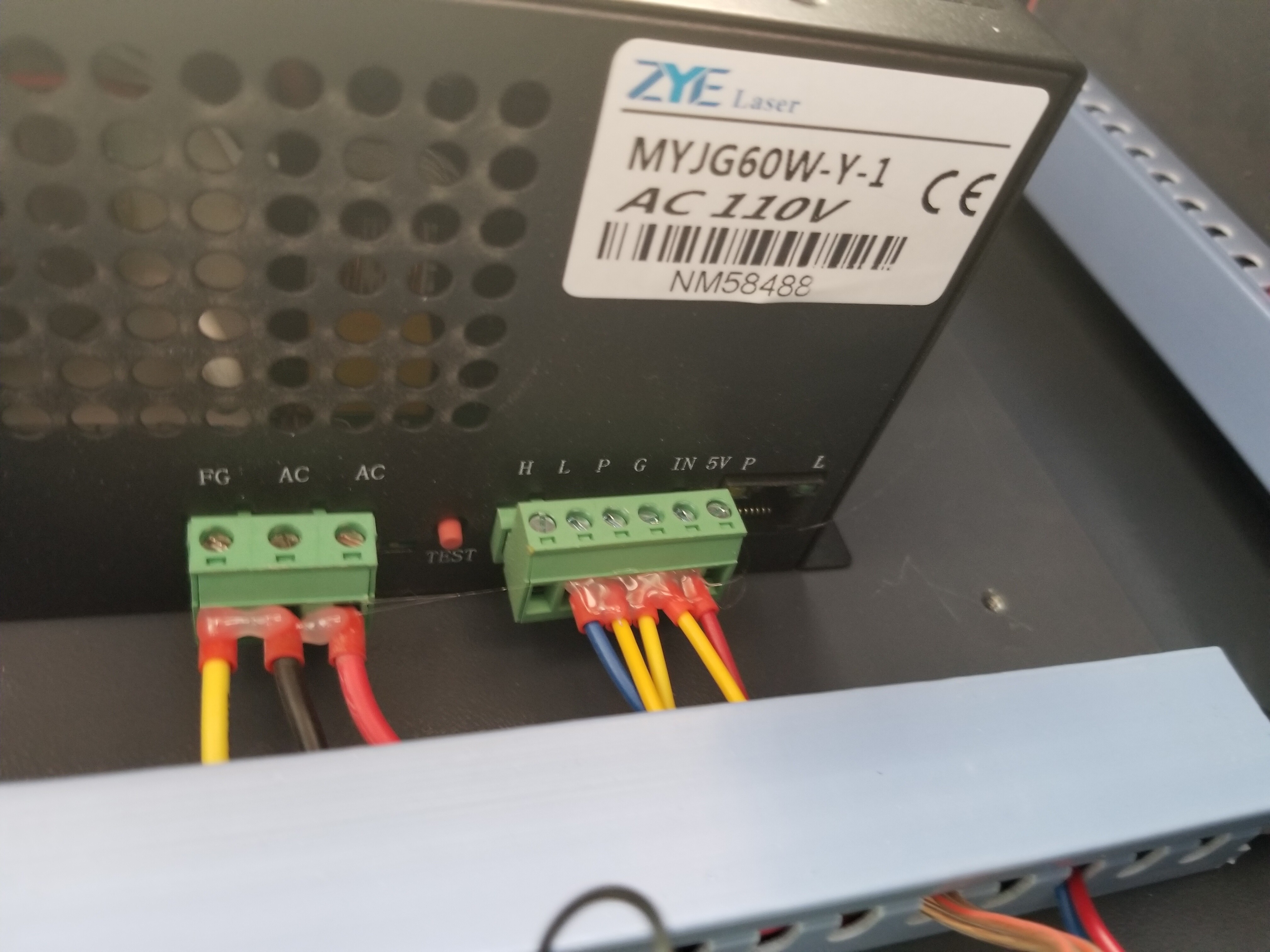
How clear is H, L and IN used as a reference to ‘your’ lps. The naming convention varies with the manufacturer. They are pretty inconsistent.
There was mention of emi… if not emi/rfi, what would you be attempting to filter.? Did you have a specific frequency in mind?
I’m not trying to pick on you, but I think I’m not understanding what you are attempting. I’d like to try about anything at this point to clear this up. However it has to be something we can actually do.
3 out of the 100’s of thousands? We don’t know how many there are out there with a Ruida and this issue, along with how many are out there doing this with some other controller…
I’ve mentioned many times in both threads that the only real common denominator with this problem is the lps.
I had a problem with a commercial computer system. The cables were over $3k each. I went through three pairs and no go, finally broke down and got another one… it was a bad cable… been there done that…
I’ve thought about how I could use a scope with this issue. There is no way to trigger it. If you can’t trigger it off something useful, it’s not a great help.
I know there is a ‘fixed’ delay, as we slow it down it’s aberrant dots are closer to the source image. Even if we knew the delay, it’s so random you might just keep missing it. So I don’t think it’s of much help here.
What I don’t want is a fixation on something that’s not possible to prove.
My money is still on the lps… ![]()
![]()
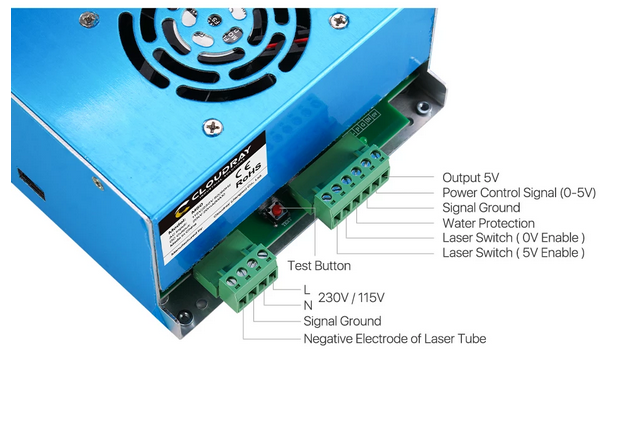
Are you telling me that the Power Control Input( LPS-IN ) is getting a varying TTL square wave, ie having pulse width modulation? The Power Control Input?
I must have missed when that was stated because I thought it was just a fixed period and fixed duty cycle signal used only to set the max power output of the LPS. If so it’s just not anything any of the other controllers( non Ruida ) take advantage of and if there were a benefit I would think the developers would have jumped on it long ago. Many systems just put a stable DC voltage on that Power Control Input( LPS-IN ).
Now the other signal is what/where I thought all the magic happened with regards to controlling how the laser was putting marks on materials. And that signal LPS-L or LPS-H and labelled as Laser Switch(0V and 5V) enable on the Cloudray picture. There, an ever changing pulse train is output by the controller and controls the pixels being marked on the material by the laser.
Personally, referencing the signals by the LPS names/labels makes more sense than mixing labels by controller output label and LPS label. Many here are far more familiar with the LPS-IN and LPS-L labeling used on LPSs found in K40 and K50 machines.
Unfortunately none of this discussion is eliminating any part of the system from the problem originally stated…
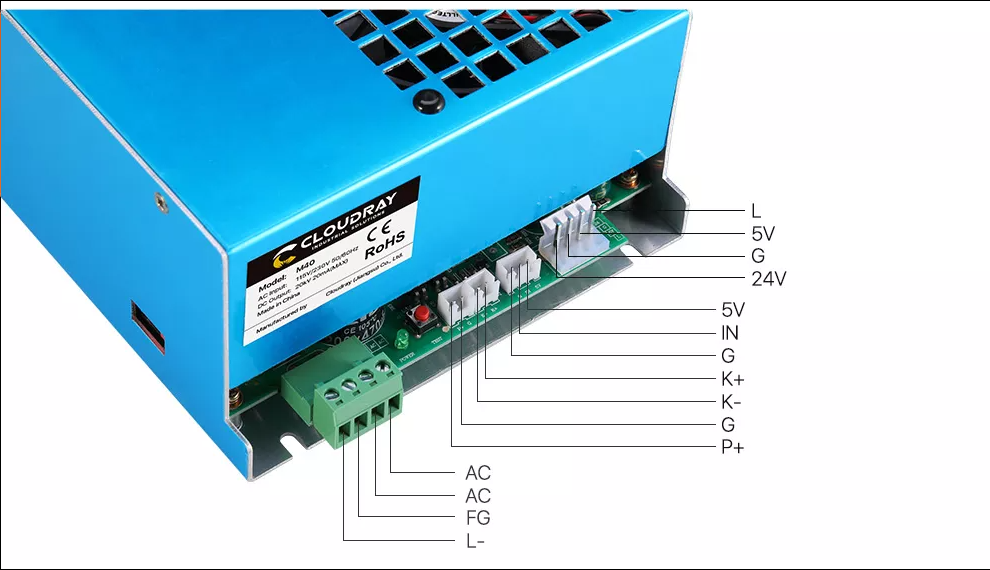
Yes, that’s the original lps design. There are really two inputs to control the lps. IN is the power control. L is to enable the laser to lase at whatever power level IN is set.
- K40
- pot → IN
- pwm → L
- Ruida
- pwm → IN
- L-On → L
When laser enable goes low the laser will fire at whatever the IN setting is. If the IN pwm is 0% then the laser will not lase. If it’s 50% it will be ‘on’ 50% of the period.
Take a line as part of a fill. On a single pass, when it gets to the proper place the L input goes low and it stays low until the line is complete. The laser is lasing at the IN or pwm rate. The L input is active for a longer period than the pwm or power is set. You get an average ‘power’ over the time L is low.
The K40 sets the pwm on the IN pin, usually with a dc voltage. This is a pwm setting within the lps and is equivalent to feeding a pwm signal to that pin like the Ruida does.
The K40 now uses the pwm to enable the laser. When the pwm is low on the L pin, the machine lases at whatever the ‘pot’ setting (pwm) has been previously set. This is what limits you mA and gives you the ability to set 100% with the pot. When the pwm from the K40 is applied to the L input it enables the laser for that period, which lases during that period at the IN setting.
Does any of this make sense ?
That may apply to you and yours that hang around with the K40 crowd and own one… It took some thought to figure out what the h**l the K40 was doing the way it was wired up. It seemed bassackwards.
Realized it had to do with money, ![]()
@donkjr was instrumental in helping me understand what’s going on with the internal workings of the lps and the K40 interface… at least the tip of the iceberg. ![]() I thank him everytime I see his icon
I thank him everytime I see his icon ![]()
A big part of this was being able to get my scope on it and actually watch it. At least the control signals.
“Laser ... enable” == “laser enable”
All the L input does is ‘enable’ the laser to fire at the IN ‘power’ level.
![]()
So on the Ruida the “pwm → IN” signal is a varying pulse width modulated TTL signal?
I figured it was equivalent to the fixed DC voltage often used with K40s with GRBL or Smoothieware firmware so that LPS-IN is set once and never touched again… But I guess Ruida does this differently and instead of a never changing 2.5DCV the Ruida puts out a 50% duty cycle pulse train for some period of time and changes this when the layer change in the design has a different power level. I didn’t see that in your Oscope screen shots but then again it was a very small window of time.
That is quite different from how the K40 GCode based controllers drive the LPS. Besides, I thought from your Oscope traces the laser was burning at different intensities because on each pixel the PWM signal put on LPS-IN was a certain width which limited how many laser pulses were fired on that pixel. The laser frequency fires at a much higher frequency than the controlling PWM.
If the Ruida had drivers builtin I would wire it up to my K40 and look at this on a scope since I have a Ruida controller in a box but no stepper motor drivers.
If you set the percent power in your software to 35%, it will generate a 35% pwm output from the Ruida to the IN of the lps. It’s set from the executing layer.
With the K40, you are setting the pwm with the pot and turning the laser on and off with the L input, with the K40s pwm.
I have lots of questions about how parts of this works. Most of it is not easily found or measured. I’ve noticed the hv is present if the tube is lasing or not. I’m suspicious that it’s there and only increases enough to let the tube start conducting.
Also keep in mind that the speed you can put down ‘dots’ is dependent on the lps response time.
Motor drivers for the Ruida are about $22 each, last time I looked…
![]()
The stock K40 with the M2Nano controller is that way and the only ‘gray scale’ like control was via dithering. But once you replace the stock controller with one which does a different PWM on LPS-L then we are able to do grayscale even though LPS-IN is fixed at some maximum power output level. I don’t know the specifics of what’s happening on LPS-L but anyone with a Cohesion3D board or any Smoothieware based board and even GRBL firmware can do power control off of one PWM signal going into LPS-L while LPS-IN is fixed at some maximum level and everything below that is 100%-0% power range set in LightBurn.
Sounds like the Ruida is more like the M2Nano but with digital control on LPS-IN to set the power level per layer. And I’m surprised if that were a better way, why are none of the open source firmware developers doing this. odd.