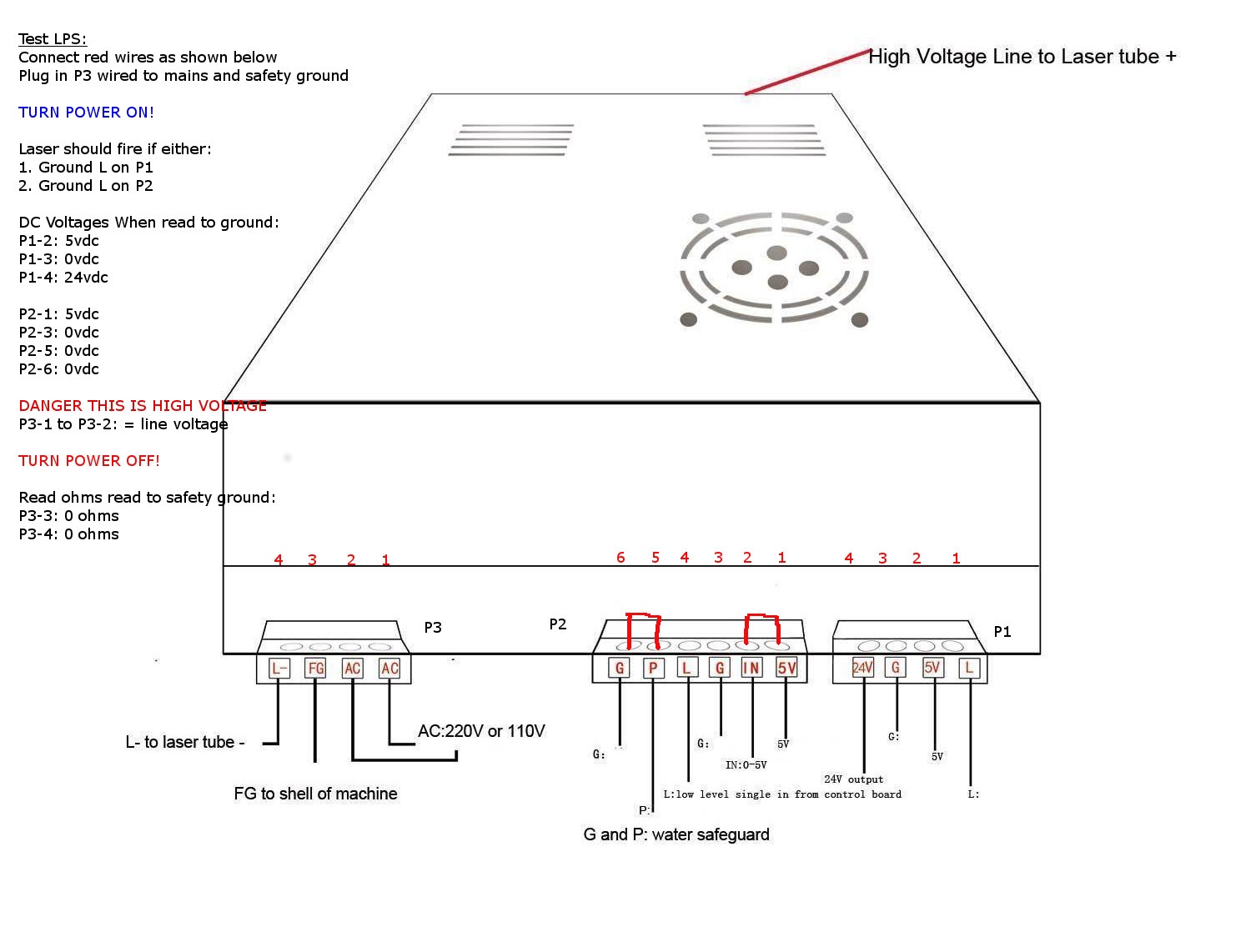
If L is never going low(0V) and the laser fires as soon as P is allowed to go to low(0V) then I would think your LPS is bad. To prove it you only need 2 pieces of wire.
0) depower the system
remove all wires from the low voltage side of the LPS( right 2 connectors)
connect a short jumper wire between the IN signal and the 5V connector
connect a short jumper wire to the G wire next to the P signal
power up the system and then momentarily touch the other end of the wire to the P signal.
If the laser fires your LPS is not working properly
If the laser does not fire, connect the wire to the P signal, connect a 3rd jumper wire to G near the L signal and then touch the wire to the L signal. The laser should then fire only when you touch L with the G wire.
Yes and the computer controls the laser firing by pulling the L signal to 0V.
The P signal must be at 0V or the laser will never fire. As stated earlier, the P signal is the Protection signal and it’s purpose is to protect the user from accidental firing of the laser. Normally it is a way to have everything powered up and operational yet control in a very coarse manner the laser firing. Example, normal operation with the laser creating a pattern you see the wood catch fire and open the lid to put out the fire. The opening of the lid will stop the laser from firing but the laser head will keep moving. The lid switch opened and the P signal no longer was connected to Ground so it goes up to 5V and the laser stops firing.
So P is only the Protection circuit. The L signal is the Laser fire signal and it is used to test fire the laser and it is used by the controller to fire the laser to make designs. It is an active Low(0V) signal just like the P is an active Low(0V) signal and when the L signal is at 5V the laser should never fire except for only one case and that is when someone pushes the fire button on the LPS itself.
Hi dougl, No there is no other power supply. My keyed switch (“Switch Machine”) does exactly the same as your rocker switch that is switching the 240VAC power supply to the LPS.
The wiring to the ‘Power Switch’ is basic; P goes to the ‘Power Switch’ then to the common on the lid switch, then from the N.O to G (next to P).
After carrying out the testing (thank you) unfortunately it appears that my LPS is faulty. I was beginning to think this in the early stages that’s why I asked if there was some type of switch that is stuck in the closed position. At least I think we’re on the right track now. I’ll dismantle the LPS today if I get a chance & yes I have enough electrical knowledge to be dangerous! I’ve having a quick look at some info & electrical schematics on “Don’s Laser Things” and will refer to that more later.
If there wan’t also a “Laser Switch” up next to your temp display I could understand wiring the "Power Switch inline with the lid switch to the P signal. But maybe they all are tied to P and once you have all those ducks liked up then the L signal is in control. That is when the LPS is working correctly.
Look for some solder blobs crossing signal traces when it’s not supposed to or a diode in backwards. You know where to look so good luck and do make sure the HV is bled low.
Note: typically LO and L are connected internally on the board and are therefore the same signal. You can check with a meter.
Please let me know if this it true for this LPS type as I may have an error in my schematic.
It does seem that LO/L is getting grounded with the P signal however your measurements do not show that?
I have seen this kind of behavior when there is a bridge or bad diode in the LPS test button circuit, although the table does not show P controlling L?
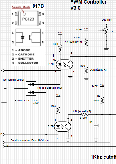
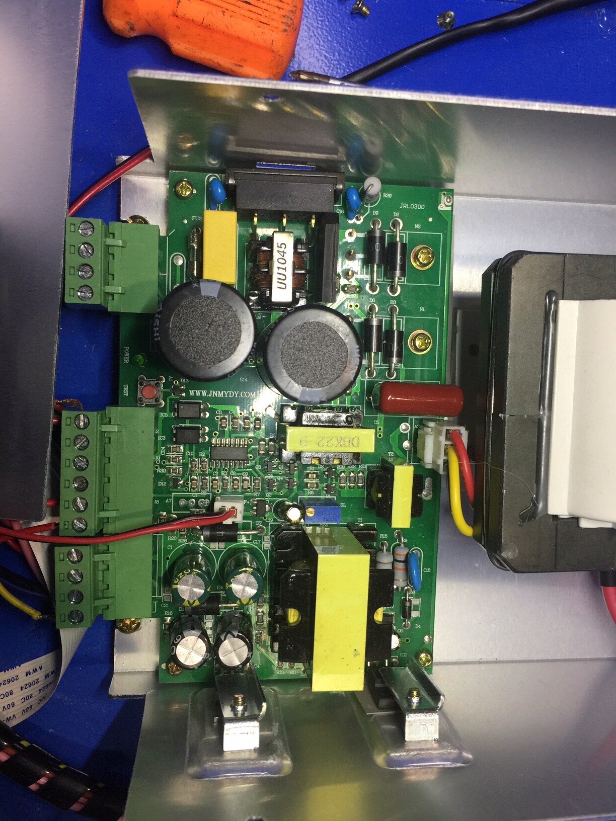
Thanks donkjr. I will hopefully get a chance to investagate further tomorrow and will check (if I can) if L & LO are connected internally. I have been thinking for a while that there must be some type of internal switch that has faulted and remains closed and I would not be surprised if it’s the one in the middle of your schematic which appears to be the same as the one at the bottom. In my attached photo, are these the pair of chips (PC123) located just above the ‘TEST’ button? Cheers.
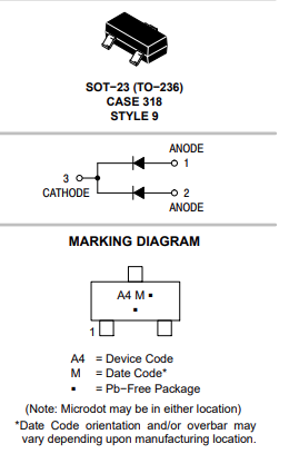
The dual diode package is the small 3 pin chip right next to the TEST button and those look like the two opto-coupler ICs/chips (one for the L circuit and one for the P circuit ) just below the diode chip.
I recommend you remove the wire connectors if you’re going to be checking resistance in the circuit or at lest remove the wires from the L and P lines since it seems something is shorting those lines together.
Thanks for the other layout. Didn’t have much time today, my wife keeps giving me jobs to do!
Test 1: “dougl” gave me similar info to you a couple of days ago and therefore I came to the conclusion that the LPS is faulty.
Test 2: Not connected.
Hopefully I’ll get more time tomorrow and I can check if LO and L are connected internally as well. I did not that pins 3 & 4 on the PC123 chip nearest the “Test” button belled out but the same pins on the other PC123 did not. Does that mean that the second one is faulty? Maybe there’s another reason for the difference.
It is hard to reliably test IC’s in-circuit as there may be surrounding circuits that create misleading readings.
The behavior of your supply [i.e. it fires when P is grounded] suggests that there is somewhat of a short between P and L. Outside of that, the supply seems normal?
Therefore, I suspect the diode array connected to the test button A4W. Alternately there maybe something on the backside of the PCB or connectors creating this problem
That said, the measurements, do not seem to support this theory. In these irrational cases I just keep testing stuff until it makes sense…
Did we measure the resistance between P and L anywhere above?
Don, IIRC Alan measured the voltage on L with nothing connected to it and P pulled to ground and got 0V and previously(before pulling P low) he measured 5V. I don’t believe any resistance measurements were made.
Thanks again for that extra info.
I did have a win although short lived and things may now be worse.
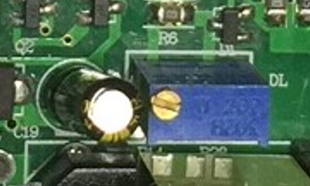
I found that there was a 7.4 M ohms resistance between L/Lo and GND and on close inspection of the PCB I found that the metal cased earthed capacitor next to the adjustable potentiometer was touching the brass adjustment screw on the pot. After moving that over a tad plus separating some other components I was not getting a reading . I temporarily put the PCB back and made all connections bar P1 & P2 terminals. I powered up and pressed the ‘Test’ button on the LPS and the laser fired, I then proceeded to carry out ‘Test 1’ and when I touched the loose end of the wire from GND to P there was a “cracking” sound but no flashes or smoke; I then pressed the ‘Test’ button on the LPS but the laser did not fire .
I have removed the PCB again but cannot see any obvious damage. Not sure where to go from here.
Yes L & Lo are on the same circuit when checked at the soldered terminals under the PCB. P2-5 is not connected to either P2-4 or P1-1.
“Belled Out”; apparently it’s an old saying for checking continuity; they used to use a bell in a circuit nowadays we get a sound from our digital multi-meters.
Can a test be carried out at the three pins on the LPS where the Flyback transformer plugs into, if so what voltage should I see? This to test the circuit between the 'Test" button and the three pins, if nothing there I guess the LPS is faulty. Cheers.
@GlassBlaster,
I highly recommend that you stay away from the flyback and its connections when power is on. There are lethal voltages there and are very dangerous.
.
Is this the adjustment screw you are referring to? Most capacitors of this type have nonconductive sleeves on them.
What was your conclusion on the state of the diode array that I have been pointing you to test?
Is this the adjustment screw you are referring to? Most capacitors of this type have nonconductive sleeves on them.
Looks ok; Pins 1 to 3 and 2 to 3 both read 0.57 ohms; no flow the other direction and no flow between 1 & 2.
I’m now at the stage of contemplating purchasing another power supply, especially now that the laser does not fire after hearing that “cracking” sound.