Hi, newbie here. I recently purchased a used Digital K40 Laser with a new power supply and a known issue that’s not quite what was explained to me via txt messages. I was told that the laser only fires when the the Test button is pressed however I have found that that is not quite the case. The K40 is not connected to a computer at this stage. With the Power & Laser switches On & the lid open and the Test button on the front panel pressed the laser will not fire; it will fire via the Test button on the power supply AND it also fires when I close the lid and stops when I open it! The LED does light when the Test button on the Control Panel is pressed. When I switch the Laser Power switch Off, the display is still On; I tried Test again but the laser did not fire even though the LED lit. The laser power display is currently set at 11.1. Can’t seem to upload any photos of wiring. I’m scratching my head atm so any help/suggestions would be welcomed. Cheers.
The lid of your machine actuates a switch. Where is that switch connected to?
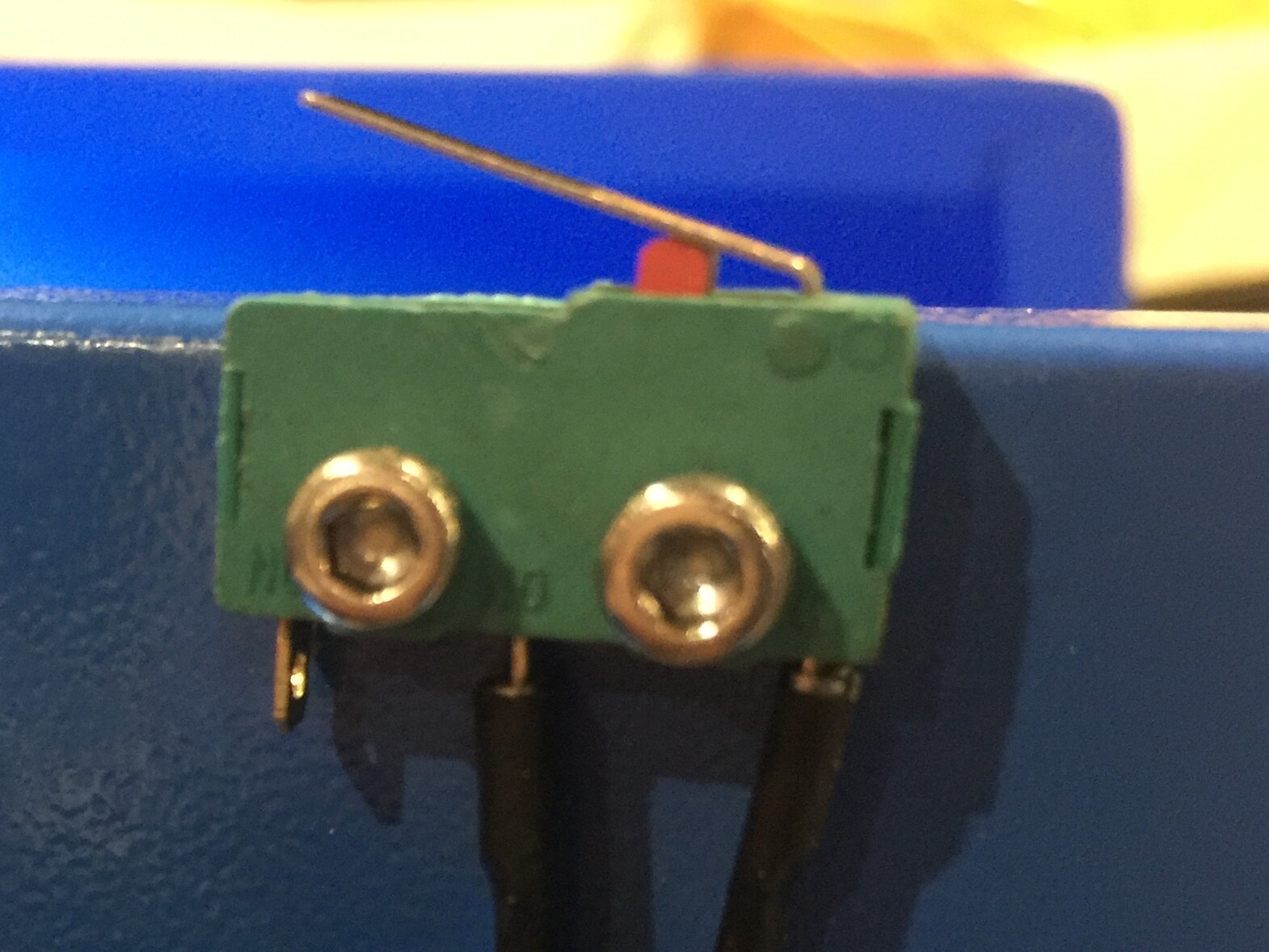
It should be a normally open switch which connects the G and P (or P+) pins when the lid is closed.
Yes the limit switch is connected to those terminals and is N.O. and the laser stops when the lid is lifted.
Could you check/tell where the test button of the frontpanel is connected to? It sounds like there is something wrong with the wiring.
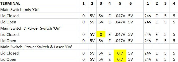
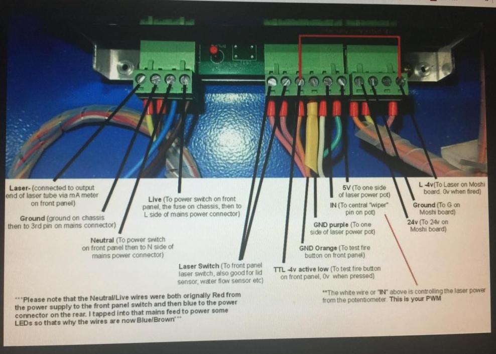
I MAY have found the problem but don’t know how to fix it at this stage. Looking at the pin outs the last one on the right ‘LO’ (laser On) has 5V on it as soon as the Main Switch is turned On, apparently it’s supposed to be -4V! This is the yellow wire that goes to the Mini Gerbil PCB. As stated previously my computer is not connected at this stage. The red wired from the Test button on the front panel is connected to the seventh terminal from the left ‘Test’ which has 5V to ground. The very first terminal on the left has 0V.
If you are referring to the LO pin on the LPS, if connected correctly to a controller, it should be 5v unless there is a job running then it will be some voltage between 0-5V. It will never be -4V.
We need some pictures:
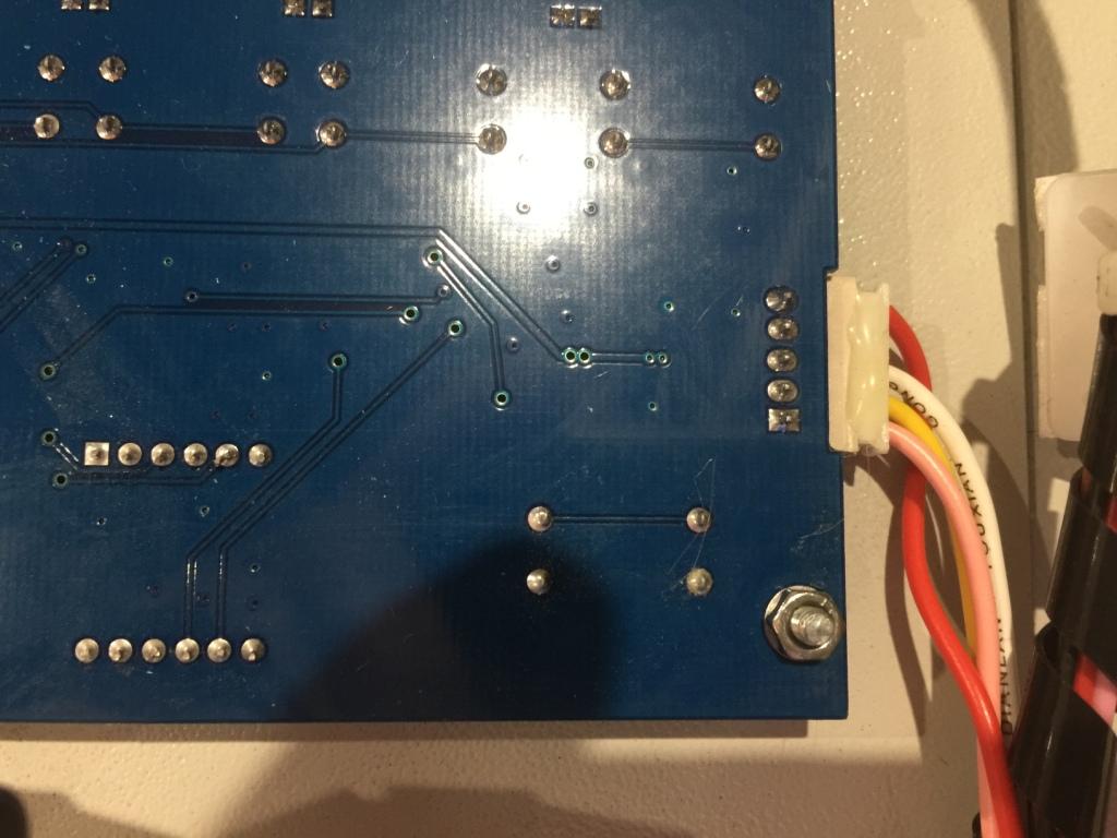
- The connector side of your LPS
- The controller showing as much wiring as possible
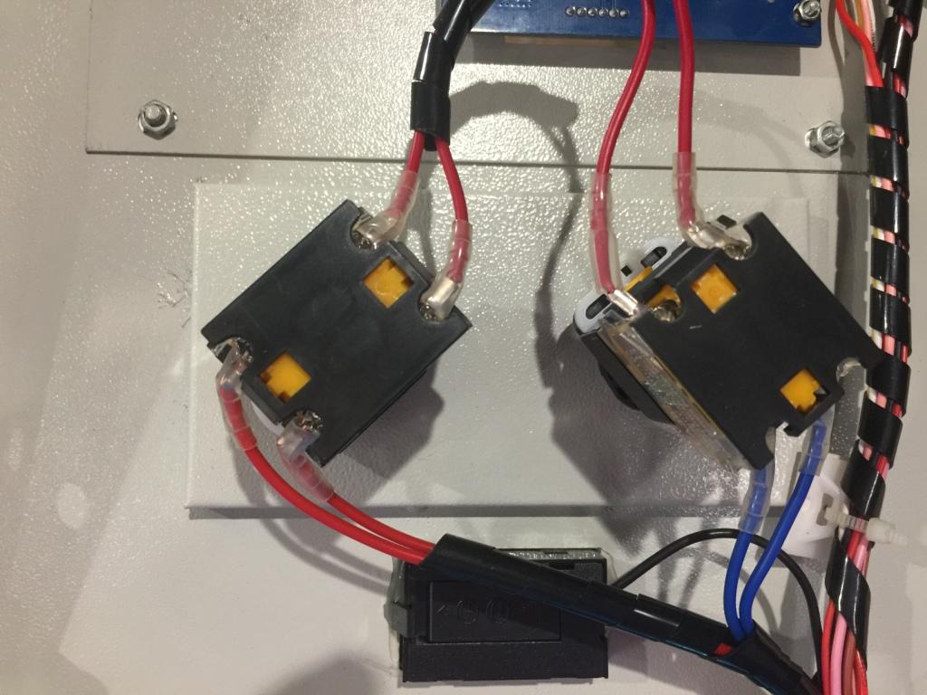
- Any interlock switches that the cover you refer to interpose
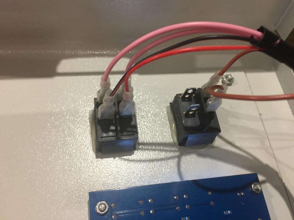
- The control panel front
- The control panel back side wiring
Note: if you machine has cover interlocks then the laser will not fire under any conditions with the lid open. That is except the test button down on the LPS which when pushed will fire the laser independent of the interlocks.
That’s how it should be. L/LO/TL is high (5 V) by default and the laser is fired if this pin is pulled to (i.e. connected to) ground.
More specifically: If it’s off (high), the voltage has to drop to e.g. ≤ 0.3 V to turn the laser on. If it’s on (low), the voltage has to rise to e.g. ≥ 3 V to turn it off. There is some hysteresis to make it decisively turn on or off. This effectively removes all noise and ringing from the control signal.
Is there another power supply? Unless that power supply is exclusively used to power galvanically isolated stuff (e.g. a LED strip or external stepper drivers), its minus should be connected to G.
Anyhow, some pictures and diagrams would be helpful.
I’ll try and put some pictures up, I tried with my first post but all of my text disappeared! I’m getting conflicting info, a YouTube clip states -4V and 0V when firing however there isn’t a wire connected to the second last terminal (5VDC) in the video. “tomatsu” also mentions “≤ 0.3 V to turn the laser On”
I am aware of the Micro Switch/Safety Switch under the laser lid and it’s function, with all switches turned On, when I close the lid the laser fires so this is part of the issue. With the Main, Power & Laser switches On and the lid open, pressing the ‘Laser Test Switch’ nothing happens (because the lid is open) except the LED lights; when I hold down the lid safety switch the laser fires!
Not having a computer connected is not effecting these results I presume?
Ignoring the Mains Terminal block and counting from the left, which terminals are ‘L’ & ‘TL’ or are ‘L/LO/TL’ all the same terminal? I’ll try and upload some photos. My photo showing terminals 1 to 10 (if it uploads) ignoring the Mains Terminal block.
The LPS photo with text is a screenshot from a YouTube clip.

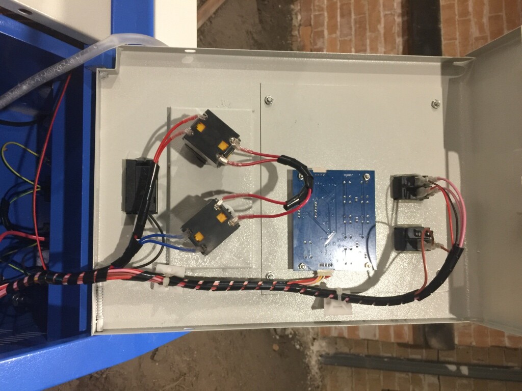
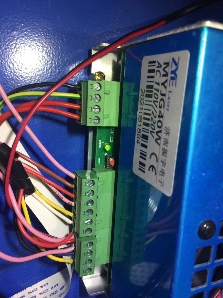
Once you can show us what laser power supply you have lots of things can be mentioned to help.
It is obviously miswired if your laser fires when your safety switches are triggered(lid close). On the stock K40 LPS(Laser Power Supply) there is one input to it which is used to chain the lid switch, water flow sensor, etc so that if any of them “open” the laser will stop. My $0.02 is to say that is where you should start. Ie find a drawing which has the same LPS connections and look for where the water flow sensor or lid switch is and see how that compares to your wiring.
The left 2 wires on the big middle connector shoujld be going to your lid switch…
Far left should be GND and the one next to it to the right should be P. I believe your front panel Laser Enable switch should also be wired to this same P signal but I don’t have a digital panel like yours so the signal could be buried in the digital panel.
BTW, Don knows these LPS’s inside and out(literally) and will have great step by step instructions for figuring out where the wiring is wrong. Getting the door switch figured out should be the easiest.
Yes, they are different names for the same thing.
In your case, it’s the L in the middle (intended to be used for the test button on the control panel) and the L on the right (intended to be used by the controller):
L- FG AC AC G P L G IN 5V 24V G 5V L
According to that table, P (“2”) is always high even when the lid is closed. This means the interlock switch is defective or not connected.
Neither the test button on the control panel nor the controller should be able to fire the laser.
Thanks dougl. The LPS’s photo is above. I don’t have a water flow switch and I’m confident that the lid switch is working as it should. The two issues (probably connected) is that the ‘Laser Test Switch’ on lights the LED, the other is the laser fires when the lid is closed (or I hold down the lid switch). I’ll post a bit more in a tad.
Thanks tomatsu. When I was carrying out more checks the wire fell out of 2 but replacing it didn’t change anything but I haven’t rechecked the voltage. The lid switch does work, when I received the K40 those wires were off so had to find the common & N.O terminal and of course tested at the same time.
I have done some more testing/checking and have come to the conclusion that all wiring appears to be correct. I can’t find out why the laser fires when the lid is closed; short circuit?? I have tested the ‘Laser Test Switch’ at the control panel PCB and terminals 3 & 4 (Test & GND) and it bells out using my multi meter. Maybe a fault with the m2Nano PCB?
Disconnect L in the middle.
Does it still fire automatically?
Disconnect L on the right.
Does it still fire automatically?
Disconnect L in the middle.
Does it still fire automatically? Yes
Disconnect L on the right.
Does it still fire automatically? (Middle L reconnected) No but it made an ugly sound somewhere.
I checked the voltage of ‘P’ where the wire fell out from and it did go to 0V when the laser fired.