Okay. So, if the controller is not connected to the L pin on the very right, the laser does not fire automatically and you can fire it as usual by pressing the “test” button on the control panel?
Well, there is your problem then. If there is nothing wrong with how the controller is connected, then the controller is defective.
Did the machine also come with the old M2 Nano? If not, ask the seller if they still have it.
Since the Mini Gerbil is plug-compatible with M2 Nano controllers, swapping them for testing is relatively quick and easy.
You mean it goes to zero when you close the lid and actuate the interlock switch? You can’t fire the laser when P (protect) is high. That’s the only thing it does. It prevents you from firing the laser if the connected interlock and/or flow switch(es) aren’t actuated.
K40s which do not make use of this safety feature disable it via a short jumper wire (or jumper) which directly connects P to G.
Anyhow, you can verify this behavior. Probe P and G with a multimeter. With the lid open, you should get 5 V. With the lid closed, you should get 0 V. If you do, then in theory it should work fine.
Then put on your laser goggles. With the L pin on the very right disconnected (since your controller appears to be defective), press the test button on the control panel once with the lid open and once with the lid closed. It should only fire when the lid is closed. If it does, then it also works in practice.
Hi Again. Okay. So, if the controller is not connected to the L pin on the very right, the laser does not fire automatically and you can fire it as usual by pressing the “test” button on the control panel? Sorry I removed the L on the left but just tried the L on the far right and nothing has changed; I didn’t think it would because that wire goes to the m2Nano PCB. So the fault remains.
You mean it goes to zero when you close the lid and actuate the interlock switch? 'Yes’. You can’t fire the laser when P (protect) is high. That’s the only thing it does. It prevents you from firing the laser if the connected interlock and/or flow switch(es) aren’t actuated. Yep; the laser ‘Power Switch’ on the front panel is also in that circuit.
Anyhow, you can verify this behavior. Probe P and G with a multimeter. With the lid open, you should get 5 V. With the lid closed, you should get 0 V. If you do, then in theory it should work fine. That IS what happens but the laser fires as soon as the lid is closed so some how it’s being activated. Is there an internal relay (mechanical or solid state)/switch that could be stuck closed?
Then put on your laser goggles. With the L pin on the very right disconnected (since your controller appears to be defective), press the test button on the control panel once with the lid open and once with the lid closed. It should only fire when the lid is closed. If it does, then it also works in practice. Whilst ever the laser fires when the lid is closed I’m unable to test the ‘Laser Test Switch’. I need to prevent the laser from firing as soon as the lid is closed. I though that there maybe a memory chip in the m2Nano PCB that may have an effect but apparently not and I have proven that by unplugging the wires that go to that PCB.
I’m confused. Earlier you wrote about Mini Gerbil and now you talk about m2Nano. Which board are you using?
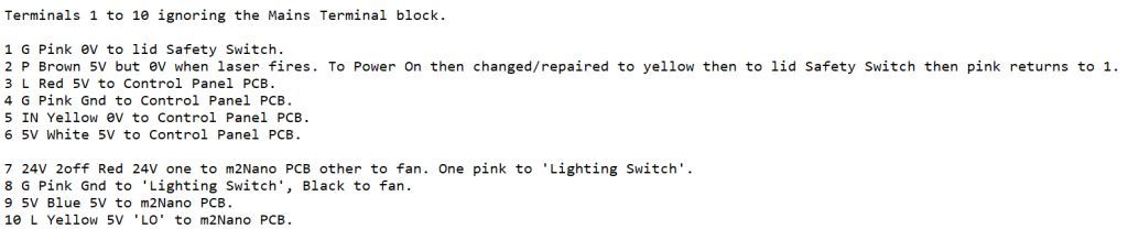
The m2Nano uses a inverted TTL singal on the right L pin to activate the laser (only one pin!). The power is regulated by a potentiometer (analog frontpanel) or PWM (digital frontpanel).
Mini Gerbil uses two pins to control laser and power separately. The right L is used to activate the laser (M3) and the IN pin is used to set the power (PWM).
For me it looks like your LPS has a bad optocuppler on the right L pin, which stay active, even when there is 5V, but should only be active when 0V.
As I’m not familiar with any lasers and from looking at info online I thought that I must have had a Mini Gerbil as I did not know there was other types available, but after taking a photo I can obviously see that it is a m2Nano PCB. Is the m2Nano the board that comes with the K40? Cheers.
With the "Power Switch’ On I thought I would check if the ‘Laser Test’ button was somehow stuck On; it wasn’t. I removed the middle GND to the Control Panel but the laser still fires with the lid closed but it’s a lot brighter, probably 100% because the LCD is not lit. I then replaced the GND and removed the L to the left of it to the Control Panel but the laser still fires with the lid closed but it’s as before not bright because I guess of my ‘11.0’ setting (the LCD was lit). Both these wires are switched by the ‘Laser Test’ button; tested at the LPS.
With the middle & right L’s disconnected the laser still fires when I close the lid. With both the middle & right connectors unplugged from the LPS nothing happens at all which I suppose should be the case.
On your Front Panel there are the following switches:
Laser Switch ( ENABLEs the laser to fire and should be wired to P signal and pulls low)
Laser Test Switch( FIREs the laser for testing and goes to the middle connector L pin and pulls low )
Power Switch( provides AC power to the LPS )
I do not see a laser Power Switch which would be a low voltage switch.
Check to make sure there is nothing connecting either of the L signals to ground. The laser should not be firing when there is nothing connected to the L signals since the internal circuit(LPS) should be pulling those L circuit up to or above 5V when nothing is connected.
Because we are interested in the 5V circuit… There are 3 connections which set the laser power level( Gnd, IN, 5V ) and are located on the right end of the middle connector. What voltage do you measure across the Gnd and 5V signals? If not 5V, try removing those 3 wires and measure again.
The thought is maybe the front panel is shorting out the 5V in the LPS.
Just to give a breakdown of what the laser LPS “needs” to fire via the L signal is this:
P signal needs to be connected to G(ground) and is done so through a door switch, Laser Enable switch, and/or flow switch.
IN signal needs to be pulled high, probably something above .3V with 5V being laser 100% power. Don’t run the laser very long at 100% power but it’s ok for short bursts/tests. The IN signal can be connected to 5V
At this point no other connections on the LPS matter except that AC input voltage is connected.
Now, to cause the laser to fire with the above configuration( P=0V(grd), IN=5V ) the L signal should be sitting above 5V and the laser NOT FIRING but if you connect G(ground) to one of the L signals the laser should fire.
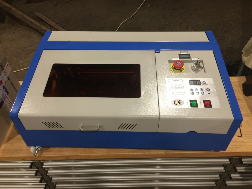
The ‘Power Switch’ is the laser power switch. I did not take a photo of the ‘Main Switch’ (keyed) the ‘Emergency Stop’ switch or the battery powered temperature LCD. (see photo)
There is nothing else connected to the middle L and it has 5V on it all of the time except when the lid is closed and the laser fires; it’s then 0V. The last L goes to the m2Nano that has nothing connected to it at all except the stepper motors and I did unplug it one time but it did not make any difference.
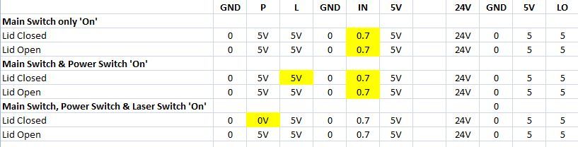
The updated chart below shows terminals Gnd, IN & 5V, you can see there that only IN changes when all switches are On and the lid is either open or closed. They all go the the Control Panel and appear to be normal.
P is OK.
IN as can be seen in the chart ‘5’ does go to 0.7V (the laser is set at 11.0%).
( P=0V(grd), IN=5V ) the L signal should be sitting above 5V and the laser NOT FIRING but if you connect G(ground) to one of the L signals the laser should fire. Therefore one of those L’s must be grounded somewhere and it must be the L in the middle block as the other L only goes to the m2Nano board.
More investigating - I’m getting a headache!
that latest chart looks like I would expect… There are a few things connected which all have to be set to get the P signal to enable( go to 0V ). That’s the lid switch closed and the Laser Switch ‘on’.
The “Power Switch” does not make sense to me in how you are explaining it since it is what should turn on the AC power to the machine. Yes, you also have a safety key switch but I would not expect that metal switch to be connected to AC power. Maybe it’s inline with the P signal…
But after all that and all the things it took to get P=0V I see that L is still at 5V throughout all the tests. I don’t understand how then you say if the lid is open then L goes to 0V when you stated in the chart on the last line “lid open” … P=5V and L=5V
The ‘Power Switch’ switches the power On for the laser and the LCD is not lit with it Off; it does not switch the AC power. The AC power is switched by the keyed switch which is actually labeled ‘Switch Machine’, that switch along with the released ‘Emergency Stop’ supply power to the LPS. In the photo of the opened lid you can see those two switches near the bottom (blue wires in and red out). I have just rechecked it all again. I’m not sure why you say “L goes to 0”, maybe because the original chart at the top shows that but I found P wire had fallen out, the updated chart shows that L doesn’t go to 0V at any stage, P goes to 0V when the lid is closed because the laser fires.
So normally you should be able to have averything switched On and have the lid closed and the laser not fire until you press either ‘Test’ on the LPS, the ‘Laser Test Switch’ on the front panel or a command from a connected computer; correct?
With all switches on G/P go to 0V when the lid is closed BUT the laser fires.
L/G goes to 0V when the ‘Laser Test Switch’ is pressed and the lid is open BUT the laser doesn’t fire because - see “1”.
It’s a Catch22!
Why shouldn’t the laser fire when the lid is closed and G/P go to 0V?
Is there some other power supply other than the LPS(laser power supply) in your K40?
If there is not then everything is powered by the LPS and it is supplied power by 120VAC in the US and 220VAC elsewhere. Once AC power is applied to the LPS and only then can anything else be powered or controlled. So on my K40 there is a big rocker switch with just “ON” and “OFF” labels which switches AC power to the LPS which then powers up the system. Nowhere is that switch directly controlling low voltage power.
Can you follow the wires in and out of the switch labeled “Power Switch” and draw a picture of where they go?