
don if i measure on the pin - of 2.5 and gnd of the board come out 24v this is a problem? the input line of the psu how many volts can it support I would not want to break the psu
at this point, as you say, I could also leave the digital potentiometer of the k40 instead of installing a simple potentiometer or am I wrong? @cprezzi can you help me I can not manage I do not understand why from 2.5 I am 24v

If that pin has 24V on it do not connect it to the LPS.
What does the other pin (1) read???
Trace the pins back to the MOSFET Q4 to verify which pin is connected to the drain.
One pin is connected to the 24V bus
The other is connected to the drain of Q4 which I think is just above the connector.
What is the part # on Q4?
Yes, You can leave the digital panel in place instead of a pot. I did not realize you had a digital panel.
How did you know the current stops at 17 without a ma meter?
I have the milliammeter
1 Like
if i measure gnd and hotbed - i have -22.1v
if i measure gnd and hotbed + i have -23.7v
@donkjr turning in the forum I found this article but I did not understand how to unsolder the led diode d14 to solve the problem of the voltage of 24v on the mosfet?
Do not follow this post! It’s too complicated and doesn’t fit your case.
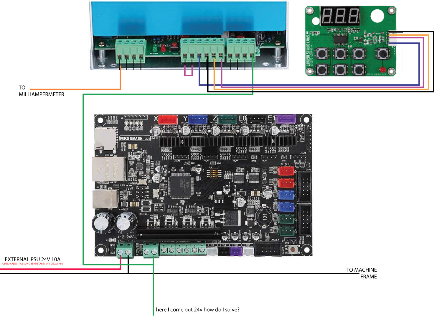
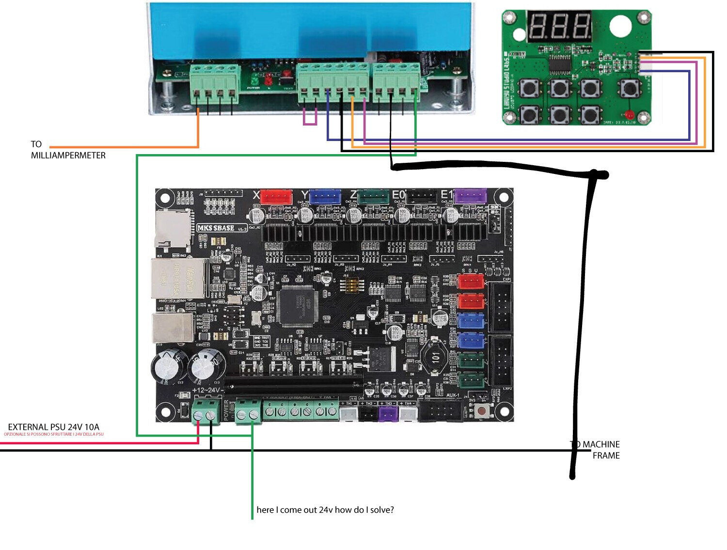
Just connect the - pin of the bed output to the L pin of the LPS (like on your schematics) AND ALSO connect GND of the board to GND on the LPS.
You can not measure the voltage on the - pin against GND, because this pin is floating when PWM is off and pulling to GND when the PWM is on. If you measure the voltage between the two pins of the bed output, you will get 24V when PWM is on and 0V when PWM is off, but the Voltage doesn’t matter, because the + pin is not used!
Think of it like the + pin is directly connected to 24V input and the - pin is connected through a switch (MOSFET) to GND. So the - pin connects the L pin of the LPS to GND when PWM is on, which activates the OptoCoupler in the LPS.
1 Like

Ah! The led diode (D14’s) anode [see schematic above] is connected to 24V.
Therefore when Q4 is off its drain will read close to the 24V bus.
This LED just shows the on-off state of the Q4 switch.
It should have no effect on the connection to the LPS.
If you are concerned about it unsolder one leg of D14 or remove it.
It looks like the (-) pin is the DRAIN connection. We still need to verify.
Are these really negative (-) voltages they should not be?
Is this a measurement error with the DVM leads reversed?
With the power off you can see if the (+) HOTBED pin is connected to the +24 on the input connector labeled POWER. The POWER connector is to the left of the hotbed connector.
With the 24v power unplugged from the board measure the resistance between the pins
+POWER and +HOTBED.
If they are connected the resistance should be close to 0 ohms.
Post the results.
If the +POWER and +HOTBED are connected then via the process of elimination the other pin -HOTBED is Q4’s drain.
Make sure the LPS ground is connected to a GND on the controller board. DO NOT connect the +HOTBED to anything.
1 Like
@cprezzi thanks tomorrow I’ll try and update you thanks to you too @donkjr I’ll keep you updated too
I was not sure if the -Hotend was the drain. there is no pin # on the layout :)!
@cprezzi with this wiring does not work does not give me signs of life the laser does not turn on and off? How is it possible?
@Cama_Work Did you activate the laser with the “Laser Switch” on the digital panel?
Is there some other lock installed, like doorlock or water flow sensor?
the laser switch is activated but also not using the digital control panel and using the configuration with the PIN 2.5 bed nok I answer I can’t understand
This configuration should work.
Are you saying that in this configuration the laser will not fire;
-
with the manual “test” switch on the panel?
OR -
from the running job?
-
Did you make the necessary changes to the configuration file when you changed to this configuration?
Only last question but is it normal that through this configuration the PSU emits very high acoustic hisses?
Does this mean it is now working???
for the msk sbase 1.3 board i have this running on a frame made co2 and a k40 cased one if u want how to wire and are still stuck if you google my name it will come up with my youtube name the same on here as there. i have made a vidoe of how i did mine and been useing for over a year