hi to all I have connected the mks s base to the psu of my laser everything works I only have a doubt the pwm on 1.23 delivers maximum 3.3v while the psu accepts maximum 5v in fact the output milliamps stop at 17 now I wanted to know if and It is possible to increase the pwm of 1.23 to 5v or connect it to another output to have the 5v.
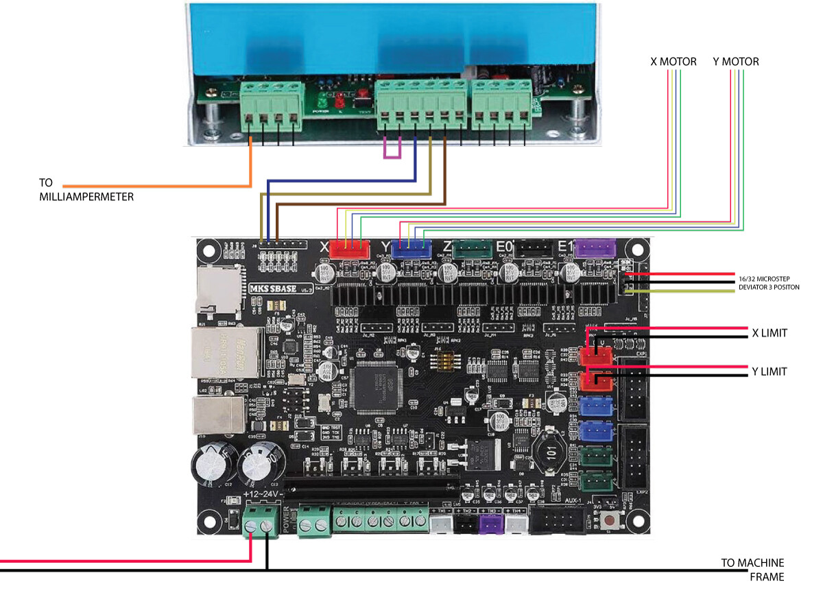
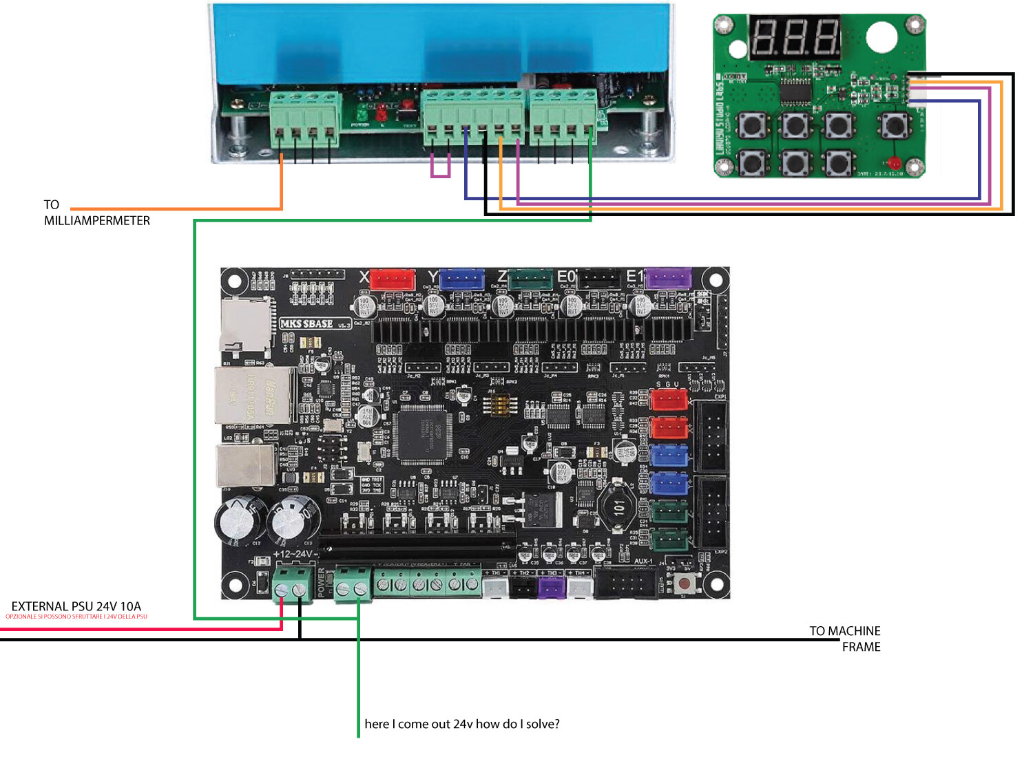
attached my wiring
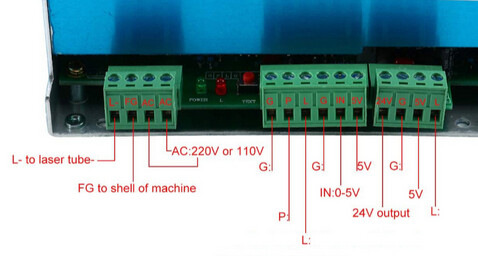
We recommend hooking up the wiper (middle pin) of the potentiometer to the IN 0-5V line to set the maximum power, and using PWM on the L line (using open drain configuration, of course) to control power when running. This way a software bug or misconfiguration can’t accidentally send too much power to your tube and quickly destroy the tube.
You can test fire and set the milliammeter to the maximum power that you might want to use, and then you have the full PWM range available using PWM on the L pin.
3 Likes
I beg your pardon but I did not understand could you illustrate me with signs on my diagram?
You cannot reliably drive the LPS from the J8 connectors as those are 3.3V logic signals.
To drive the LPS inputs: ground true signal are required on most inputs.
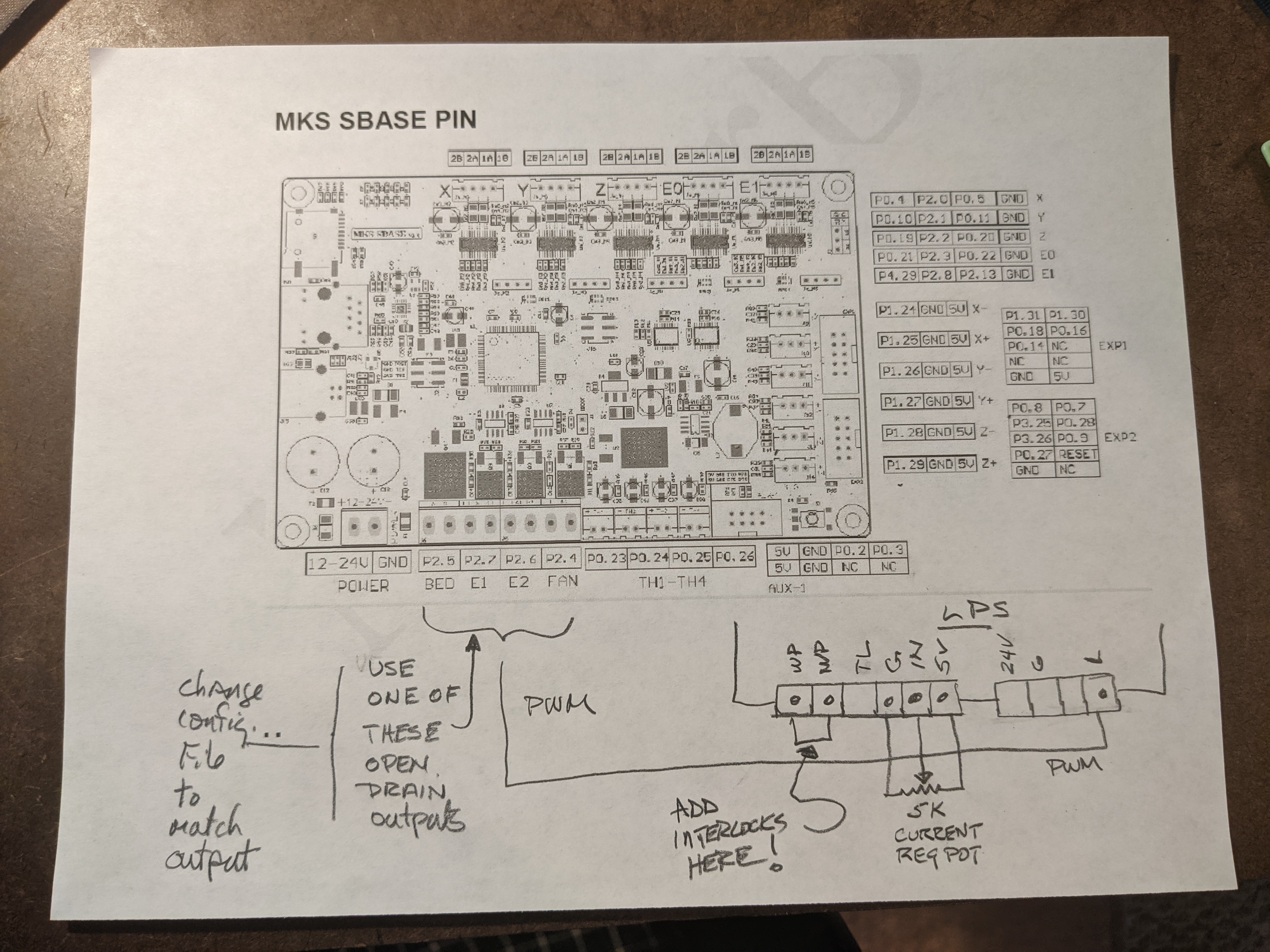
The simplest way to drive the LPS is shown in the diagram below.
I would recommend these changes:
- For programmatic power control, drive the L pin with an open-drain output. Typically I have seen the BED or FAN output used. Setup the config file to match what you chose.
- Add a pot to the LPS-IN pin. This sets the power limits of the tube.
- Ensure that the controllers ground is connected to the LPS ground
- Add safety and water flow interlocks into the WP circuit
- Add a 30ma meter into the cathode circuit of the tube so you can see what current the tube is drawing.
In case you did not know here is a link to that controller’s info: GitHub - makerbase-mks/MKS-SBASE: MKS SBASE is a powerful 32-bit 3D printer control board with LPC1768. Support Marlin2.0, Smoothieware. Support MKS LCD12864 and MKS TFT Touch Screens(SBASE V1.4 support MKS LCD12864A/MINI12864/LCD2004). The motherboard integrates 5 DRV8825 axis and it is use software set current, supports wired network for printing and supports firmware update by SD card…
3 Likes
the output voltage from bed or fan is 24v how can i decrease it?
There will be no 24V if you connect it correctly.
We want to connect to the output of the driving FET’s drain [open drain] to LPS-L.
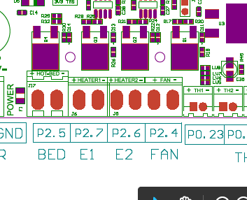
Example: To use the Hot Bed (J17) as the output you connect just the output [drain] of Q4 to L on the LPS.
The schematic below shows J17. The output of its driver is on J17 pin 2. Connect that pin ALONE to LPS-L. The other pin (1) has 24V on it so do not connect it to anything.
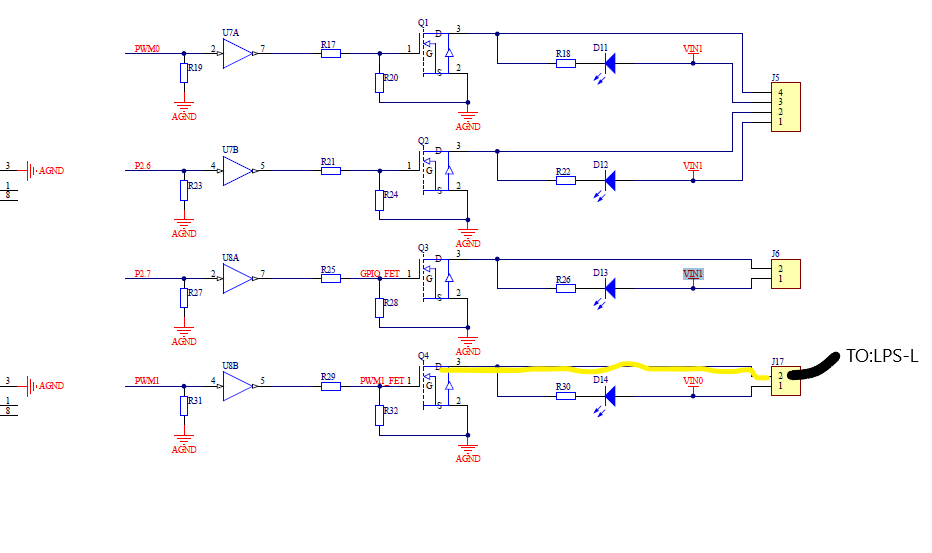
The layout shows J17 with + and - designations on the pins, not pin #s so I cannot tell which one is pin 1 & 2 for sure. It is logical that pin 1 is on the left and is 24V and pin 2 is on the right and is the output [drain] of Q4.
You should check this with a DVM before wiring …
2 Likes
If you have a typical 700x50 or 720x50 mm tube, 17 mA is already too much anyways. There is no point in going even higher.
Anyhow, you can get the 0-3.3 V in the 0-5 V range with a logic level shifter. They cost like $2.
If you can invert the PWM signal in software, you could also connect IN to 5 V and the negative pin of e.g. the bed. [The PWM switching happens on the negative (drain) side. The 24 V pin is always on.]
Then IN is at 5 V and the PWM signal changes how frequently it is pulled to ground. That should also work, I think.
Edit: This needs a resistor.
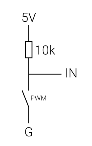
Something like that.
1 Like
FYI:
Logic level shifters have shown to be a problem when driving the LPS input(s) which is not a logic control signal. No need to add more parts as everything that is needed is on the current board.
A pot has shown to be a valuable means of controlling the tube’s power offset as its E/I curve changes over time.
1 Like

don if i measure on the pin - of 2.5 and gnd of the board come out 24v this is a problem? the input line of the psu how many volts can it support I would not want to break the psu
at this point, as you say, I could also leave the digital potentiometer of the k40 instead of installing a simple potentiometer or am I wrong? @cprezzi can you help me I can not manage I do not understand why from 2.5 I am 24v

If that pin has 24V on it do not connect it to the LPS.
What does the other pin (1) read???
Trace the pins back to the MOSFET Q4 to verify which pin is connected to the drain.
One pin is connected to the 24V bus
The other is connected to the drain of Q4 which I think is just above the connector.
What is the part # on Q4?
Yes, You can leave the digital panel in place instead of a pot. I did not realize you had a digital panel.
How did you know the current stops at 17 without a ma meter?
I have the milliammeter
1 Like
if i measure gnd and hotbed - i have -22.1v
if i measure gnd and hotbed + i have -23.7v
@donkjr turning in the forum I found this article but I did not understand how to unsolder the led diode d14 to solve the problem of the voltage of 24v on the mosfet?
Do not follow this post! It’s too complicated and doesn’t fit your case.
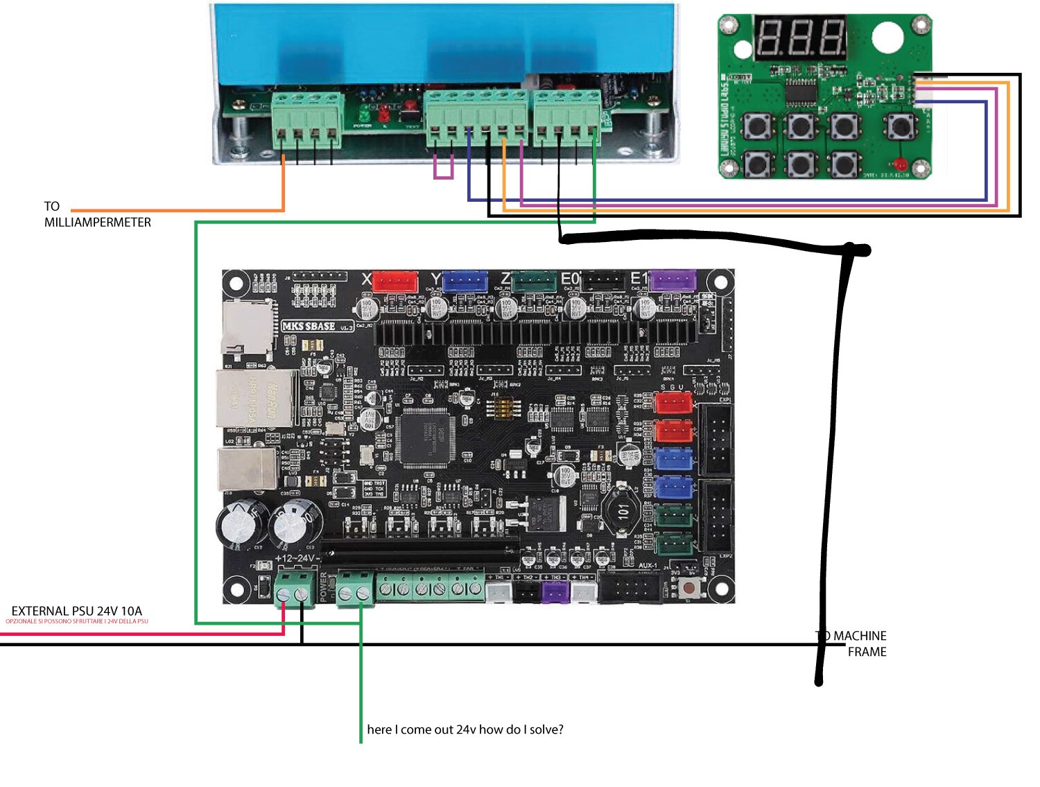
Just connect the - pin of the bed output to the L pin of the LPS (like on your schematics) AND ALSO connect GND of the board to GND on the LPS.
You can not measure the voltage on the - pin against GND, because this pin is floating when PWM is off and pulling to GND when the PWM is on. If you measure the voltage between the two pins of the bed output, you will get 24V when PWM is on and 0V when PWM is off, but the Voltage doesn’t matter, because the + pin is not used!
Think of it like the + pin is directly connected to 24V input and the - pin is connected through a switch (MOSFET) to GND. So the - pin connects the L pin of the LPS to GND when PWM is on, which activates the OptoCoupler in the LPS.
1 Like
Ah! The led diode (D14’s) anode [see schematic above] is connected to 24V.
Therefore when Q4 is off its drain will read close to the 24V bus.
This LED just shows the on-off state of the Q4 switch.
It should have no effect on the connection to the LPS.
If you are concerned about it unsolder one leg of D14 or remove it.
It looks like the (-) pin is the DRAIN connection. We still need to verify.
Are these really negative (-) voltages they should not be?
Is this a measurement error with the DVM leads reversed?
With the power off you can see if the (+) HOTBED pin is connected to the +24 on the input connector labeled POWER. The POWER connector is to the left of the hotbed connector.
With the 24v power unplugged from the board measure the resistance between the pins
+POWER and +HOTBED.
If they are connected the resistance should be close to 0 ohms.
Post the results.
If the +POWER and +HOTBED are connected then via the process of elimination the other pin -HOTBED is Q4’s drain.
Make sure the LPS ground is connected to a GND on the controller board. DO NOT connect the +HOTBED to anything.
1 Like
@cprezzi thanks tomorrow I’ll try and update you thanks to you too @donkjr I’ll keep you updated too
I was not sure if the -Hotend was the drain. there is no pin # on the layout :)!