Good morning.
I have installed a FluidNC board and running Lightburn.
When I power up I get the message : Limit Switch tripped for X&Y motors.
I do not have mechanical trip switches so I assume the laser is fitted with electronic trip switches
I have spent ages checking the wiring as per Avataar website.
I am having no luck and would appreciate it if a forum member could possible throw some light on the problem.
I could not find a specific topic in the forum so I hope this is the correct way to post.
Thanks
Alex
From the above, I am guessing this is your configuration.
Machine: K40
Controller: K40 FluidNC Shield (v8.xx)
Software: Lightburn
Q1: Is the above your configuration?
Action #1: Post pictures showing as much wiring as posible;
- Your endstops
- Your control panel
- Your controller
Background Info:

Controls & Limits connector (Red) on your K40 FluidNC Shield :
- If you have a K40 with ribbon cable, the limit switches are already connected via this cable for the X and Y axes → no need to connect anything to the limX and limY pins
- If your K40 does not have a ribbon cable, you will have to connect the limit switches to the LimX and LimY inputs
- If they are mechanical contactors, it is not necessary to pay attention to the wiring direction.
- If they are digital contactors (optical or capacitive), you must pay attention to the connections. The signal cable should go to the row furthest inside the board, the ground cable to the row furthest outside the board.
- If you have a motorized bed, connect the limit switch of this bed to the LimZ
- If you wish, you can wire buttons/sensors to the inputs:
- Hold: allows to pause a job (the laser is turned off, but the air assist remains active)
- Start : Allows to resume an interrupted work
- Door: If this sensor is activated, the machine will stop and the air assist will stop. Resume possible by pressing the start button
- Reset : to restart the ESP 32 and the K40 FluidNC shield

Hello Don
Thank you for responding so quickly. It is appreciated
Q1 Yes
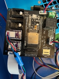
Images are attached
Have a ribbon cable
No motorised bed
Not sure about wiring/buttons sensors
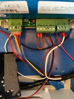
Notes on the wiring:
Laser Management.You will see that I have used red/blue/green /black configuration I have double checked the connections to the power supply
The red to connection 3 the blue to the left
Green not used
Black to the right
I have installed new stepper motors: Nema 17 with .9 steps
New stepper drivers DRV8825
New ESP 32 chip
New power supply
All this was probably not necessary but it has been trial and error
The wires into the power supply have ends soldered for a good connection
I have tested power supply outputs and they read correctly 24v and 5v
Thanks once again
Regards
Al;ex
Is this the problem you are having?
If so:
Action #2: Unplug the white ribbon cable (the yellow outline) going to the controller.
Does the error still occur when you power up?
What exactly is the error text?
Have you found any schematics for this board?
More background info:
http://wiki.fluidnc.com/en/config/homing_and_limit_switches
Not being familiar with K series machines, does the ribbon connector have the limit switch lines in it?
If nor, all bets are off because the 8825 drivers do not do stall detect and cannot be homed with it.
And even if that cable does have them, are they connected and configured properly on the board.
If they are present and wired correctly then this may be as simple as inverting the switch polarity in the config.
Yes, the optical sensor switches are in the white flat cable.
I was hoping for a schematic to see how they are connected on the board.
The optical sensors also need to be powered correctly.
I also wondered about the config but figured since this thing is built for a K40 it would have the correct config with it. Best to check.
I was hoping that the same signals that came into the Yellow outline connector also was duplicated at the red outline connector so we should measure the output of the sensor.
Just remembered,
It’s pretty common for the optical sensor interposers to get bent and then damage the sensor as it enters.
Post a picture of each of these sensors so we can check.
Thanks Don
I will post photo as corrected. I have examined the optical switches. The metal tang for each axis passes through and does not touch the sides of the limit switches.
Another problem I am trying to do sort out is the connection of the stepper motors wiring.
The Nema motors have 4 wires. Red, Blue, Green and Black.
Red and blue are a pair.
The FluidNC board for the X axis has a ribbon cable . On the small board where the ribbon cable controlling the X axis is fixed a 4 pin connector is taken off to power the X motor.
The main board for the Y axis also has a 4 pin connector.
The . The problem I have is what order the motor wires have to be connected to the pins,
Unfortunately there is no indication of this on the controller.
I am sorry this is so long winded but I hope this makes sense to you.
Thanks once again.
1 Like
I am lost with reference to a small board, large board ribbon cable etc.
Post pictures pointing to what you are referring to.
Schematic of K40 end stop wiring for reference:
Thanks. I have now resolved the wiring issue of the stepper motors, got the sequence correct. The little “board” to which the X axis plugs into is the same where the ribbon cable connects. Not sure of the technical name.
Exactly what is left to fix?
I keep getting an error message “Homing cycles not defined” I am trying to get my head around this.
When opening Machine Settings I get the message that it has been read successfully but the page is blank so I cannot check anything there.
I suppose one step at a time.
Lightburn does not know about FluidNC grbl-ish settings so you won’t be able to use Lightburn to change or view the settings. That will have to be done either with the web page of the FluidNC esp32 or via the Lightburn terminal interface.
Lightburn supports only the default GRBL settings and strictly validates to it. I ran into this when I put GRBL-HAL on a cheap diode laser board(STM32 based).
Thanks .I am in the process of trying to hook up with wifi.
FluidNC provides strong backwards compatibility to the ‘old’ grbl $xx options, but by default doesn’t fully report them in response to $$ queries (you only see the $10 (machine vs workspace position reporting setting), which can confuse lightburn, ugs et al.
The FluidNC documentation is an essential, nee, mandatory read here. There are no compile time options. It is a unified binary. Every setting you need (pin def’s, timings, probing, homing, everything…) is available via the terminal/web console. And a config file is used to load the defaults at boot time.
3 Likes
Unfortunately this is much of a rant but I need to get it off my chest.
FluidNC board with Lightburn.
I have now spent over a month trying to get my K40 working
I keep getting the error “homing Cycles not defined”
I have searched the web for an answer but nothing on this topic.
I have replaced the power pack, the stepper motors, the drivers on the Fluid board as well as the esp32 module.
I have put a request on the FluidNC web page but have received no response
I am now wondering whether it is a board problem or a corruption in Grbl on the board.
Trying to update firmware following the Fluid website in instructions do not work. I input my ip address and Github comes up.
I now think it may be time to ditch this board and install a Monoport controller.
Enough said. Sorry!
Did you go step by step through this setup and testing document?
http://wiki.fluidnc.com/en/config/homing_and_limit_switches
It would have indicated that your limit switches were configured correctly or not and if electrically connected correctly or not. Then it would be a matter of enabling the homing cycle settings in the configuration file so that the motors move in the correct direction when the home command is sent( $H ). Remember, the home command is different than the G28 command which is really just a shorter version of G0 X0 Y0 Z0 command. ie G28 goes to zero positions while $H commands it to establish where the zero positions are by moving the axis motors and triggering the limit switches.
FWIW, when installing new boards in 3D printers, laser engravers/cutters, CNCs, etc I’ve found the following a good process:
- Recheck your power connections and verify your voltages are as expected(requires a volt meter)
- On power up, be prepared to turn your machine off if the motors start to move.
- Power up and watch each axis to be sure the movement is towards the axis endstop but power off before an endstop is reached. If not, change homing direction in the firmware or config file.
- Power up and manually trigger the X axis endstop and notice if X motor stops moving. If not, recheck wiring of the endstop and recheck configuration of the endstop in firmware or config file.
- Do the same for the Y axis after the X axis movement is stopped by manually triggering endstop
- Power up and let the machine head trigger the endstops and observe no grinding. Adjust soft-endstops and backing off distances in firmware or configuration file. 2-4mm is often enough.
- After a completed homing cycle, test motion of moving the X axis 10 mm( use GUI ) then test moving the Y axis 10 mm. if the distances are not correct, adjust the setps-per-mm setting in the firmware or configuration file for each axis. Retest.
- Test the outer limits of your machine by stepping towards the full motion edge of the machine to find your “operating” area. There should be no grinding and every command must result in the expected motion. Note how far you commanded it to go and adjust your firmware or config for that axis max limit. Store these values somewhere so you remember them as you will likely require them in any CAM software to specify your working area.
- The motion control system should be mostly configured at this point. Test the spindle operation, or laser operation, or whatever else the machine is supposed to do.
2 Likes
I don’t feel like this error is related to bad sensor inputs …
but when stuck… try more stuff!
Have you read the sensor inputs? If I recall there is a way to read these from the controller interface?
BTW:
This is why I do not use controllers that do not have complete documentation [schematics], and an active forum monitored by the board maker.
At a quick glance, Monoport:
- Does not provide schematics
- Does not support the white ribbon cable which means you may have to rewire the endstops which is a challenge unless you add a middleman board.
1 Like