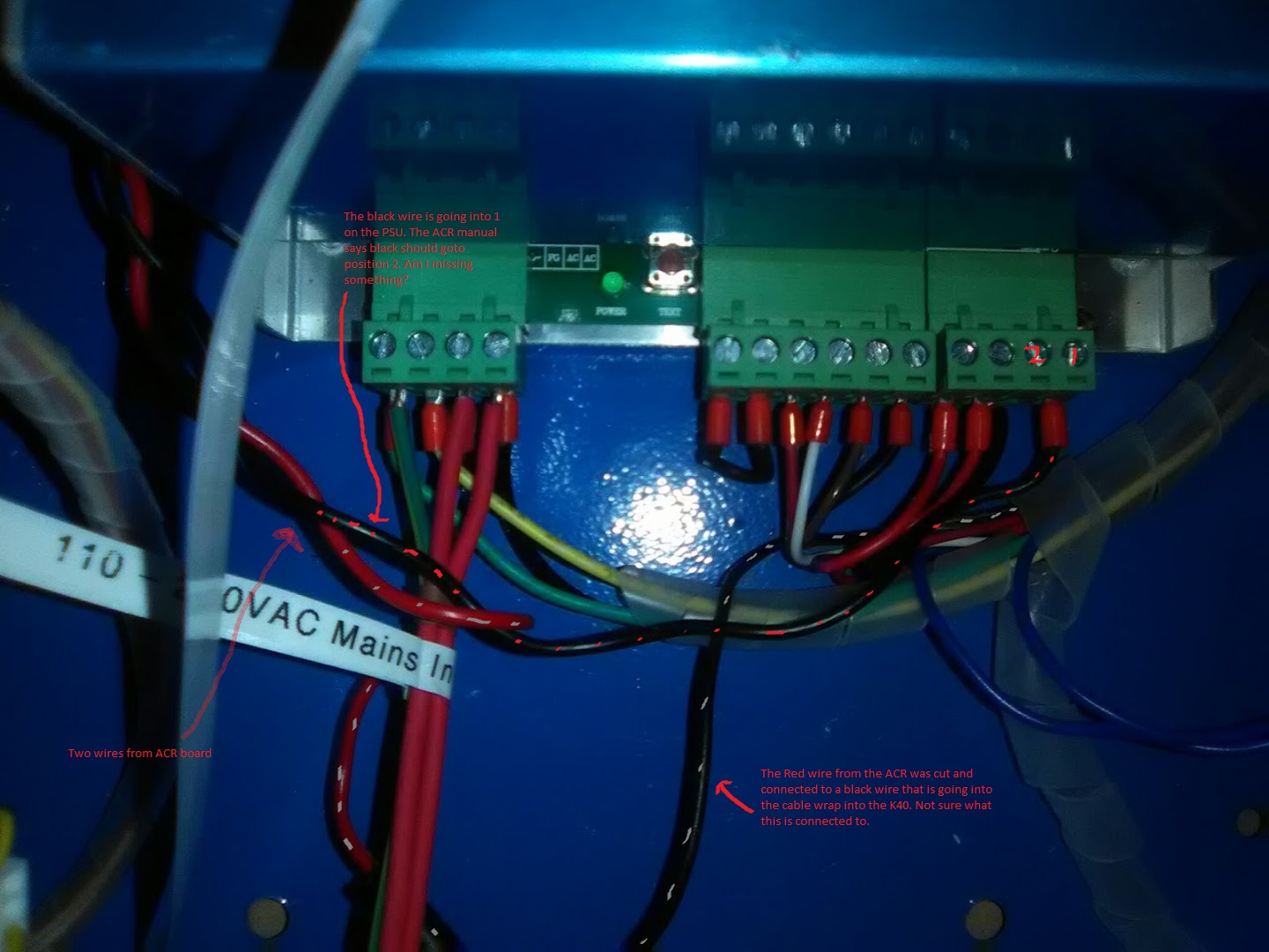
There was probably a wiring mistake made for sure. Keep in mind Scott had not worked with this power supply before. He was also telling me what wire to put where over the phone and could not see what was happening. A lot of room for error for sure. Here is a screenshot from Scotts ACR manual as well as a picture of how my ACR is wired right now. Can someone look at this and verify that the black wire from the ACR should go into position 2 on the PSU?

I just got my ACR from Scott running this week. What I found was that it was miswired - if you follow the wires from the M1 output of the Smoothieboard they were plugged into the Y inputs of the ACR board, and X was plugged into M2. My K40 didn’t have the flat cable, so I was using the individual connectors to plug the stepper motors in to. I know the ACR is meant to be a plug and play solution, but it appears some wiring accidents are happening. I would recommend checking with a continuity meter each connection from the Smoothieboard to the ACR to make sure it goes where you think it should - the ACR connections are labeled so this is easy to do. I wonder if you’re using the flat cable and the connections are reversed, so you’ve basically got two drivers driving the same connector - that would kill things pretty fast if true, so check ASAP. The X and Y motion wasn’t what I expected at first, the X moved backwards and Y seemed strange. I reversed the X motor by swapping the polarity of one of the coils on the input to the ACR board - I liked the idea of doing it there instead of a software config change. The Y axis takes getting used to - the homing switches are at X=0, Y=MAX, so Y- is towards the front of the machine, so when you’re getting started this is confusing because when you do a manual jog in the Y- direction it moves forward, but then when you kick off a home it moves in the other direction - this is actually correct.
Aside from the laser not firing…the X and Y homing and movement is great as long as I plug the motor cable into the X connection on the ACR and not the Y connection.
I’m just wondering if the black wire from the ACR simply goes into position 2 instead of 1 on the far right connector on the PSU to resolve the laser issue as in my photo above.
I figured I’d fix it once early on and then all the labels on the board would be correct and easier to figure out in the future. I’m not sure if having the X connected to the M2 output of the Smoothieboard would cause other weirdness I hadn’t gotten to yet.
@Carle_Bounds
that would connect the ACR output to 5VDC so I would not do that!
The LPS DC connector is as such:
Starting from the right going left:
L
5VDC
Gnd
24VDC
I don’t know what the black wire from the ACR is?
OK thanks Don. I won’t do that…
I just saw the instructions that you posted. The pin descriptions are from left to right and suggests:
Black to pin 2 that is grnd
Red to pin 4 that is “L”
So if you are wired like this you are correct.
What is in the config file for your PWM?
@Carle_Bounds I am pretty lost at this point cause I am not certain how you have the PWM wired now.
It seems to me that when the laser was on all the time the PWM polarity was backward. Did you try changing it in the config file.
The config up above has the PWM inverted but that may be correct for use with a level shifter however not for the schema I sent you.
@Steve_Prior how is your smoothie to ACR and then ACR to LPS wired and what is the PWM set to in the config.
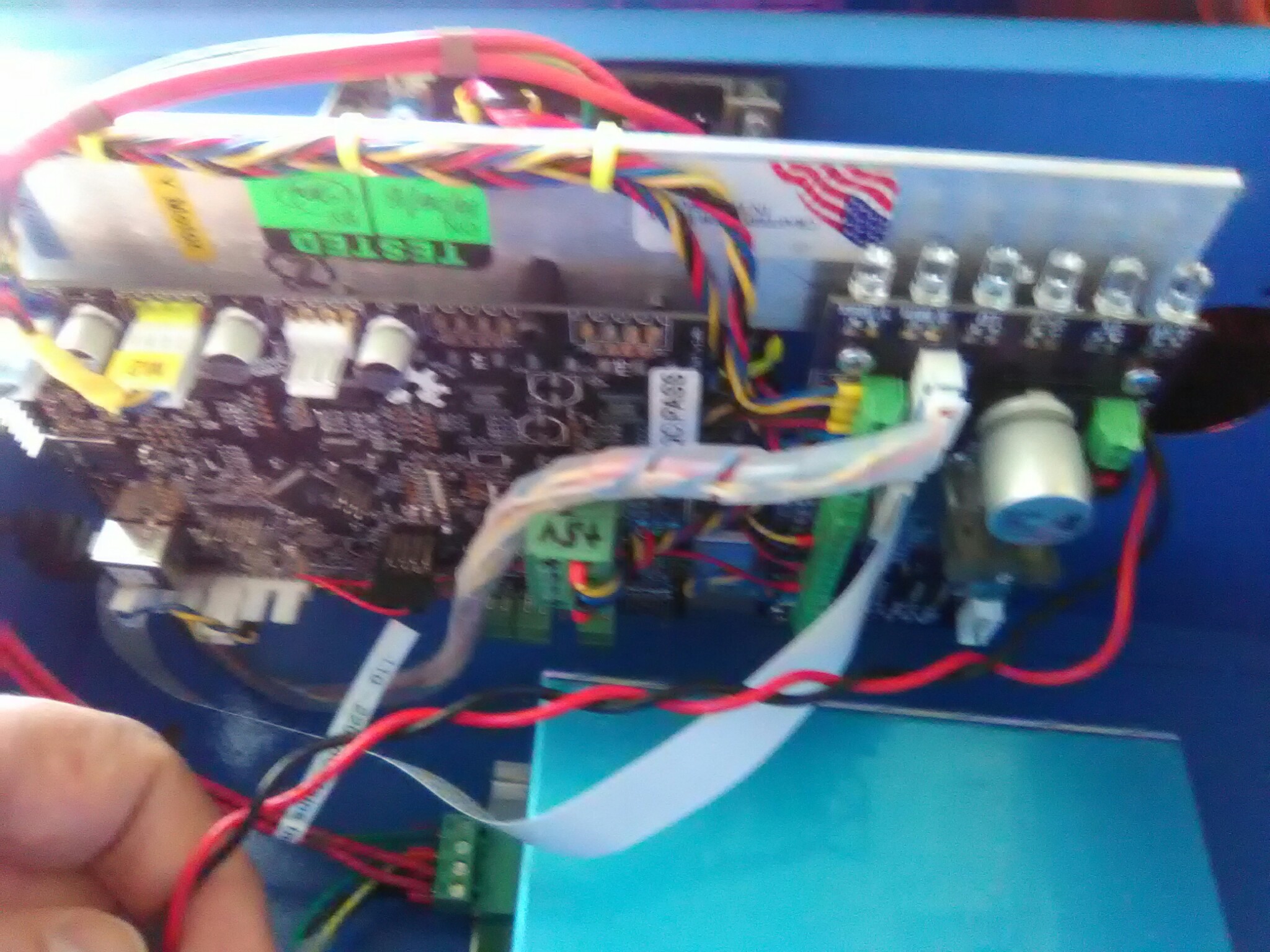
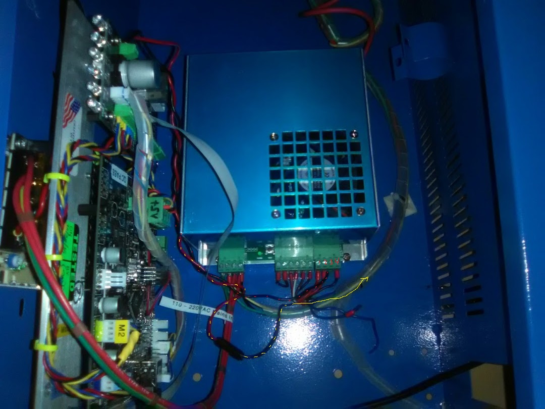
I have not edited the config file. FYi…Also this is the full acr plug and play board with an additional power supply to take some load off the k40 PSU.
@donkjr take a look at this picture please. The black wire from the ACR is going to pin 2 which is what you were thinking should be right but… the red cable is spliced to another cable going up into the K40 cable wrap and not into pin 4… This could be the mistake right?
@donkjr I have not changed the config at all from what Scott provides. My laser is the simpler one with the analog power knob, and I’ve got a “white connector” power supply. My wiring is exactly what’s in the instructions. The only things I have changed were the wires between the Smoothieboard and ACR boards - I corrected the swap of X and Y so now M1 is connected to the labeled X inputs on the ACR. I also swapped one coil on the X input of the ACR to correct the X direction of travel. Firing the laser works, though I don’t know for sure yet PWM is working (I think it is) since I’m just getting familiar with LaserWeb3.
@Steve_Prior so your red wire from the acr is going to L pin 4 on the PSU correct? And the black wire from the PSU to pin 2 gnd of the PSU?
@Carle_Bounds in regard to the black and red wire I think the answer is yes but I do not know where the other end of the red wire goes (or I don’t remember). Nor the black.
I cant see any of the connections on the ACR.
Can we used the name of the connections on the ACR as well as the wire colors to identify stuff.
Perhaps multiple pictures taken perpendicular to the controller.
@donkjr the other end of the red and black wire are already connected to the acr. Scott shipped the acr with the black and red wires connected on the acr