Well changing the laserweb settings to pwm 1 instead of 256 for smoothieboard did not resolve issue. Turning the ribbon cable around didnt work either. I tried moving the motor connector back to the Y input but the motors acted strange again and it tried to home in the lower left hand corner. Put the connector back in X and it works fine. When I run jobs it moves correctly and I can see it trying to create the correct shapes but laser is not coming on still. Hmmmmmm
Did you try the laser on off commands as G0 and G1
I created a macro button in laserweb from an article I found to create a test fire button in laserweb3. The code I used is:
G1 Z1 F600 S0.1
is that correct? It doesn’t fire with the macro
Yes I set the laser off to g0 and laser on to g1. Also in my post above you see I tried a macro to make it fire with g1
I’ll double-check your config file when I get home
Man thanks so much!
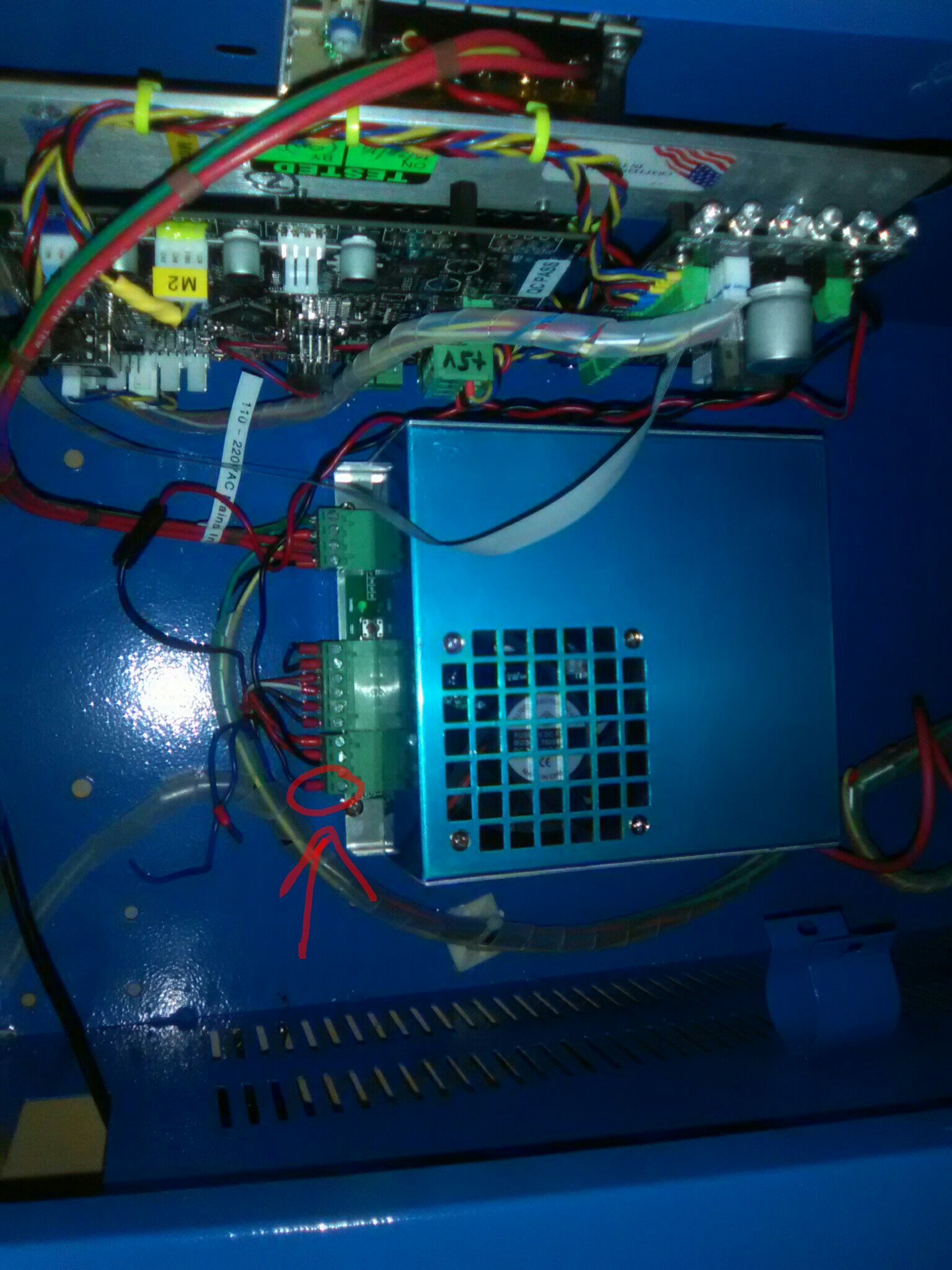
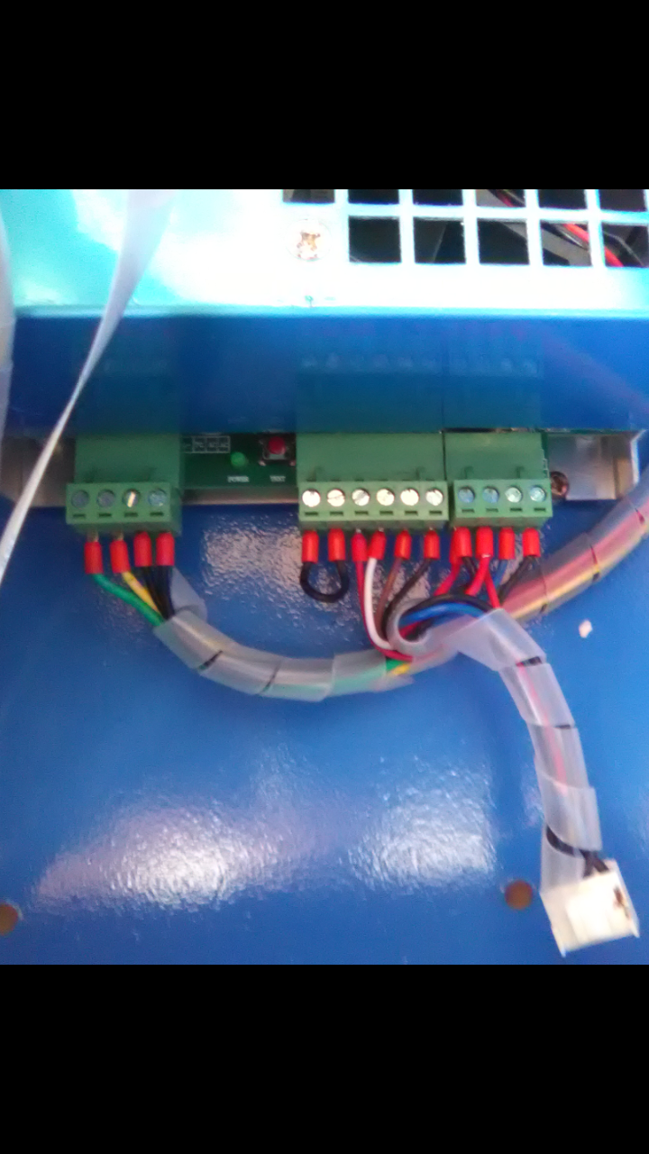
looked the config over it looks good assuming you are connected to the pin in the middle of the smoothie board for the laser. did your machine come with the ribbon cable connected to the m2nano board, If it did then the ribbon cable is for the Xaxis motor and the end stops and the Y axis motor will use the four pin cable with the white connector. could you post a picture of your entire wiring setup? so we can see where the wires are running from the board to the PSU
Scott usually puts either a 2 or 3 amp automotive type fuse on his boards. If I remember correctly x and y will move but laser will not fire if that fuse blows. Test fire will still work.

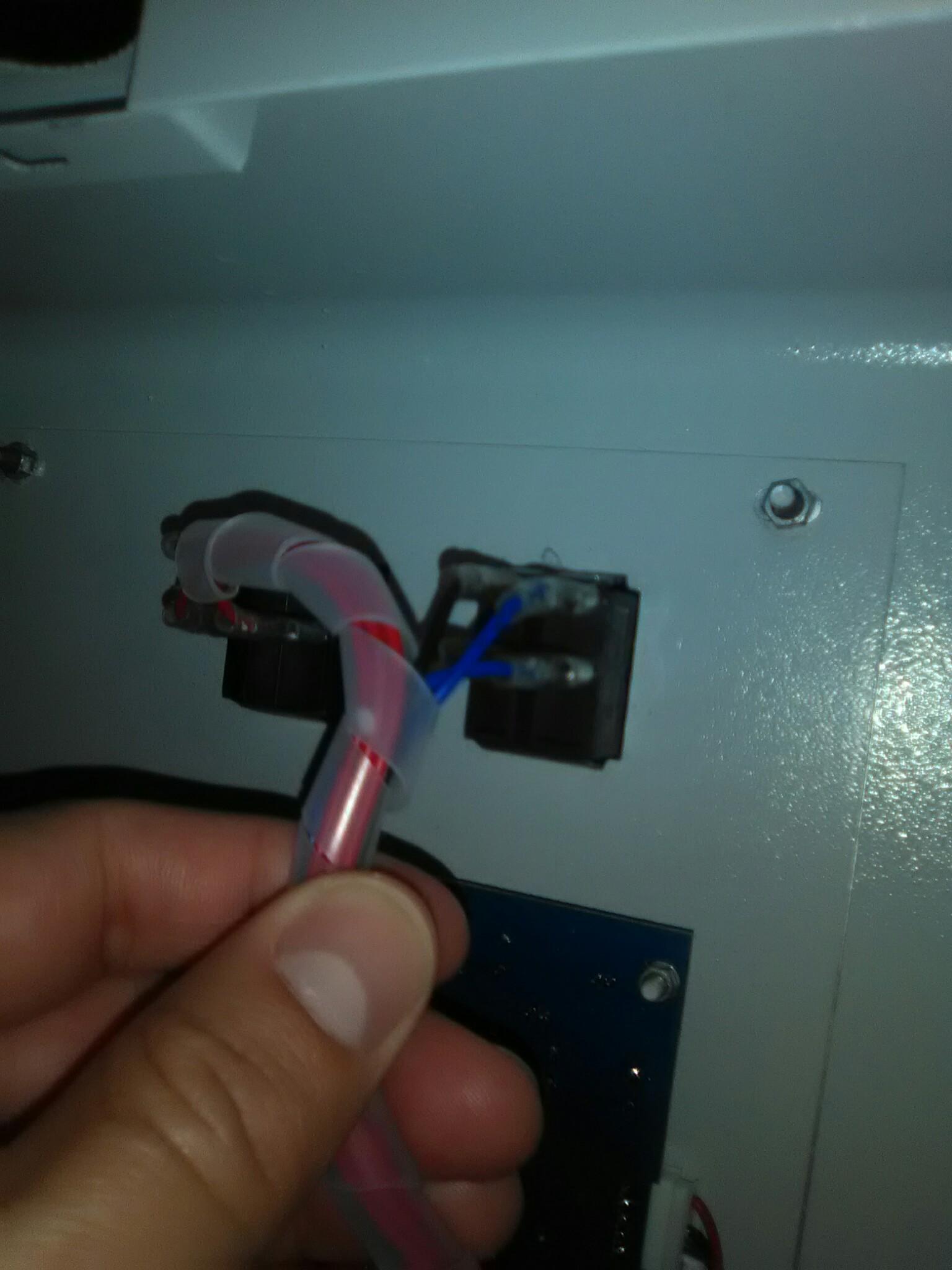
The two blue wires you see not attached goto that red toggle switch on the front. Scott said that was used to turn the old k40 board of and on and was not needed as the black switch next to the emergency stop button powered the whole k40. He said I could use the red toggle for something else later. Just wanted to say why those wires are not attached.
I pulled out the automotive fuse and visually inspected it. The wire inside looks intact and it does not appear blown. Thanks though!
I’m pretty sure that’s the wire you need to connect to the laser fire connection on the board… let’s have @donkjr verify, he has done extensive research on the psu’s

@Alex_Krause @Carle_Bounds
It looks to me like the PWM from smoothie is not connected to the LPS. Its hard to tell from the picture.
There should be wires from the smoothie to the LPS somewhere, likely the “L” pin on the rightmost LPS connector. The one that @Alex_Krause suggests is open.
I am not familiar with Scott’s setup but I would guess that something (PWM) is supposed to be wired to the “L” pin which is the rightmost pin on the rightmost LPS connector.
From the picture on his site I see that there is a yellow and green wire coming from the pins that are the typical PWM pins to Scotts board. I do not know where they are supposed to exit his board and connect to the power supply however.
This is all my best guess…
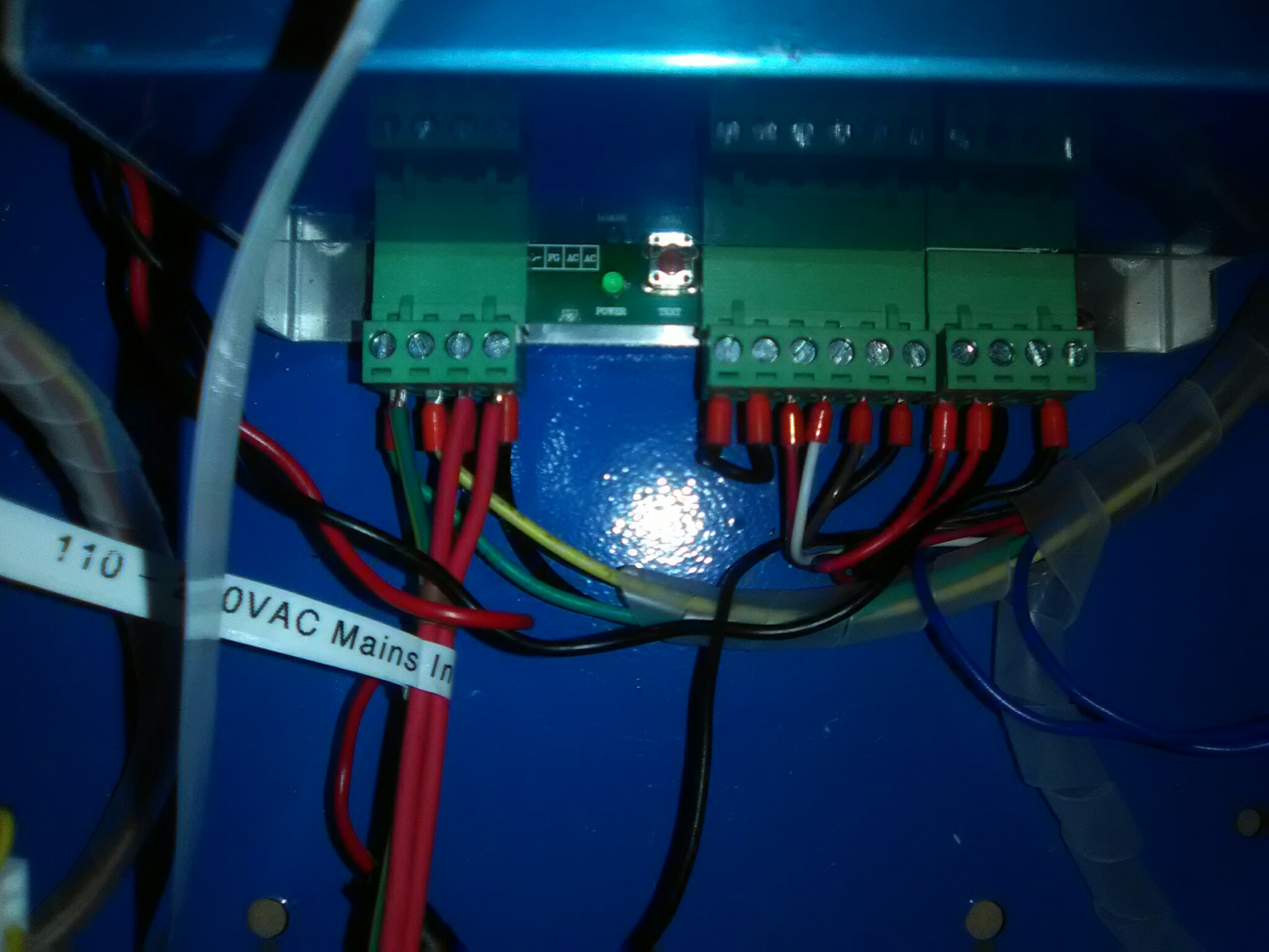
It looks like there should be a pair of wires from the smoothie to the “Fire” terminals on Scotts board. They are the green and yellow wires from the upper middle of the smoothie.

Then I think there should be a cable from the “LO” plug on Scotts board to the “L” pin on the LPS.
This picture shows both the “Fire” terminal on the right and the “LO” socket on the left.
