Here it is. Try not to laugh too hard.
Title.FCStd (152.2 KB)
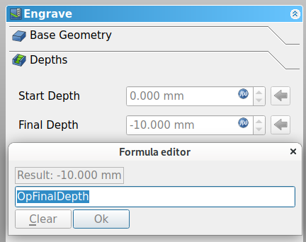
You can choose “Clear” and set it to, say, -2mm
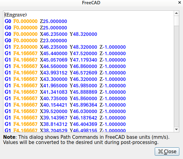
But I don’t know what you intended. It’s following the outline. it’s not doing a variable-depth v-carve; it’s just tracing the outline of the font at the selected depth.
You can change to “Use existing solid” and select the sign body. That way, when you run the simulator using the Path_Simulator button or typing the “PM” shortcut, you won’t have stock obscuring what is happening.
Watch the bit as it traces out the lines.
Select just the Engrave OP and then the Path_Inspect button (“PI” shortcut) and you’ll see that your selected Z is chosen. For example, I set it to -1, and get this:
Sliptonic works on the Path workbench:
Do you maybe want Path → VCarve instead? I have never used it, but maybe this video from when it was in development will be useful for seeing how he set it up three years ago when he was developing it?
")
Actually, read this wiki page: Path Vcarve - FreeCAD Documentation
A limitation of Path_Vcarve (for the moment, at least) is that each face has to be a separate operation. By selecting one face at a time, I can add individual ops for each face (some letters have more than one disconnected face) and it seems to simulate fine at least as far as I went. Edit: Actually, some of the letters don’t seem to carve. This might be worth reporting on the FreeCAD forum — their bug reporting process is rather unusual; they won’t take a bug report without a forum conversation first, mainly because most reported bugs were not actually bugs and it’s how they filter out the misunderstandings.
It’s a bit inconvenient to select every face and add a Vcarve op for each one but here’s where that got me:
TitleVCarve.FCStd (172.0 KB)
But I’m not sure what your intent is with the overlap between letters, and I could see it looking weird when carved even if that all works right?
@Scorch wrote an engraving tool called F-Engrave that might be easier to use right now for that specific job of v-carving text.
Where’s the “clear” button? How do you get to that formula editor? When I choose “Depths”, I get a display with the depths grayed out, and I cannot change them. This is BTW Freecad 0.20. As to “what I’m trying to do” - just trying to get to know the tools. I plan to mess around first with the simulator, then with scraps of plywood or MDF.
You can either click on the round blue f(x) button at the right end of the entry box, or just type = — there, you can type your own equations, or just clear it to make it no longer an equation.
(I’d been using FreeCAD for a while before I learned SolidWorks and got into the habit of using = there to bring up the equation editor, I accidentally did it in FreeCAD and learned that it was an easy way to bring up the equation editor and was so happy to be liberated from the mouse!)
Sure, but even then I presume you have an idea what result you were expecting as you experiment. That was really what I was asking about.
Anyway, I’m pretty sure that I was wrong, Path_Vcarve should work on the Draft ShapeString you used for the text as a single object. I just didn’t read the documentation clearly enough, and didn’t understand what I saw. I think it’s having trouble with some of the shapes in that string. I’ll bet it would work fine with some other font.
I’ve confirmed that switching the font to LiberationMono-Bold (much simpler shapes) makes the Path_Vcarve operation work. This might just be a bug, and I’m going to bring this to the FreeCAD forum. I have simplified the pad to remove the hole so it’s not a distraction from the problem.
I deleted the file and started over. And this time, it just worked. First I tried with a simpler “block print” font. Got a nice big G-code file. Then tried the fancy font again…another big G-code file. Your hint about deleting each “formula” and typing in a number for the depths worked fine.
Now to see what the machine does with it.
Ultimately, I’d like to mill the entire front panel - including the big hole for the display, holes for mounting screws, holes for buttons, switches and lights.
The display hole is especially challenging; since it’s a touch screen, the edges need to be beveled. And it needs four mounting holes which must be located very precisely in relation to the screen surface.
I milled the existing one on my Sherline ( not-CNC ) mill.
Yesterday, an annoyance of modern life; I had ordered a replacement GRBL card on Ebay. Yesterday,
UPS delivered it. Or they say they did. There is no package. Luckily, replacing the transistor worked on the existing board.
A chamfer is easy to add in the model. Do you have a 45° v-mill to cut it?
If you have a STEP file for the mounting holes, you can import it, translate it, and use it as an external reference for the holes you are cutting.
I beveled the edges with a countersink - made for beveling screw holes. Chucked in my Sherline, it worked fine. Probably not as sharp as a real v-mill though.
My countersinks that I originally bought for use with wood now live by my mill for use in aluminum and have been used for chamfering. ![]()
GMTA ( Great Minds Think Alike ) :).
The new controller did arrive. Although the shipping said “UPS”, it surfaced at our USPS cluster box unit.
The router is now routing. It’s putting my fancy title onto a scrap of plywood.
It did engrave my fancy title - on the piece of scrap plywood. Came out somewhat messy - that plywood just wasn’t hard enough to support such intricate shapes. Trying again now with a piece of oak. I have set it to engrave multiple passes, 0.2 mm deep per pass, aiming at a total depth of 1.0 mm.
I fastened my oak with the “two-masking-tapes-and-superglue” technique.
I’ve learned that it’s important to set the zero position properly. Lest I watch helplessly while the machine tries to set the Z axis zero in the middle of the wood somewhere. Abort!
Besides the fancy title, I need it to put switch and connector functions in the appropriate places - in simple block print.
Late to the party. $30 is the spindle rpm, in reality the range used for the PWM algorithm (on % is requested over max, no hyperdrive so anything over the max gets 100%. Yours is set to 1000, so 500 is 50%, etc.
Grbl’s source is on github, separate projects for the very old obsolete 0.9, and the 2016 (first release, 12/9/16 so it was created before that) to now 1.1. I imagine there’s a way to coax the project creation date out of github, but it wasn’t obvious to casual inspection. There’s also a wiki that’s worth reading. Today I’d be looking at FluidNC on an ESP32 instead of the 328P version of grbl, but that’s just me. Bart Dring has a baseboard that takes plug-in interface modules on Tindie, I’m playing around with the far cheaper WeMos board and an Uno CNC shield V3
Many of those 500W/48V spindles have a potentiometer for speed control, which supplies a variable voltage to the supply/controller that controls a PWM output. Some will mention Mach3 control and/or 0-10V, otherwise put a meter across the pot. Pretty easy to find PWM to variable voltage convertors including 0-5 and 0-10. If you have one then there’s no need to have created separate circuitry to do the same thing. I’d look for a board with an optical isolated input, just connect that to the 24V (or whatever) PWM output from the grbl board, and then to the “Mach3” or potentiometer inputs if they’re an appropriate voltage. Plenty of boards (as always read specs and see if it at least pretends to be what you want) on Amazon in the states, AliExpress if you can wait for somebody to paddle it on a raft to get it to you.
The idea behind $30 is to set the max spindle rpm which is then converted to 100% PWM. This way you could set the rpm with the S parameter, instead of just 0-100% (but it’s not very linear).
PS: This board seems to be based on grblHAL (because $38 was added by grblHAL).
see: grblHAL/settings.md at master · terjeio/grblHAL · GitHub
Thanks for all. I found out that I need