I can’t recommend enough Joko Engineering tutorials for FreeCAD. He, IMO, is the Bob Ross of CAD tutorials. ex: FreeCAD: The 2022 Complete Beginners Guide To Part Design |JOKO ENGINEERING| - YouTube
1 Like
Joko is great!
One more source of good recent FreeCAD videos is:
Also, for working with Realthunder’s LinkStage3 branch, see:
1 Like
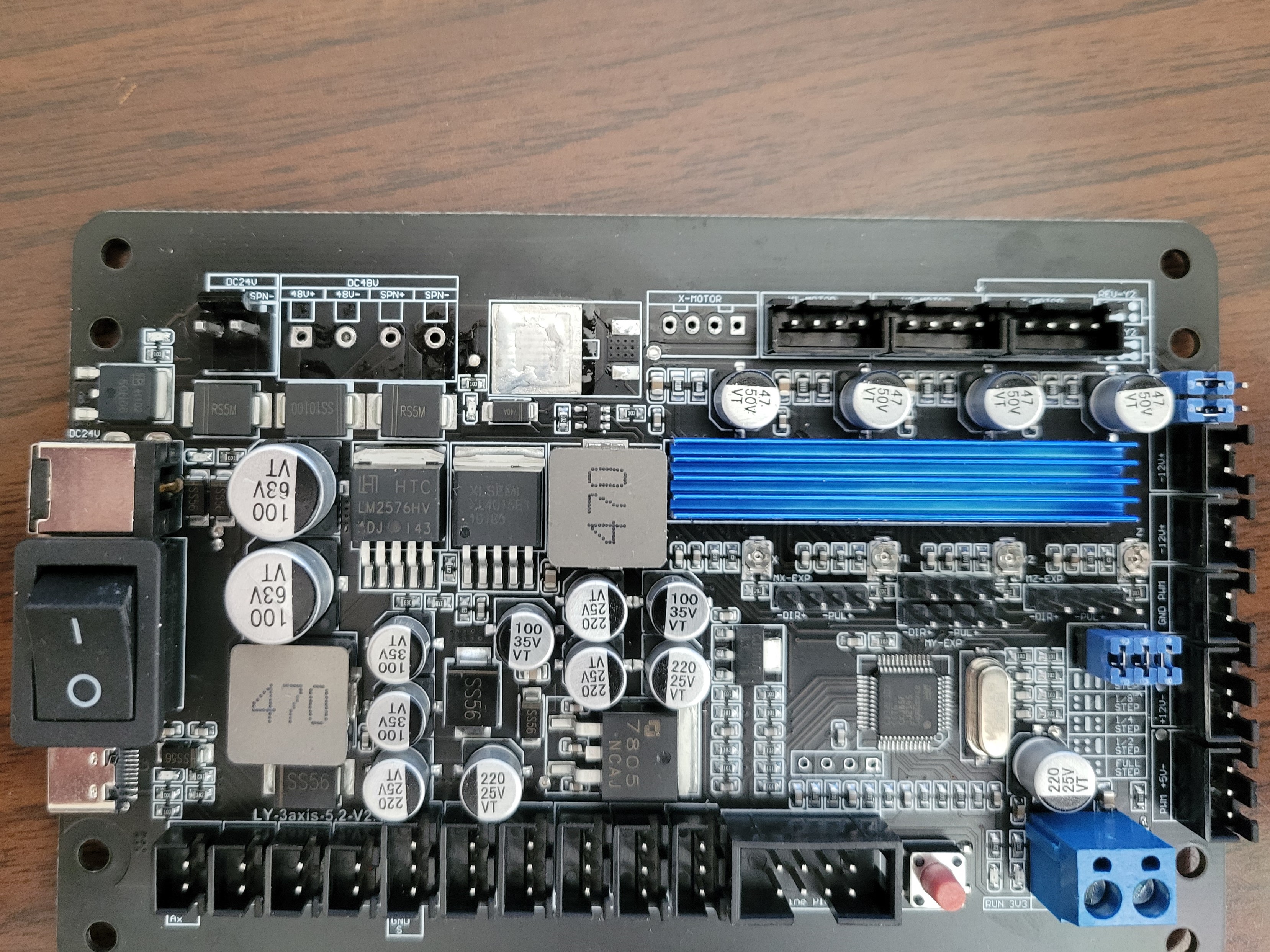
So I took a break from busting my brain with Freecad. Went out to the garage and pulled the misfunctioning circuit board off the router. Sat down to unsolder the offending transistor. I was worried about the plastic connectors getting melted in the hot air, so I desoldered them first.
BTW, if you need to desolder thru-hole parts, the ultimate tool is the “Yihua 929D-V”. It’s basically a solder sucker with a heated tip.
Then I cranked my hot air rework station up to 380C. Desoldered each pin separately. Then heated up the body of the transistor for about 20 seconds and tweezed it right off the board.
A quick check with an ohmmeter verified that the FET was shorted out. Interestingly, not only the drain-source but also the drain-gate.
If I didn’t know that new parts were arriving tomorrow, I’d be tempted to just tack in an IRF510 and see what happens :).
Thinking about PWM speed - I’m wondering what’s the base frequency of the PWM. Considering that the MOSFET has no heatsink, I’d expect the frequency to be fairly low, because otherwise the device will spend too much of its time in transitions ( between on & off ) and it would burn up. But if it’s too slow, the motor will be jerking round & round. Maybe I’ll stick an oscilloscope on it.
OK, back to FreeCAD. I think that engraving and other “subtractive” operations are conceptually more complex than pure additive stuff aka 3D printing. You have to choose a plane that the machine will engrave, and I’m not sure about the Z stuff - choose somehow a shape and “bind” the milling “Job” to it.
1 Like
Can you provide a complete $$ output from that board?
$$? Only after I reinstall it. BTW, there is a protection diode across the spindle motor output. It’s forward voltage is only .436 - maybe it’s a Schottky.
I would think that it would be ok to just connect it to USB and check?
Sure sounds like it!
Grbl 1.1f [‘$’ for help]
$0=10
$1=25
$2=0
$3=6
$4=0
$5=0
$6=0
$10=3
$11=0.010
$12=0.002
$13=0
$20=0
$21=1
$22=1
$23=7
$24=25.000
$25=500.000
$26=250
$27=2.000
$30=1000
$31=0
$32=0
$38=10
$100=800.000
$101=800.000
$102=800.000
$110=2000.000
$111=2000.000
$112=100.000
$120=20.000
$121=20.000
$122=20.000
$130=500.000
$131=500.000
$132=200.000
ok
Scope measurements: The PWM is 10 kHz.
At “S 500” I see about 50% duty cycle. at “S 800” about 20 percent duty cycle. at “S 900” about
15% duty cycle.
It looks like the useful range is about “S 0” to “S 1000”.
Wondered what CPU this had; @cprezzi made the LPC variant take a $33 parameter to choose the PWM frequency.
They probably didn’t change the default; this issue should show where to look:
Here’s the line that sets it in the code to about 1kHz (actually 0.98kHz) by default:
You can set it to 1.96kHz, 7.8kHz, or 62.5kHz instead by choosing which line to uncomment there.
I have no idea what that really means in terms of RPM.
Huh, 10kHz I guess I was wrong. Do they provide source code? Grbl is GPL so they are obliged to.
Back when @Brandon_Satterfield was selling hardware, he used a tach to characterize the spindle speed curve for each type of spindle he sold.
a tach: I am tempted to do just that.
1 Like
The posted schematic (post 16) show a ss54 on the spindle and another one on the laser pwm drive.
"“SS54 is a surface mount High Power Schottky Rectifier with a Low voltage drop 0.55V and a high forward current of 5A.”
My Woodpecker ran at 1mS for the pwm period. I didn’t think the Arduino was capable of a faster pwm…
![]()
1 Like
It’s not an Arduino. As close as I can read on the top of the chip, it’s a GigaDevice GD32F303. That’s an ARM Cortex M4 clocked at 120MHz. There are approximately 1 zillion variants offered by GigaDevice,
and I don’t know which one of those it is. Probably one of the lower end ones.
2 Likes
Definitely ask them for the source code, then; they owe it to you and it can answer a lot of questions…
It could be grblHAL with compatibility level 1. If it had been based on grbl-LPC it should have had $33.
I found a good PDF tutorial on using the freecad Sketcher. It was in the sig of a poster on the freecad user help forum.
https://owncloud.gwdg.de/index.php/s/eZisrfTTCCjDEd9/download
So I’ve been practicing with “constraints”. Do a line, constrain it. Do a box, constrain it. Delete. Do over again.
Whups, the doorbell just rang! Fedex! With transistors!
2 Likes
So I replaced the driver transistor, and the spindle motor function is restored. Trying to put together something to engrave. Right now, FreeCad is insisting on a 10mm depth… ![]()
I try to modify it in the engrave-depths fields and it does not take any change.
1 Like
Yeah, that sketcher doc is great!
A few years ago, I found the FreeCAD sketcher twitchy, but the only things I have found in SolidWorks better than the current FreeCAD sketching are that in SolidWorks every line automatically has a midpoint (though the symmetric constraint in FreeCAD is almost always more useful) and the ability to do 3D sketches (which FreeCAD just doesn’t have).
Want to upload the example FCStd file for the 10mm depth question?
I had tried FreeCAD years ago and could not wrap my head around it. I found OpenSCAD a breeze so that’s what I used for many years. Then Covid and a guy in a woodworking group offered to do weekly CAD tutorials over Zoom and it happened that Fusion 360 would finally run in WINE so I started doing his classes and learned a bunch about 2D sketching and using a GUI for extrusion, boolean ops and selecting faces and edges to work off or manipulate. Was cool until AutoDesk jacked the licensing, kept changing the code so it was not backward compatible at the file level when sub-sub version was changed(ex: v 1.19.16 was not compatible with 1.19.10) and required upgrading.
That’s when I started looking at other options, read a lot of posts of people moving from F360 to FreeCAD, found some which were from a year earlier even. I reached out to 3 or 4 of these people and asked for their insights, issues and thoughts on such a migration and all of them said that FreeCAD became far far more usable with the 0.19 version and to get the beta since it was about to become a release. They were correct, with my 6 weeks of Fusion 360 CAD experience I was quickly able to make stuff in FreeCAD. Joko Engineering and others make learning about each area of interest much easier and love seeing what Michael has been doing.
I’ve not used FreeCAD toolpath generation though and only have used Kiri:Moto once I have the 3D model made in FreeCAD.
It’s really great having two good options here. FreeCAD has, I would say, more fine-grained control and a more complete tool library system. But when I had a complex curving object to route, Kiri:Moto was wonderfully simple and did a great job. Stewart does wonderful work there. Every time he fixes a bug I report, I read the code, and it’s usually simple and clear and often I learn something about JavaScript. ![]()
1 Like