I just purchased my second ( glutton for punishment ) 3018 router. The first one was a $105 Banggood deal that I simply could not resist. Of course, that one was pretty low end. Not very stiff, and not high power. I tried to engrave aluminum with it, and it barely scratched the surface.
This second one is at the $550 level. It’s a “3018-Pro” via AliExpress. It has a 500W spindle - and is clearly an order of magnitude stiffer than the cheap one. And limit switches! And a 40W laser. Which I might not actually use…seems really dangerous.
Took me about 4 hours to put it together. The mechanical parts were almost flawless. One of the sliding bars had a bad internal thread, and I had to fix it with a tap. And 8 screws were just a little too long, and I had to grind them down.
Alas the electronics were not as good as the mechanicals. The GRBL board died while I was messing with the spindle - just verifying that I could change its speed with the software commands, start & stop it, that sort of thing. Didn’t even have a chuck on it. The spindle motor came on full power and stayed that way, regardless of what commands I sent it. Or pressing the reset button. Only removing the power made it stop.
A peculiarity of the Chinese “high power” spindles - they work off 48V. Most GRBL boards are 24V max. And this particular motor does not have a PWM input - you vary its speed either by pulsing it, or by changing it’s supply voltage. Probably the former - linearly changing the supply voltage would generate a lot of heat on the board. Until it died, I was able to vary the speed with the S command.
There are not many GRBL boards that do 48V. I found an Ebay vendor that had the same board with USA stock and ordered it. I also messaged the AliExpress company - we’ll see if they honor their warranty - preferably withOUT me having to pack up the whole thing and send it to China. Honestly,
that ain’t happening.
If the Ebay board suffers a similar fate, I’ll have to give up on that, and go with a quality 24V board. Then I would need to build or buy some sort of external power regulator for the 500W spindle.
Smart to be wary of the laser. If you want to use it, I think @donkjr has a solution of putting a piece of plexiglass 2422 around the nozzle as an extra layer of safety in case, say, someone enters the room not wearing safety glasses. Also a good idea if you use it to not do it with loose dust that can easily catch fire.
Can you provide pictures / links for your failed board? If this board is directly providing power to the spindle, then the PWM control is built into the board; “pulsing it” is PWM, which stands for “Pulse Width Modulation”. The motor staying on all the time is probably the MOSFET on the board failing.
You can always just use an external PWM driver. They are available cheap…
Or what looks better, one of these, still pretty cheap:
Thanks for your fast reply! Yeah, I know what “PWM” means. I used to be an electronic tech. I was thinking about that while I wrote. I was thinking of things like PWM-controlled fans, which have actual electronics inside - so the PWM is a separate low-power control signal.
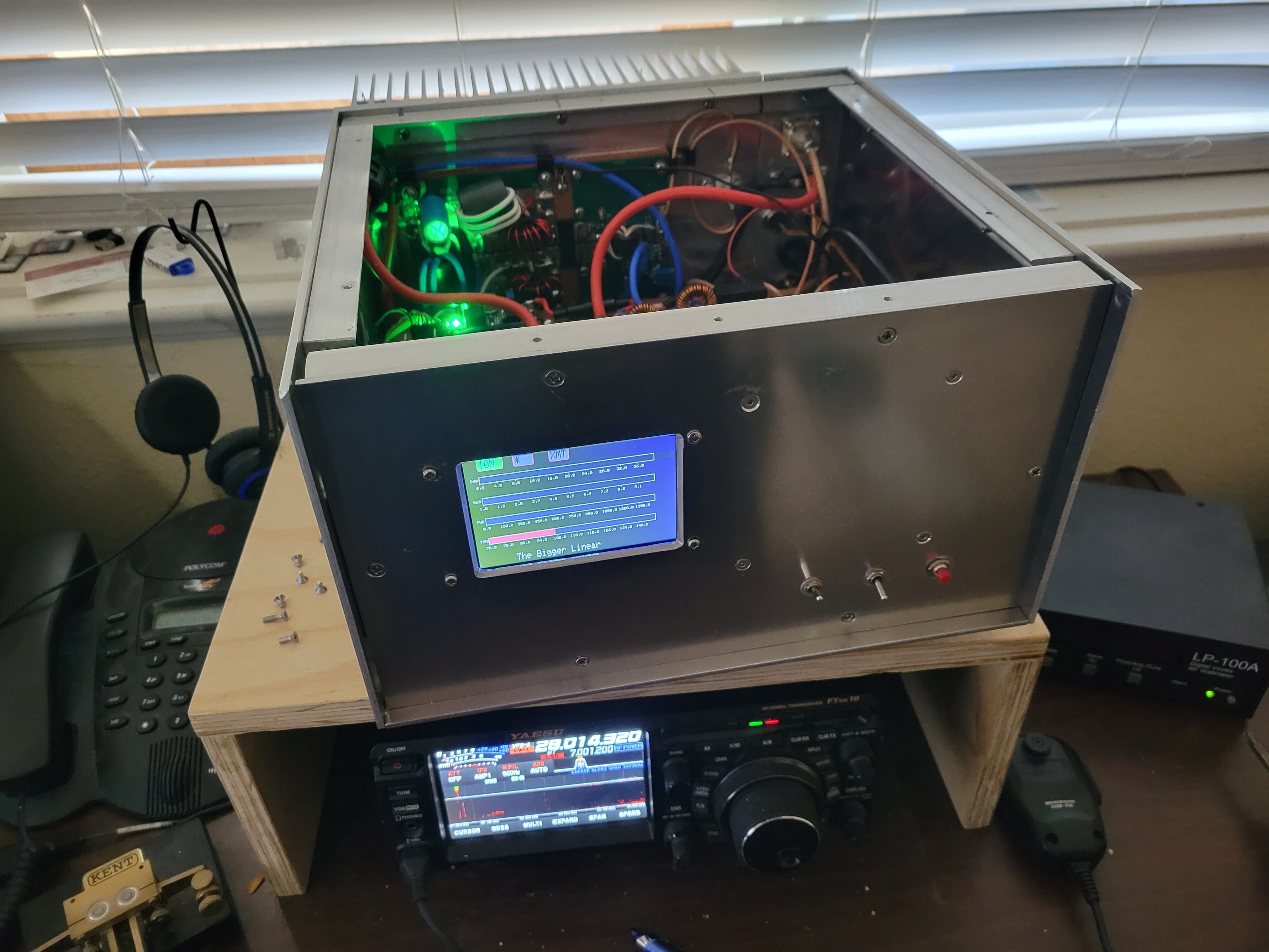
I’m looking at my latest electronic project - a high power Ham Radio linear amplifier with … can you guess?.. A pair of PWM-controlled Noctua fans at the back. And I wrote the code to control them.
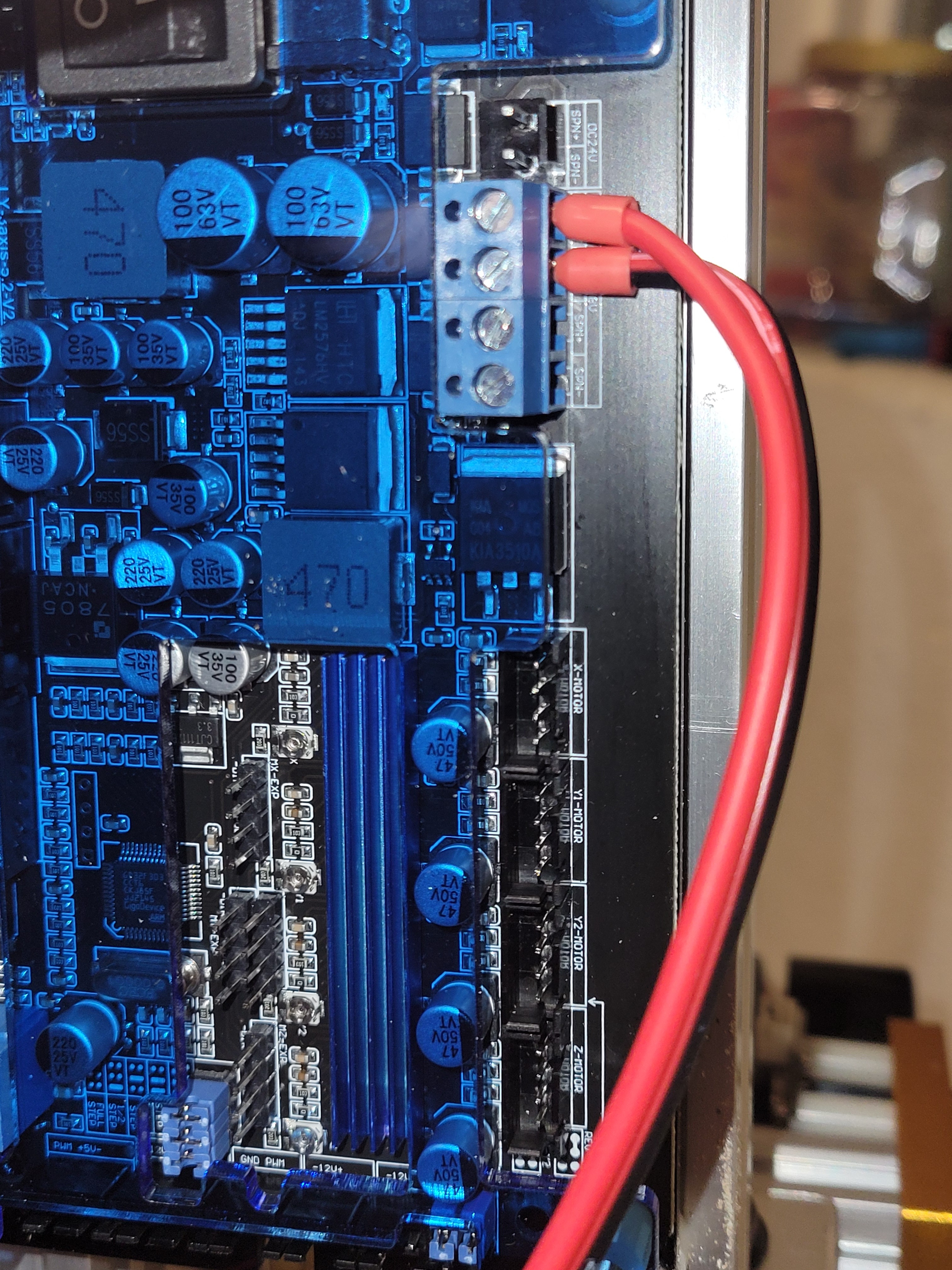
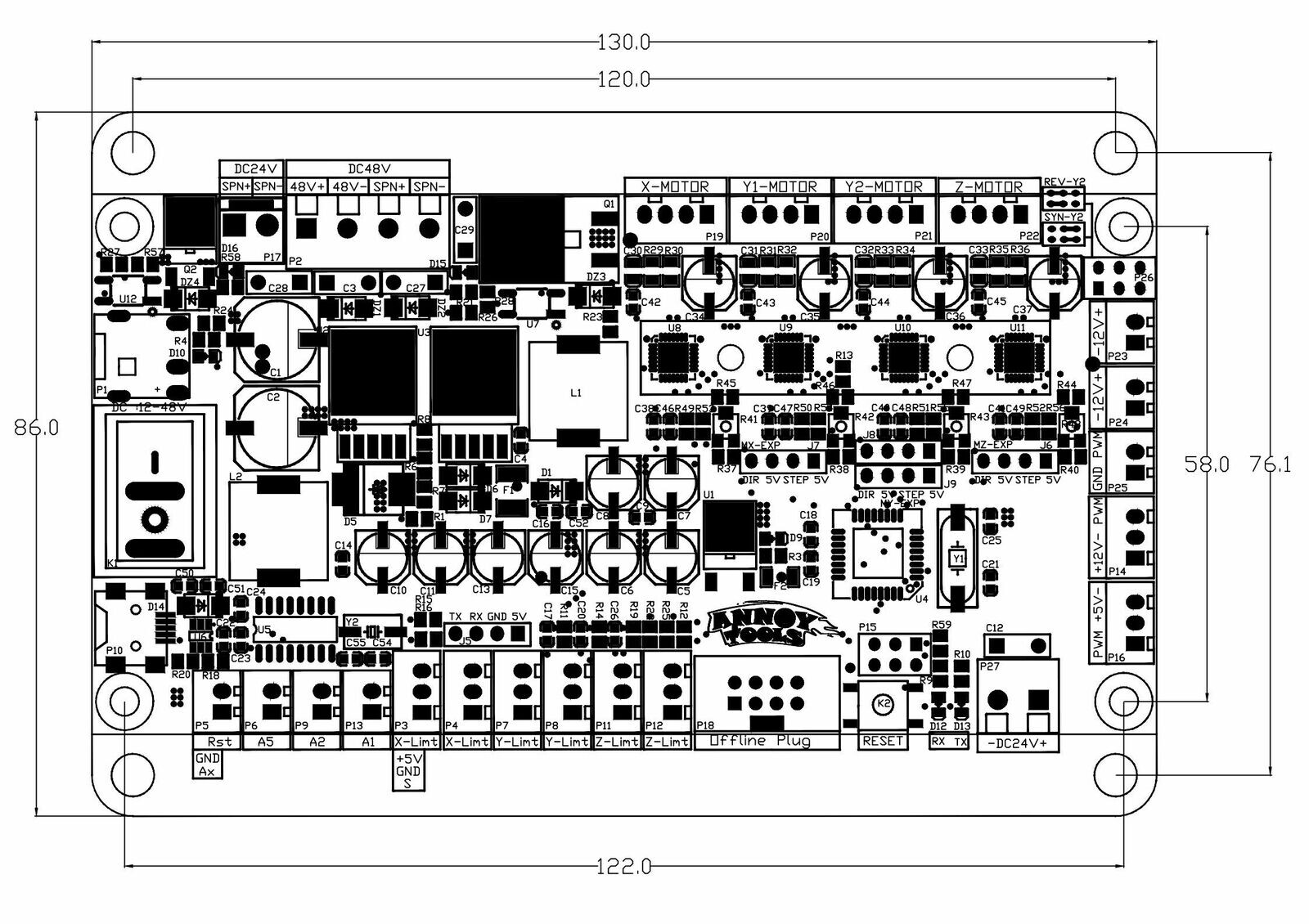
I suspect you’re right - the driver MOSFET shorted out. There is a large device right
next to the DC connectors for the spindle - “KIA3510A”. A quick search verifies
that it’s an N Channel MOSFET.
Exactly one listing on Ebay for such. I do have an SMD hot air rework station… wouldn’t
be THAT hard to unsolder it. I’d have to be careful not to melt the plastic connector shroud
right next to it. OK, 5 of those are on order.
Other interesting parts in that area include a pair of switch-mode regulator chips ( LM2576HV ) and their associated inductors ( the boxy things that say “470” on the top ).
Do any of these outboard controllers allow one to control the spindle with G-code? The ones I see just have a pot hanging at the end of some wires…
This failure happened while I was trying out the speed control - sending
S??? commands to vary the spindle speed, turning it on & off with M3 and M5 commands. I do fear that the circuit is simply poorly designed & inadequate for modifying the speed, and if I just leave it on Max speed, it’ll last forever. In which case, I might as well have a box with a pot at the end of a wire :).
Ah, yes, one of the great things here is that we welcome folks with all sorts of backgrounds, so we never know if the next person will be an EE or someone who has never touched a soldering iron.
Yeah, I have plenty of fans like that, I know exactly what you mean now.
Vdss 100V ought to be sufficient. Is there a flyback diode in there? (All this is obviously stuff you know)
It should be Repair, Reduce, Reuse, Recycle!
Mouser and digikey don’t show that part. I wonder if it’s pin-compatible with anything they do carry? TO-220 GDS — IRF3808 is 75V and might be easier to find legit parts and should be enough headroom for 48V?
To my knowledge, most of these control boards are not designed to drive spindles directly. Yours could be different. If I knew the model and manufacture of the controller board I might be able to provide more insight.
Usually, the output (PWM) is intended to control a high-power driver of some sort. I say this not knowing whats in the guts of the board you have.
Spindle motors typically are high current 48VDC and that is why you need some kind of power driver that accepts PWM and has a high voltage, high power switch to control the motor. Your correct that most controllers run on 12 or 24VDC.
If this is your case, you may have been trying to drive a high-current motor directly with the onboard driver and that was too much current shorting the output MOSFET.
As an oversimplified operation, these controllers convert G-code to a series of PWM signals intended to control a motor driver. These motor drivers often support both PWM and manual speed control. In the PWM mode, the input is usually a 5V PWM signal so the motor speed is controlled by the program
. In manual mode, the dangling pot controls the speed. These drivers are usually high-power H switches.
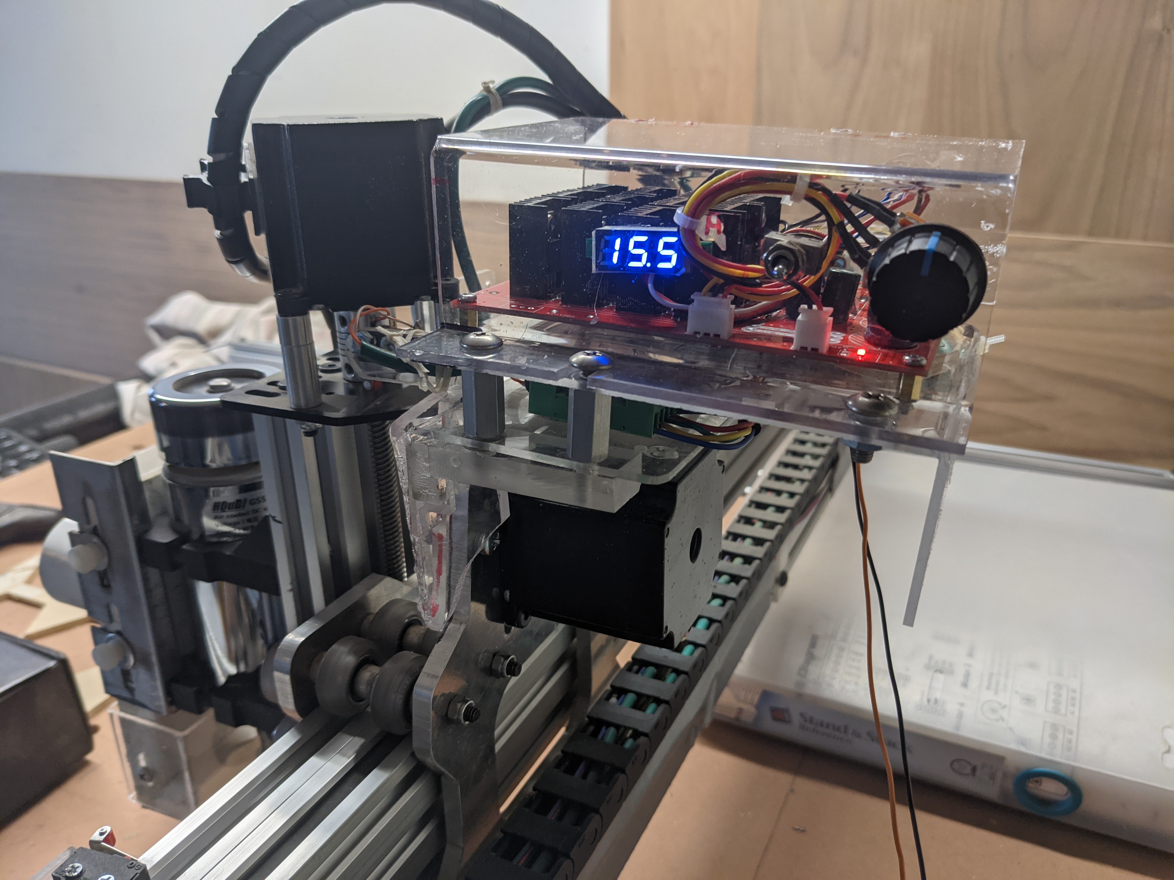
This is a photo of my 48V DC spindle motor driver as an example. I modified it from a china-made unit and it features PWM and manual control with a DVM to monitor motor voltage.
I think I have a viable theory. A motor looks like a big, low-Q inductor. What happens when you hit an inductor with a series of high-current pulses? Yeah, lots of inductive kick. Especially since it’s not a totem pole driver - just a series pass switch.
Wanna bet they didn’t indulge in a diode to kill that inductive kick?
If so, the fix would be to put at least a reverse biased rectifier diode
across the motor. Or a big zener - say a 60V one.
The motor probably draws 10A @ 48V. Is your controller powered with 48V?
The KIA3510A has a crazy high current rating (75A cont/215A pulsed) and an integrated diode. I have never trusted [for no good reason] integrated suppression diodes.
That’s a new one for me :). $34 controller and built-in spindle drive.
I wonder how the fidelity is on the PWM programmed value vs the actual duty cycle. Single-ended drivers do not usually reproduce PWM signals accurately.
This is a strange statement from the site: “The 48VDC interface cannot be connected to the switching power supply, and the voltage that can be passed through the DC seat of the control board cannot be greater than 5A” …
Hmmm, I have in my hands a baggie of IRF510’s. Wonder if one of those would work? It’s also a 100V power MOSFET.
Nope, won’t work. The maximum continuous drain current is only 5A. Whereas the KIA3510A is rated 75A.
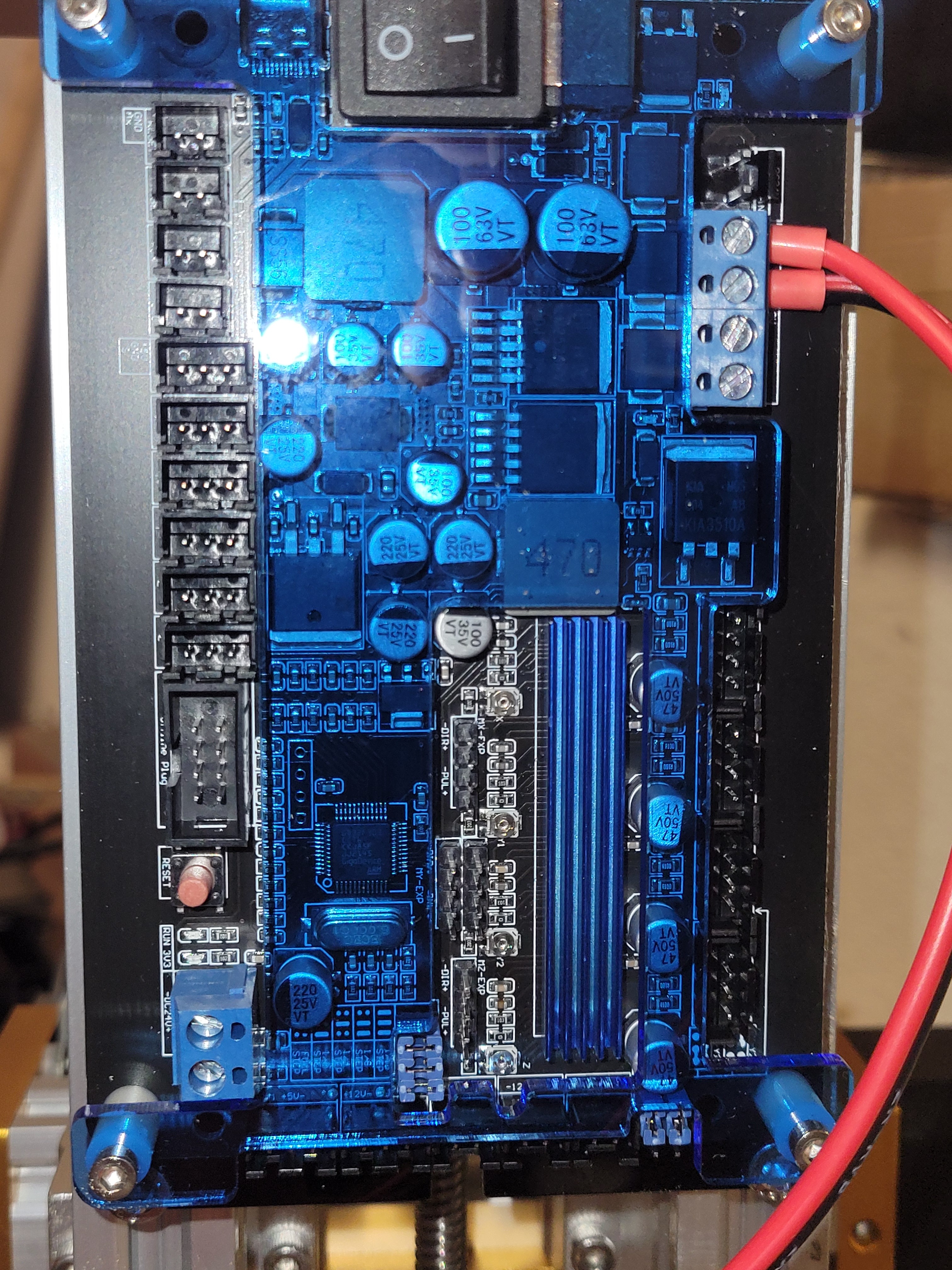
Close perusal of the board reveals that there is a separate 24V motor output. Don’t know its rating.
I unhooked the spindle motor and connected it to a lab supply. At 24V it does run. Nice & smooth. It pulls 600 mA. At
48V it runs faster ( duhhh) and pulls the same 600mA. Of course, that’s with no load. The current ramps up if I put some load on the machine by
putting my hand on the flywheel. It ramps up past the 1.5A that the
supply allows.
I could possibly connect the spindle to the 24V output and sort of limp along until parts arrive - I ordered a replacement board on Ebay from a USA vendor, and also 5 of the proper FETs from China.
Yeah, I also puzzled at that sentence about the switching power supplies. I’m guessing that they meant trying to power the board off a pulsed source. Otherwise, 48V is 48V - why should they care whether
the supply is switching or linear? Note the brand name “Annoy Tools” :).
Yes, 48V. The kit came with a switching power supply rated 48V @ 10.5A. With an annoying screaming fan. Unfortunately, in a size that Noctua does not offer
( 60mm x 60mm x 15mm ).
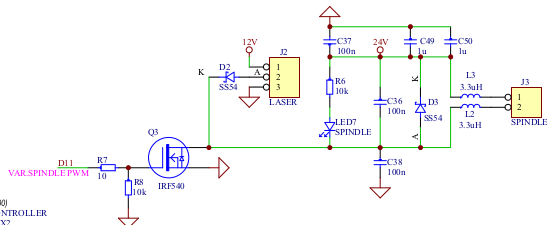
Probably much like my Woodpecker 3018. Here is the driving circuit for both the laser and the motor control.
I have a 500 watt spindle on one of mine, but it uses up to 100 volts and I vary it’s input via a pwm to voltage converter.
Even if the device can handle it, it’s assumed a good heat sink, which isn’t on these boards… Most of these boards are 1 oz copper and the width for 500mA is rather wide… I’m surprised at a 5 amp ability, that sounds more like the actual connector.
I’ve used the irl520 for many switching application, including to switch inductive loads. It’s reverse diode is good to 35 amps pulsed. I have not used snub diodes since these mosfets have had the reverse diode on them…
I assume this schematic is the drive section on the controller board?
What voltage are you using on the motor?
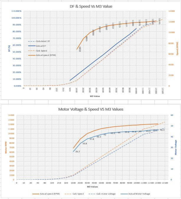
I would be interested in the fidelity of your programmed vs actual DF.
What I mean is if you program the PWM to be 50%DF what is the actual drives DF.
I have found that it can be quite far off due to switching delays etc in the driver.
I have tried multiple MOSFETS and gate driving schemes including push-pull.
I have never pinpointed why the MOSFET will not switch on/off in a reasonable time. I suspect some kind of DV/DT condition that keeps the gate on.
The reason this is a problem is if you are setting speed in a CAD program the actual spindle runs way too fast because the driver is not turning the motor on/off at the right DF associated with the M3 value. This ended up being a problem because when cutting wood the chip loads were wrong due to excessive speed.
I finally just built a graph and consider the error when I program the speed in Fusion. I don’t like this because it is hacking the speed in Fusion just to make the ugly driver work.
This is an example from a RIO-Rand (Chinese) driver. My newest one is better but still too much error.
The 24v input is shown in the middle top of the motor circuit. That mosfet has only a 55volt breakdown, so I wouldn’t put 48 volts on it, and no heat sink of any size…
So - I was closely perusing the Ebay listing for that identical board. I noticed that the output FET had different printing on it, than on mine. The device in the Ebay listing had an IR ( International Rectifier ) symbol.
It said
“F540NS”, “IR P023D”, and “K80D”.
Couldn’t find an actual part with any of those designators.
HOWEVER, I looked through the IR MOSFET catalog and found a likely
winner: the IRFS4410Z. This is rated 100V, 97A, 9milliohms “On” resistance. Same package: TO-263 with the pins pre-bent and the
drain pin cut short.
Ordered two of those from Mouser Electronics. Indulged in 2nd day Fedex.
Since transistors won’t be here till Monday at the earliest, I turned my attention to software. A CNC router isn’t much fun without stuff to engrave. I am presently climbing the brick wall learning curve of Freecad. I have used it in the past to create designs for 3D printing.