So I’m attempting to make a silicone mould of a rubber valve which I’ve already modeled in FreeCAD.
My problem is I think I’m approaching it incorrectly because I then created a top mould case with tapered pins and I then modeled a bottom mould case with cylindrical alignment receiver pockets so 3 separate parts in 3 files. I had thought that an assembly workbench would be where I’d combine these and take the difference of the valve from the 2 mould casing halves but Assembly 3 looks like it’s literally just for putting stuff together. Other tutorials on assembling appear to be similar.
I’ve been looking for how to take one case mould half and add the valve part and take the difference and then repeat the same for the other mould half but not having luck yet.
Any pointers while I continue to figure this out would be helpful. Thx
update 1:
I thought I had the answer by loading all 3 parts into FreeCAD, selecting the Valve body then by selecting the mould case view(bottom tabs) then the Link toolbar icon I ended up with the Valve body linked within the mould case half and thought Boolean cut would not work. NOT. The boolean union option is available in the Part workbench but in Part Design I can’t add the valve part to even start select a boolean operation.
update 2:
I did it by loading all three parts into FreeCAD, selecting the model body of the Valve part and then Copy(Ctl-c), move to select the body of the mouldTop and Paste(Ctl-v), repeat Ctl-v because I want to make 2 valves in one mould. I then selected the newly added Body001, selected Transform and shifted it left 12mm. Selected the Body002, transformed shifting it right 12mm. Now select the mouldTop body, then Boolean operation where I can then select each of the 2 valves, the Cut operation and voila.
These cuts have no connection with the original valve so any changes to the original means repeating the whole copy/paste/xform/Cut operations…
I’m thinking I should have made all of these parts in one file, did all the operations with clones or some form of ‘linked’ operation and then export parts by selection rather than have each part a unique file/design.
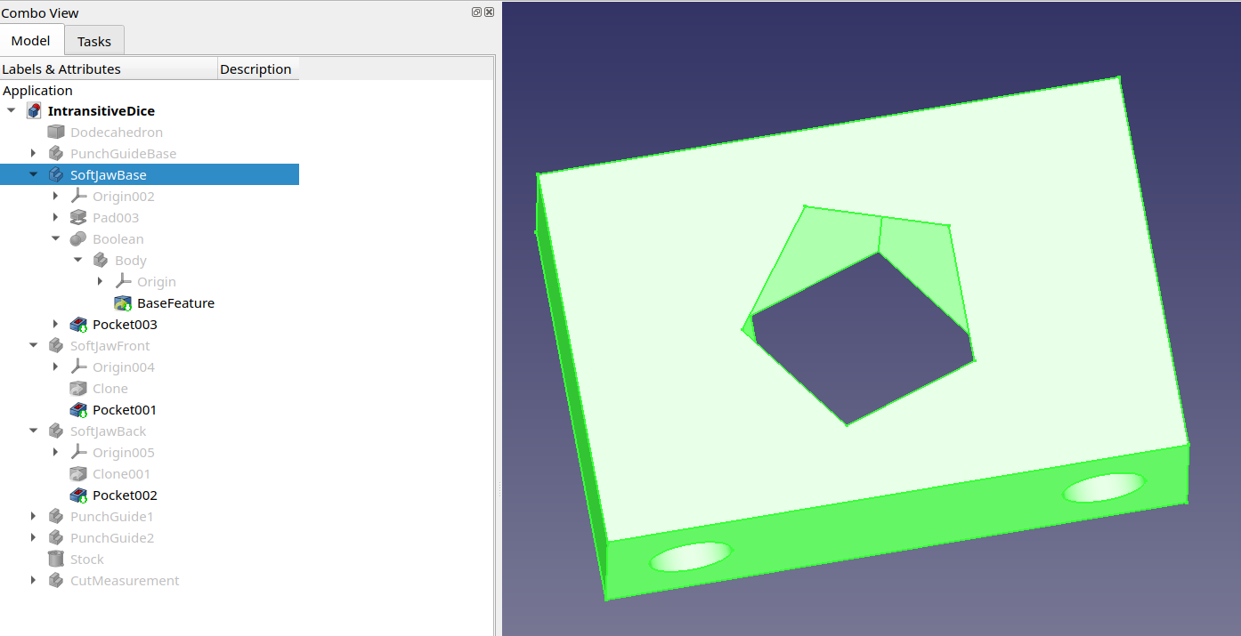
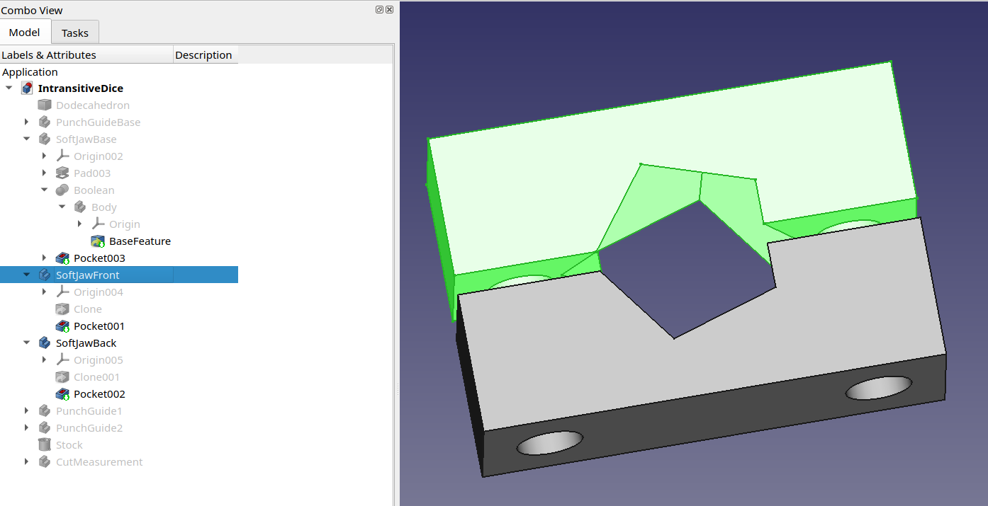
There are other objects in that file; it’s what I used for all my intransitive dodecahedral dice calculations. But if you look at those three objects in the tree, it might help you. The difference between custom soft jaws with alignment pins (though in the end I didn’t use the alignment pins) and a mold is not super relevant here.
I will experiment further since even though I now have the 2 STL files making up the 2 halfs of the mould I want to learn better procedure getting there. I hadn’t thought about doing a full mold block with the negative part space inside it and then cloning the blocks, removing opposite halves and then adding the guides and pour holes. I will give that a shot.
What I thought I’d be able to do was to ‘import’ my Valve design/file in such a way that changes to the original would follow when the Recalculate was activated. Linking does that but it seems boolean operations aren’t active with linked elements. I think cloning might work but will experiment further.
I will take my original single-Valve design, clone the part and translate the original X-12 and the clone X12 which should put them in the mould were intended. This way there’s no manipulations or xlations of the Valve(s) needed but for doing Boolean operation on the mould body.
Posting the question of why linked objects can’t do Boolean ops to the FreeCAD forum is next.
Looks like clones of parts also can’t be used in Boolean operations. ugh.
I took my original Valve part, shifted the sketch -12mm along X, cloned(Draft workbench) the 3D part and moved the clone 24mm along X and saved the file as pumpValves. I verified changes to the original spreadsheet migrated to both original and the clone parts.
Then I brought in a backup of the mouldBottom part, copied the pumpValves part and pasted it into the mouldBottom part so they were all in the same design file. Well, the paste only brought over the original pumpValve part so I cloned it within the mouldBottom design and then tried to do a Boolean Cut operation between the mouldBottom design body and the 2 pumpValve parts and only the original pumpValve is able to be added to the operation.
So I can do Booleans on a part using a single, original, part but if I’m making something which uses duplicates of the same original part then it doesn’t work. mouldCasingBottom.FCStd (30.0 KB)
So far my only way around this and still have the parametric capabilities desired is to copy the pumpValve twice into the mouldBottom but on the 2nd copy I don’t copy the Spreadsheet so this way both copies use the same parametric sheet. It’s not as good as having one Original designed pumpValve and create links into the other mould half objects but it works. I could also do as Michael did by putting the desired part, pumpValve(s), into a block and make the cavity(pocket) then copy that block and make the top and bottom halves from it.
I took a look at it and it did sound like it was something like what I wanted but it did not work out that way.
When I created the subShapeBinder link the second I hit the transform button to shift its position on the new body I was shifted to the original model.
When I use the standard Part Design Link tool I can move the linked objects around on the larger part’s body but can’t do Boolean operations with it.
Having come from OpenSCAD I’m kinda a nut about parameters so pretty much everything can be tweaked. What seems odd is I would think this is a standard CAD operation. ie you make a custom fastener shape like maybe a screw-like bolt and then you go all around a larger part doing Boolean cuts of your ‘screw-like bolt’. But to do that, it seems like we have to copy and paste the original in every place we want to do the Boolean cut and unless you setup a global parameter spreadsheet, these copied object will have broken parameters or you end up with a dozen different parameter spreadsheets in your design and have to go into each one if you realized you need 3mm more depth.
I’ve only got 2 different halves of the mold to deal with and I figured out I can copy one parameter sheet with the pumpValve part and the 2nd copy I exclude the spreadsheet so only that sheet in that half of the mould needs manipulating to adjust the pumpValve. So I just need to do it to 2 different design files.
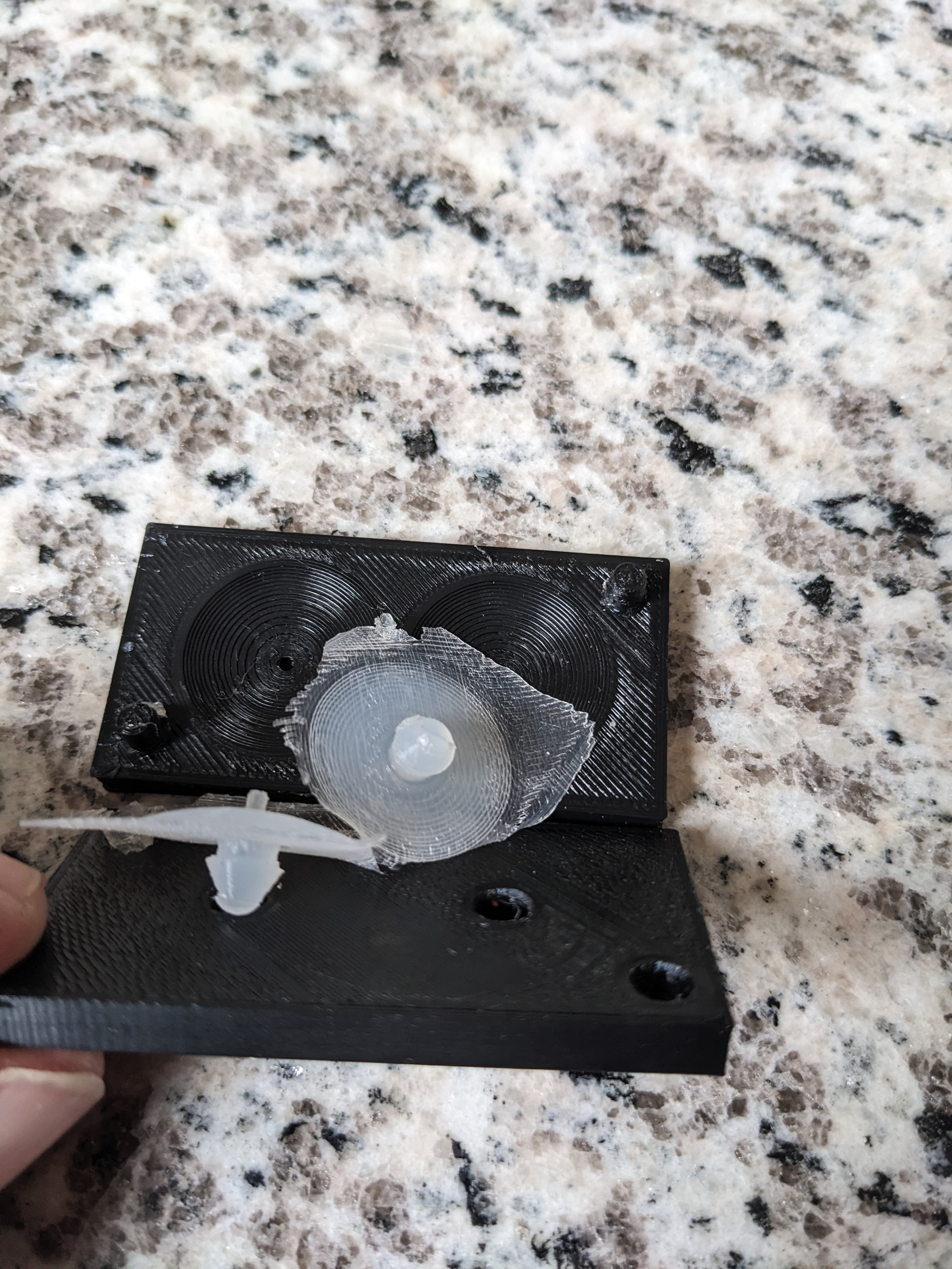
Having 3D printed a sample, the ridges of the curved pumpValve flap will make the “positive” product too thin so I have to adjust a parameter and try again. Just one parameter in 2 different files so not a big deal. Just not elegant.
Oh, I always have to read docs for that and PartDesign ShapeBinder - FreeCAD Documentation to remember which one to use. I see ShapeBinder is the one that lets you choose whether it traces the underlying object position.
It’s probably handy when the object being bound is a larger and more complex part so it’s just going to be one part.
I guess when people bring in screws from McMaster Carr or some other library they only position them and don’t use them for anything like a Boolean Cut to make the hole.
I would not be surprised to be called an oddball for what I’m trying to do.
I don’t think this is odd. When I have a bit more time I’ll be happy to look at your file, and try to come up with a different approach that works better. Just squeezed for time right now so trying to get by with pointers…
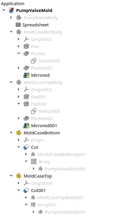
Since this is a pretty simple design/task I moved all parameters to one spreadsheet and I created 1 document/file containing the 3 main parts.
pumpValve
mouldBottom
mouldTop
I need to make 2 pumpValves so I shifted the original pumpValve part -12mm on X axis, copied it without the spreadsheet then pasted it as a new part and shifted it 24mm along X axis.
When I did the first Boolean operation on the mouldBottom part using the 2 pumpValve parts, they are removed from the top level part list so can’t be used for the 2nd mould half( mouldTop ). I can make 4 copies of the pumpValve but wonder if there’s not a better way.
Final design with help from Michael and others. Part Workbench is definately helpful. This update also included a 1mm rim/thickness to the edge of the valve flap element and I added .8mmm to the diameter of both the valve stem diameter and the locking step diameter. Working great and so far no signs of the vinegar acid deteriorating the valve. And if it does, I can easily make 2 more.
OMG there must be lots of FreeCAD users on the FreeCAD forum who do, or have done, injection mold making. I really just should have asked how to efficiently do a bunch of boolean operations of a common Part with a few other Parts in the same document/design.
What I got was lots of info, document links and forum discussions on how to make designs for injection molding. My head is spinning from spending the last 4 hours on this and it really looks like it’s just easiest to make copies of the one pumpvalve and do booleans and let each part consume the copies.
So finally playing with this while watching a print…
There was talk years ago about making Links usable within Part Design Bodies but it looks like that doesn’t work. And right now, you can’t have any step in the design tree for a Part Design Body that has a discontiguous shape.
I think the best option is to actually use the Part workbench for the final steps. Use Part Design to design parts. But then use Part and Draft to put them together.
I used “Mold” instead of “Mould” so I could keep my two tabs in FreeCAD separate. Please feel free to rename them if you prefer that spelling.
General workflow: Create a link of the valve, then use Draft Array to make two of them 24mm apart. Create a Part to hold one of the final mold halves. Link one of the mold half base parts. Select the link to the base Part Design Body, then select the array, then boolean cut, then drag the Cut object into the Part. Create another Part to hold the other final mold half. Create a ink to its associated base Part Design Body. Create a link to the Array that is now inside the first Cut. Select first the link to the second base mold half, then to the new link to the Array, then Boolean Cut, then drag the Cut object into the second part.
I hope I remembered all the steps.
Edit: Using my flow, the vent holes could be added to the base Part Design Body and they would flow into the Part with the Boolean.
I noticed that you used 1mm dimensioned circles in your sketches in the file you just uploaded, but then the holes don’t use that 1mm radius dimension. Was that intentional?
Here’s a new version of that file using 1mm radius pocket instead of a 6mm hole, and using a single hole and a mirror instead of two dimensioned holes.
I’ll give your workflow a try and see how it feels. It sounds like linking works with your workflow. I just couldn’t get it to work in the Part Design wb.
I did that when I noticed that the Hole operation defaulted to it’s own dimensions. Otherwise I might have parameritized them too. Good point that those vent holes could be included in the valve sketch.
Yeah. I find that I live in Part Design most of the time, and find its opinionated workflow convenient for almost everything I do, but the Part / Draft / Sketch combo is more general and powerful.
Holes can be parameterized through their data, but they use circular features only for the center point, and completely ignore their dimensions. They are for modeling complete holes; things like threading, countersink, counterbore, etc.
Holes are good for interfaces with screws, bolts, alignment pins, etc. Pockets are what you want for “just do what I put in my sketch”
I over-compensated and used Pockets everywhere for a long time, and finally started using Holes for the features they were designed for more recently.
This video might help getting started with the Part workflow if you are new to it.
Looking at your file it appears that you got over the issue with multiple pumpvalve objects by creating arrays of them. It seemed tedious but it was probably because I was reading a doc on how it works and following. And I see how you positioned the 2 pumpValves in the array so there wasn’t any translations needed when dropped into the case bodies.
Also liked how you made the case with it’s guide pins/holes and vent holes as their own body’s and then created another body for doing the cutting of the pumpValves.
The workflow I finally fell into ended up with not too much “copying” of the pumpValve sketch. But I realized 3D printed would be better if the pumpValve were positioned with the large diameter part in the case/mold with the pins so the barbed part of the pumpValve could be printed without overhangs. That required a sketchpad mirror. But from there I just made a copy and moved it into the target case/Body.
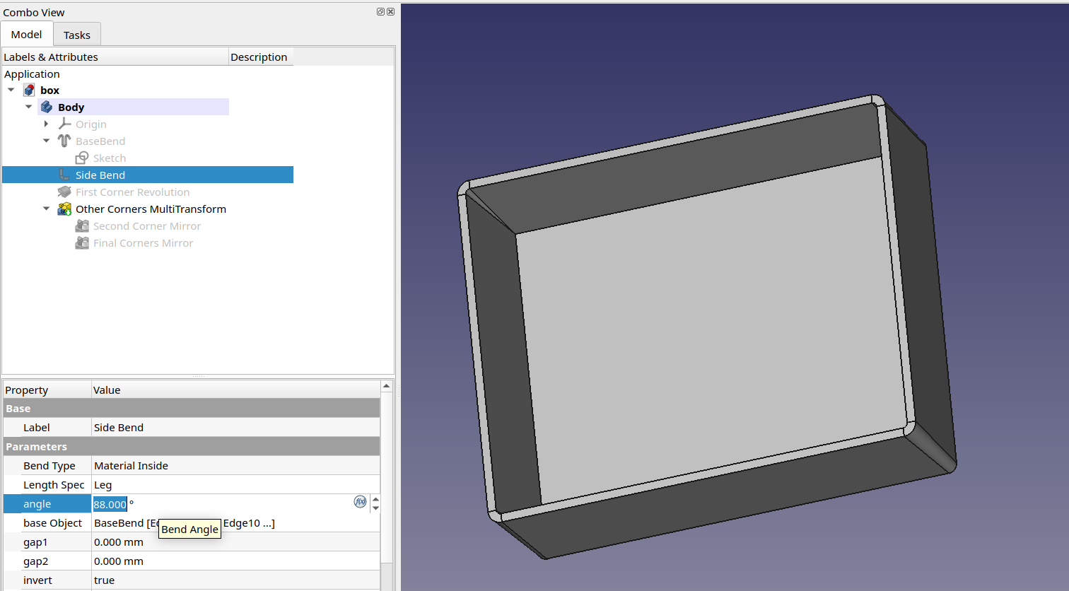
The MultiTransform / Mirror operation created a new cavity.
So I definitely learned a few things and after I do your workflow a couple of times I think the array and linking mechanisms of Part wb will be understood. Thanks for plugging away at it.
Yup. And Draft has a bunch of other really powerful tools like that.
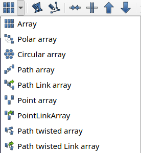
Those path arrays can follow an arbitrary wire, even a b-spline. I haven’t checked whether you can compose wires from sketches in different planes to do 3D arrays though.
Using an array of other pieces something you just can’t do in Part Design because every part has to be a single body. And AFAICT Part Design booleans can only be with bodies. I tried with the Draft Array and it didn’t work. The array-like tools in Part Design (including mirrors) work only on features not bodies.
The Part / Draft / Sketch workflow is a little tedious because of having to change workbenches all the time. Fortunately, as this demonstrated, you can use Part Design parts inside the Part / Draft / Sketch workflow, so you can use easy mode most of the time — at least, for those of us who find Part Design to be easy mode.
So I expect to continue using Part Design for almost everything I do, but recently I’ve gotten more comfortable with the idea that 5% of the time I’ll be moving to the Part workflow.
This is ironic, since I came to FreeCAD from OpenSCAD which is, of course, much more like the Part workflow than the Part Design workflow.
I also tend to do most of the parametric modeling of shapes in Part Design and then go into Part and Draft for booleans, arrays, etc. I have started using Curves a bit more often but I’m still learning its quirks.
I’m happy to see discussion of mold making as I’m in the early stages of learning to cast metal. So, different forms than injection molds but I think similar approaches in CAD.