Filament (PLA) printer. Discrepancy between precision of ID and OD in same model

I was talking yesterday to my godson, in training as a luthier, about your project… Got me thinking.

Would your design work if you used 12mm precision ground silver steel / tool steel rod through to whatever bearings/bushings you have intended, and then threaded the ends with a die to take a nut?

I’m not suggesting you make the change now, but if you find out that runout from the M12 allthread is too high in practice, then if your design allows you to make that substitution to improve runout, it will be overall cheaper than starting over. :relaxed:

Separately, a source of grippy rollers is dead laminating machines. The laminating machines heat the rollers up and run them top and bottom, but you could repurpose them. (I have two such rollers sitting around waiting to be reused in some project from my first laminator failing…) If you have thrift shops handy, you might find a $5 source of rollers at one. :smiley:

1 Like

I cringe every time I see someone show or mention using AllThread for axles without bearings. Spinning metal on top of threads is bad enough but plastic on threads is great if you’re wanting a larger and larger hole in your plastic.

The OP seemed adverse to purchasing taps and dies since it’s been the obvious fix for his inner thread problem and even the cheapest of taps would work on plastic.

@dougl to be clear, @NotTheMama initially expressed concern that taps would reduce precision.

I haven’t seen anywhere here a reference to not using bearings. I think you are maybe making some unwarranted assumptions.

ah, I guess I missed that. Was pretty lucky he found the exact tap he needed and it worked.

Yes, since I didn’t recall seeing bearings mentioned it was calculated that there were none. AllThread is great for structure and such but all too often I see maker projects using it for an axle which even greased really isn’t really a good idea unless just a prototype setup.

It seems that my project has sparked your interest (I appreciate it) - I hope that these pictures make things clearer - Note the 12mm smooth steel axle going through flanged bearings (hidden from view, inside the laminated timber blocks) and the Green PLA 3D printed hubs. There are four of these, spread evenly inside the cylinder.


I tried a few different designs for the hub locks, and settled on grub screws, but I am not entirely pleased with that. For the infeed and outfeed rollers I would like to try threaded hubs with lock nuts. Mainly because I have 2m of M12 all thread in my workshop that I would like to use for something. I intend to make some spacers and have the M12 axle run on bearings as well.

Thank you for the interest - Perhaps you can PM me if you want to discuss the sander design further.

Regards

Jorge

@dougl You need not cringe on my account.

The sanding drum has a 12 mm steel rod axle and runs on flanged bearings

I am using M12 all thread for the in/outfeed rollers because that’s what I have lying around in my workshop… It too will run on bearings after fitting spacers. There are other reasons why I want to use the M12 all thread and threaded hubs.

Using a drill press to increase the diameter of the hole in the hubs those holes acentric and introduced wobble. I don’t expect that this will be a problem when using the tap to increase the tolerance of the M12 thread.

The subject of the OP is that my parts are precise in every dimension except for holes and threads. I would still be interested in having my holes and threads print exactly as I draw them on FreeCAD without resulting to fudging and trial and error, but it seems that achieving that is a lot more work than it’s worth.

Thanks for sharing more about the sander! If you ever feel like sharing more about that design (perhaps in Crafts?) that would be interesting. I don’t go do DMs; I invest my time running this site to make ideas available to others. :smiling_face:

I am guessing that the infeed and outfeed rollers will be spring loaded? In which case slight runout won’t have any impact in any case…

Yes, perhaps I will - The only reason I suggested a DM is that the last few posts were off topic. There are 100’s of videos on how to make a sander, but none that I’ve seen use 3D printed parts and none feature in/outfeed rollers

Correct! Pressing down on bearings sliding on a vertical track.

Regards

Jorge

1 Like

Cool! No pressure to share, only welcome opportunity if you’d enjoy sharing. :relaxed:

I know that you worked around this in the model and solved it, but since you were originally asking why it was necessary to do that, I wanted to follow up…

I just learned that Cura has a Hole Horizontal Expansion parameter. I can’t find an exact analog in prusa-slicer (I see “XY Size Compensation” mentioned as the analog but it obviously isn’t).

SuperSlicer also mentions such functionality relative to Prusa-Slicer on which it is built:

Options to change holes dimensions and/or geometry, to print them at the right size.

I haven’t installed SuperSlicer (I note that its AppImage says that is for Ubuntu; I haven’t tested whether it works on Fedora) to investigate further, but this is interesting to me so I might do that.

2 Likes

An update on the original post.

Recap: I’ve had a Tevo Tarantula for a few years and use FreeCAD and Repertier Host/Slicer to create 3D printed parts - But the internal diameter of the holes in the parts is always undersize when every other dimension in the model is precisely as drawn on FreeCAD. I’ve tried a lot of things to solve this recalibrated the machine and the filament but I’ve had to settle with drilling the holes and tapping threads once printed.

I recently bought a DOBOT MOOZ-3 delta printer for very little money (on special at a local store) and it proved difficult to set up on Repertier/Slicer but came with instructions for how to set up in Ultimaker Cura. I tried to print some threads and holes on it and all parts of the models turned out to be precise! My new theory, to be tested in the next few weeks is that 1) Cura somehow “slices” holes differently to Slic3r and Prusa or 2) there are differences in Marlin between the two printers or 3) The filament PLA vs PLA+ is behaving differently or 4) a combination of the three.

I will try printing hole calibrators on the Tarantula sliced with Cura and see what happens.

Cheers

PS: @mcdanlj I finished the thickness sander and it works a treat! I now have enough 2 mm wood veneer (sanded from 3-4 mm) to make several ukuleles and lutes. The sander relies on several 3D printed parts with low tolerances on diameter and other dimensions.

2 Likes

Awesome! Thanks for the update here, including the success of the underlying project!

I just fired up Cura to check, and it looks like the default value for hole horizontal expansion is zero, but the fact that it has that parameter makes me wonder whether it actually still does holes differently from slic3r or prusa-slicer, even when it’s set to zero. So the hole calibrator comparison between slicers sounds really interesting.

1 Like

Registration between parts is a complex business and entire books are written about it. In general, it’s best to think of each part (including fasteners) as springy sponges. As Michael commented, shapes like nested tapers are great for registration. They allow the parts to stretch around each other in a known way and in a specific axis or movement.

The only other general tip that I think is relevant is to prioritize one axis for a precision fit and allow for the rest to be a bit sloppy. It’s terribly tricky to hit precision interfaces for two or more axis of movement.

2 Likes

@mcdanlj

Update on calibration experiment CURA vs Slic3r.

Summary of results:

In order to tests the hypothesis that the diameter of holes in 3D printed parts are more accurate when the GCODE is generated using Cura, I 3D printed two calibrators. The only difference between them was the slicing software used to produce the GCODE (Cura, vs Slic3r).

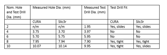
The X-Y accuracy of a rectangular printed part was slightly better when sliced with Cura, but the accuracy of the diameters of 2-10 mm holes was not appreciably different between the two slicers. The 2 and 10 mm holes were more accurately printed the 4, 6 and 8 mm holes were appreciably undersized . The latter result suggests that registration tolerances require a finer resolution than what my 3D printer fitted with a 0.4mm nozzle is producing with the current settings.

Detailed Description of Experiment and Results:

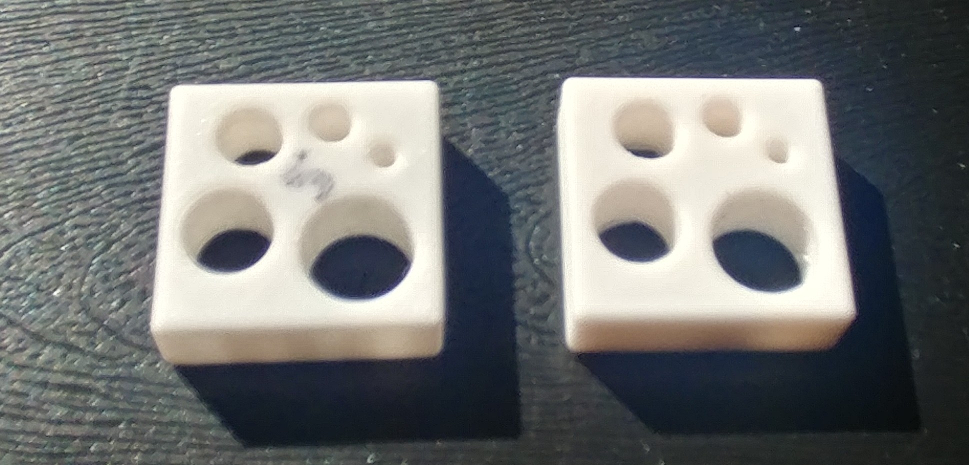
As an experiment I used FreeCAD to draw a 25 x 25 x 8 mm rectangular prism with 5 holes : 2, 4, 6, 8, and 10 mm (pictured), and exported the design to STL using FreeCAD’s inbuilt export facility.

I then used both Slic3r and CURA separately to produce separate GCODE files to print on a Tevo Tarantula Cartesian printer. The print and filament settings were the same in CURA as they were in Slic3r (see below). The Filament was used was the same in both prints (Tevor PLA+). The two parts were printed on the same day one after the other. In other words everything was the same between the two prints except the slicer used to produce the GCODE.

The dimensions on the printed parts was measured with Vernier callipers and the chuck end of a drill was used to check for fit in the holes in the calibrator thing.

Results

Part Nominal Dimensions 25 x 25 x 8 Result with Cura 24.95 x 25.05 x 8.18 Result with Slic3r 24.84 x 24.87 x 8.11 (Cura appears to be slightly better in XY accuracy)

The other results are summarised below:

Untitled

Below I’ve copied what I feel are the most relevant printer and print settings.


bed_temperature = 75
bottom_infill_pattern = rectilinear
bottom_solid_layers = 4
cooling = 1
disable_fan_first_layers = 2
dont_support_bridges = 1
duplicate_distance = 6
end_filament_gcode = “; Filament-specific end gcode \n;END gcode for filament\n”
end_gcode = M104 S0 ; turn off temperature\nG28 X0 ; home X axis\nM84 ; disable motors\n
external_perimeter_extrusion_width = 0.4
external_perimeter_speed = 50%
external_perimeters_first = 0
extra_perimeters = 1
extruder_clearance_height = 20
extruder_clearance_radius = 20
extruder_offset = 0x0
extrusion_axis = E
extrusion_multiplier = 1
extrusion_width = 0.4
fan_always_on = 1
fan_below_layer_time = 60
fan_percentage = 0
fill_angle = 45
fill_density = 10%
fill_gaps = 1
fill_pattern = rectilinear
first_layer_acceleration = 0
first_layer_bed_temperature = 75
first_layer_extrusion_width = 0.4
first_layer_height = 150%
first_layer_speed = 30
first_layer_temperature = 225
gap_fill_speed = 20
gcode_flavor = reprap
has_heatbed = 1
host_type = octoprint
infill_acceleration = 0
infill_every_layers = 1
infill_overlap = 55%
infill_speed = 60
layer_height = 0.1
max_fan_speed = 100
max_layer_height = 0.35
max_print_speed = 60
max_volumetric_speed = 0
min_fan_speed = 35
min_layer_height = 0.1
min_print_speed = 10
nozzle_diameter = 0.4
overhangs = 1
perimeter_acceleration = 0
perimeter_extruder = 1
perimeter_extrusion_width = 0.4
perimeter_speed = 30
perimeters = 1
raft_layers = 0
regions_overlap = 0
resolution = 0
retract_before_travel = 2
retract_layer_change = 1
retract_length = 5
retract_length_toolchange = 10
retract_lift = 0
retract_lift_above = 0
retract_lift_below = 0
retract_restart_extra = 0
retract_restart_extra_toolchange = 0
retract_speed = 40
seam_position = aligned
skirts = 0
slowdown_below_layer_time = 5
small_perimeter_speed = 15
solid_infill_below_area = 70
solid_infill_every_layers = 0
solid_infill_extruder = 1
solid_infill_extrusion_width = 0.4
solid_infill_speed = 30
spiral_vase = 0
support_material = 0
temperature = 210
thin_walls = 1
threads = 4
top_infill_extrusion_width = 0.4
top_infill_pattern = rectilinear
top_solid_infill_speed = 30
top_solid_layers = 4
travel_speed = 40

1 Like

:heart: experiments! :heart:

I’m guessing you already know this since you used drills as ersatz gauge pins, but for anyone following this who doesn’t… Measuring holes with calipers leads to an undersized measurement because you are measuring the distance between two chords (flats on calipers) and the amount undersized is greater for smaller holes. That is, the error is not only lower as a percentage of true hole size but also absolutely smaller as the hole gets larger. Machinists have all sorts of specialized tools for accurately measuring holes, most of them very expensive. :grin:

One thought about your experimental setup between printers:

This feels possible, FWIW. The mystery toughening agents denoted by the “+” in PLA+ may also change filament viscosity, which could definitely affect internal diameter fidelity.

Blockquote
I’m guessing you already know this since you used drills as ersatz gauge pins, but for anyone following this who doesn’t… Measuring holes with calipers leads to an undersized measurement because you are measuring the distance between two chords (flats on calipers) and the amount undersized is greater for smaller holes.
Blockquote

Yes and you will also have noted that I did not even try to measure the 2 mm hole - I guess I could have done it photographically with a ruler placed alongside the holes for scale. I felt this was overkill…

I was most surprised that the 2mm and the 10mm holes were in fact accurate (well oversized) enough for the respective drills to fit through but the 4 6 and 8 mm holes were slightly undersized. This occurred with both sets of GCODE. This not only debunked my original hypothesis but now leads me to believe that printing with a 0.4 mm nozzle does not produce sufficient resolution to produce parts with the accuracy and precision that I sometimes need.

The PLA+ is definitely better - but the manufacturer recommends a bed temperature of 75 ºC and the extrusion temperature of 225 ºC, these are very high compared to normal PLA, but I like the results, and the interlayer adhesion is superior I think.

Incidentally I got the notion that CURA sliced parts were more precise when I measured the inside diameter of a 10mm hole that I printed recently. I now know that a 10 mm hole will always be “spot on” using my set up no matter which slicer I use. It would be nice to understand why 10 and 2 mm and not any other.

If I ever find out why I will tell you…

I can think of a few ideas.

The filament will pull viscously into the center before it cools below the glass transition temperature. As the radius gets larger, this will have less impact.

As the radius gets smaller, it will slow down more, and will not run at the full small_perimeter_speed, which will also reduce that impact.

If you want to test this, you could try the blocks with a small_perimeter_speed of 5mm/s and see if it’s closer for the intermediate sizes?

I’m also curious whether using Arc Welder would change things.

This conversation reminds me that I want to design an optical comparator for home shops. They really are great tools for situations like this.

2 Likes

That’s not a good choice if you’re looking for accuracy. 3DP nozzles work by controlling the pressure inside the extruder which keeps the extrusion width accurate. Rule of thumb is the minimum setting of 110% of the nozzle diameter. When less than 110% there’s no control in front of the nozzle(in the direction of motion) and no control on the sides so all you have is the flattening effect on the back side of the nozzle end.

You also want to print external perimeters first. They will be the ones defining the hole and by printing them first, there are no adjacent perimeters to deal with which can cause sideways pressure on the extrusion. And by doing 3 or more perimeters this also locks the plastic in position so that any fat infill can’t push the perimeters inward and mess with tolerances.

The sides of the extrusions are rounded and the slicer sets the position of the next adjacent extrusion such that the interfacing side overlaps enough to push the rounded bulge into the under and over cut of the previous rounded extrusion profile.

@dougl - Yes you are right - I used the default Cura parameters (I’ve only just started using Cura) and only really thought about it after the fact. I also printed a separate calibrator with single perimeter walls to check single wall thickness accuracy (its good) and left the setting as is for this experiment. I think that the comparison between Cura and Slic3r should still hold though (basically there was no appreciable difference)… but with so many variables who knows! :slight smile:

I might try re-slicing/reprinting with 3 perimeters, 0.44 line thickness, outer perimeters first - But I tried all of this before and it did not make appreciable difference. I figure that I am just reaching the limits of resolution for my set up, and its actually pretty good when you look at the numbers.

It strikes me that the calibrators that I designed will make nice key rings or earings or something :wink: