There is a fairly tight tolerance on both the Outer Diameter (OD, 94mm) so that the part fits inside the cylinder, and Inside Diameter (ID, 12mm), so that the part does not wobble on the axle.
I draw the parts on FreeCAD, and export the design to STL which I then slice in Repertier/Slic3r.
The problem is that - invariably - on a properly calibrated printer, the OD is correct, but the ID of the same part is too small. My solution has been to draw the ID as 12.2 mm but feel that this is an inelegant solution and would like to be able to trust that my CAD designs will print as drawn.
More recently I’ve drawn an M12 nut using FreeCAD standard tools. The thread is well printed but has to be forced onto a standard M12 bolt.
I think that this may be happening due to differential shrinkage between the outer surfaces and inner surfaces in the PLA, but I can’t exclude a quirk in the way that FreeCAD produces STL or the way that Slic3r slices them.
Has anyone had a similar experience? Any solutions that are better than mine or trial and error?
I’ve never seen it otherwise. It has certainly been a common practice to have to add to internal dimensions that I’ve seen called out for years. Depending on tuning, 0.2mm or 0.3mm has been common.
I sometimes design to true dimensions so that I can then finish with drills/reamers/taps/dies/etc to final dimensions without the fundamental inaccuracy of layer lines. Did that just today with a lens cap for my binoculars, where I modeled the actual dimensions, printed, and then used a boring bar on my lathe to smooth out the layer lines and bring it to final dimension to fit snug.
Here’s a suggestion on the Prusa forums that might be helpful.
In particular, tuning the extrusion multiplier, but he has more thoughts beyond that there, and specifically talks about making bolts a good fit.
sometimes infill over extrusion can put pressure on the design and creep into the holes making them smaller. The best I can recommend is to be sure to print exterior perimeters first so the 3 or so perimeters are cooled and solidified before the infill is inserted. Next, don’t go with the high over extrusion which is the default for the infill(1.125xmultiplier). 1.0 or even try .95 so there’s not lots of pressure on the IDs or even ODs.
Or, make a tolerance plate. Draw a rectangle about 50 x 50. in that draw a series of circles, 11.9 mm, 12.0, 12.1, 12.2, 12.3. extrude it 7mm and print it. Then check it against the 12 mm shaft. the one that slips on is your slip fit tolerance. then make another tolerance plate and ie.12.2 being your slip fit… make the circles 12.15, 12.17, 12.19, 12.21… do the same and find the circle that is a tight push fit and the one that is a smooth slide fit… keep these tolerance plates for later ref…
Remember that these are thermal plastics and they don’t always behave the way we want them to. slicer settings for one PLA may not react the same as another PLA, and that can change per lot number and color …
Thank you for your fast and comprehensive responses. I’ve most if not all the solutions that you have suggested, but I appreciate that you have validated my experience and my reasoning regarding the cause, and that it’s unlikely to be some setting in my CAD, Slicer or printer.
I am now making M12 threaded parts. Mercifully FreeCAD’s thread specification/drawing routine allows a “custom tolerance” to be specified. I’ve tried 0, 0.1 and 0.2 mm … I’ll get there… But now I’m thinking more clearly - The steps should be some multiple of the layer height.
Thanks again for the discussion (and the links Michael)
Is your theory here that the rounded edge of each layer will entirely go beyond the modeled edge, and that for opposite edges you will have two half-circles in cross section opposite each other, and will then have two radii opposite each other?
I thought that the slicer tried to account for that, but I might be wrong. I’m now doing most of my printing at 0.45mm layers with a 0.6mm nozzle (thanks to the Arachne perimeter engine built in Cura and used in PrusaSlicer) and I haven’t done a tolerance plate as @Brian_Creekmore suggests. It seems like a good idea! If I had done this, maybe my lens cap yesterday would have just worked.
For my machining hobby, I keep occasionally wishing that I had a set of gauge pins; maybe this is the excuse I need to go out and buy them… Then I could directly measure the holes to within .001" / .0254mm — more precision than I’ll get from hot plastic anyway.
I’m using a 0.4 mm nozzle and specifying 0.25 mm layers (i.e. the nozzle speed is faster than the extrusion speed). I THINK that the resolution with which my printer is making holes is equal to slightly greater than the filament diameter. If my thinking is correct adjusting the model from say 12.0 mm to 11.9 is unlikely to have any effect when the resolution of the print is >0.25 mm.
So far, I have only tried printing the hole 0.1 and 0.2 mm larger than nominal and the parts are still too tight… Therefore, the experiments align with the latest theory . And yes, a tolerance plate would have produced an answer in a single print … Duh!
I’m intrigued by the adjustments that dougl suggested, but I’m not sure what he means by “over extrusion” or how to adjust it in Slic3r. I THINK he means: print outer perimeters first, and print really slow all over… even the infill… this means that the filament is not being put under pressure to get it through the nozzle fast enough to keep up with a fast x-y speed. This too makes sense to me and I think is work trying… It would be good for my prints to match my models, even if I have to print a little slower.
I’ll print a couple of compliance plates and keep you posted! It may take a while as I am in the middle of a few projects.
That’s just extruding more plastic than the slicer calculated for. This amount depends on all sorts of things, including the size of the filament, the tension of the extruder spring, etc. Even if you have tuned extruder steps by measuring filament, you still might not have perfect results.
In PrusaSlicer and slic3r, it’s called “extrusion multiplier”; in Cura it’s called “flow”.
You can set extrusion multiplier to, say, 0.95 or 0.9 and see whether your interior features are closer to your model.
In Slic3r and Prusa(same thing) you use the extruder multiplier to calibrate your machine so when you tell it you have a .4mm nozzle you get proper extrusions. What I was referring to was under the Advanced settings under “Print Settings”. Once you have your Extruder Multiplier set so that a calibration object having a .5mm wall gets you a .5mm wall AND a calibration object with a 2mm thick wall gets you 2mm thick walls, then you can start expecting the machine to get you very close to the original designed object. But I’ve often found the defaults for Infill were a bit aggressive with how much plastic is extruded so I’ve turned down the extrusion setting so that I still get good overlap at the ends/walls but not too much.
3D printers need to be calibrated and sometimes that means changing some settings when you change filament. Sometimes it’s just the temperature since white filament has far less pigment than dark colors or black filament. Other times you need to go back and tweak just the extruder multiplier and all other settings can stay as is but generally my “Advanced” setting page is tweaked so that the resulting part is very close to the designed part.
It’s been years since I read calibration guides, not just extruder calibration, so I don’t know if there’s a good one or two to follow. Any that talk about using a single wall calibration object should be a good start. I have calibration objects for extrusion calibration and retraction calibration.
while it’s generally targeting print quality artifacts and not object replication accuracy you will see he shows and mentions a few of the things needed to get a calibrated 3D printer.
I found the filament multiplier setting in Slic3r now. It’s always been set to 1 in my case as I never change the filament settings. I knew that differently colored filament can behave differently, but I never really worried about it because it’s very seldom that I need to print parts with tight tolerances like hubs, gears or threads. This is kind of a new, seldom seen problem for me.
I’ll play around with this setting to see what it does to OD/ID precision.
Last night I printed 2 arrays of M12x1.5 mm threads. The nozzle is 0.4 mm and the extrusion diameter is set to 0.25. In one of the arrays, I specified a range on tolerances starting at 0.2 in steps of 0.05 mm to a maximum of 0.5mm (i.e. 7 steps). They all worked on a M12 x1.5 metal bolt but they were all a fairly tight fit.
On the second array I set the tolerances to 0, 0.1, 0.2, 0.4, 0.6, 0.8 and a whopping 1.0 mm. 0 has to be forced on to the M12 bolt, and the only thread that that spun freely was the one with a 1.0 mm tolerance. I could only tell the difference in tightness of fit between 0, 0.4 and 1.0. (I don’t have a torque measuring device - I suppose I could set one up).
So far this seems to confirm my idea about extrusion diameter being seen as more or less the printer resolution - I might try finer and coarser layer heights to confirm.
I’m not sure that I will get to the bottom of this - 3D printing is more a means to an end rather than an end in itself… I’m just amazed with what’s possible with my very cheap Tarantula and FreeCAD. It seems that I should be able to get by by adding a tolerance to ID in drawn parts.
that is surely one way to go but as I mentioned, there are procedures for calibrating a 3D printer so it makes engineering tolerance type parts. Otherwise, making figurines and the like generally don’t care too much about how accurately a part is replicated.
You can’t make accurate parts with any extrusion width less than the diameter of the nozzle. Likewise you don’t set the layer height to more then 80% of the nozzle diameter.
This should be in any of the 3D Printing 101 documents you’ve read.
Mmm maybe that’s the problem, Doug! What 3D printing 101 books?
No seriously: I think that you are right, but I was playing with small changes in tolerance just to verify that specifying anything less than the extrusion diameter is not going to make a difference. (I still think that there may be a difference between M12 + 0 and M12 + 0.25 even though my nozzle diameter is 0.4, but I won’t argue)
I am in a happier place. I can specify a standard thread and a tolerance of say 0.5 mm in FreeCAD and I can trust that inner thread to turn on a bolt with the same specifications.
My original problem remains. The X Y Z and E in my 3D printer are calibrated to the best of my ability. But when I draw - for example - a washer - the outer diameter will be perfect, but the inner diameter will be smaller than drawn… (If I calibrate to the inner diameter, the outer diameter will be out) … and that seems to be due to some problem with the filament or the extruder…
I have not yet played with the filament multiplier as you have suggested.
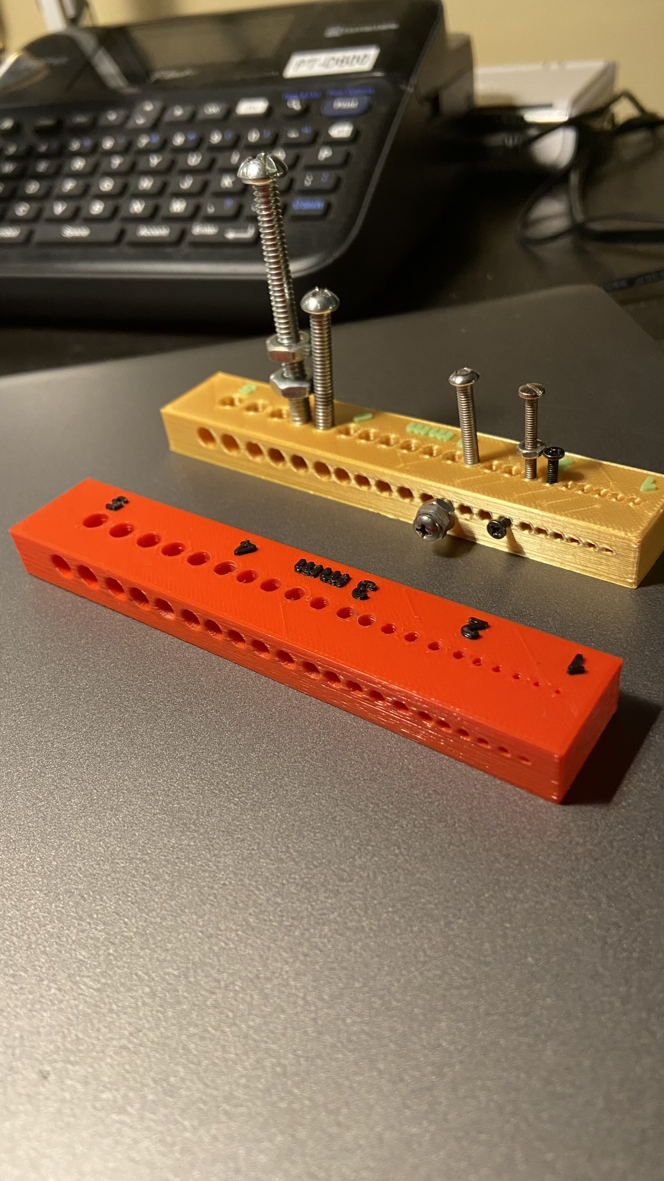
When I first got my Prusa Mk3S and began using FreeCad for small mechanisms, I realized that hole diameters were off a bit. I noticed that vertical (z axis) holes were slightly better than “cross axis holes” (X and Y axes), so I printed this proof block to test fit various machine threads, both metric and imperial:
The block has both vertical and cross-axis holes from 1 mm to 5 mm, every 0.2 mm. For each thread size, it simplified picking FreeCad diameters for (1) loose clearance, (2) tight clearance, (3) easy self tap by the machine screw, and (4) tight tap (run a tap through before assembly). This block should be printed with the same nozzle and extrusion diameters as the target print. For my purposes I use a 0.4 mm nozzle and 0.2 layer height. .stl attached: Holes-Block with Holes.stl (1.3 MB)
Thanks Jack, but if the X and Y are off a bit as you say then both the ID and OD would be out (?). I still feel that the problem must be something with the filament (differential shrinkage, or something like that) or the extruder. The filaments are flattened and so there is anisotropy in the Z direction compared to the X-Y, perhaps that’s why horizontal holes/threads a different to vertical ones?
I think we are using the term “calibrate” differently.
Calibrating a 3D printer starts by calibrating the extruder itself:
Then calibration moves to fine tuning the extruder AND the slicer, the flow rate.
Third you want to look at your infill setting of your slicer(Print Settings->Advanced) because too much infill will push your inside-object perimeters around as in pushing an ID hole in the object to be smaller as the infill pushes on the “perimeters” of the ID hole as the plastic is extruded and cooled.
Once you have done these 3 ‘calibrations’ you should be down to tweeking for fit in the .1mm or less range. But being aware of things like speeding up your machine will change your results since going too fast will “pull” on the extruded hot plastic and make a thinner perimeter and therefore the adjacent line will not adhere well to the previous perimeter. There will be a sweet spot for your hotend and extruder which will handle different colors well so you don’t have to tweak your extruder multiplier to compensate for variations in density and viscosity.
The other two standard 3DP rules for setting up the slicer is not to print perimeters less than the width of your nozzle diameter and no layer thicker than 80% of your nozzle diameter.
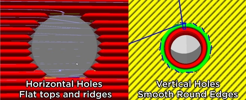
As you probably know, the variations you see between vertical holes and horizontal holes are because the slicer has to start and stop perimeters on the horizontal holes and so there is the extrusions rounded ends to compensate for AND your retraction capabilities also come into play as the pressure in the nozzle will be released as the extruder is stopped and moved to the next position.
On vertical holes there is a continuous extrusion motion and then a very slight move to the next perimeter.
And for accurate holes you always want to print the inside perimeters first. The reason being the first perimeter will be the most accurate and hopefully get a little bit of time to cool and solidify before the adjacent perimeter is put down. That 2nd perimeter will put pressure on the side of the previous perimeter as the rounded extrusion’s gaps are filled with the plastic from the next perimeter.
When I said that I calibrated X, Y, Z and E. What I meant is I calibrated the X, Y, Z and E STEPS per mm.
But it never occurred to me (perhaps it should have) that I still need to calibrate the flowrate after that, and so I’ve never done it. I will be taking your advice and doing that soon to see if that makes a difference to this inner dimension/outer dimension problem. Even if it doesn’t at least I will know that the printer is behaving precisely as intended.
I have also learnt that it may pay to keep a few different Slic3r filament profiles for all of the differently colored filaments that I use.
For me it was a two-step process: (1) make the printer as good as it could be for my chosen layer height, with reasonable effort, then (2) make the parts that I’m printing as good as they need to be for my intended purposes. My hole diameter gauge block really just addresses the second step in my process. When you think about it, even a Bridgeport milling machine in a classic machine shop does not produce a “perfect” part from a CAD drawing. It’s all about acceptable tolerances.
Jorge…Thanks for starting this discussion–good to see that others are thinking about such matters too. And thanks to the rest of you for your insightful inputs…Jack