I don’t think you realize how many settings there are because that would be a lot of screen shots. I’m just packing up a couple( fast and faster ) versions of the config bundles I’ve used. You must understand that this is also for a particular PLA roll, having a dark color(green) and calibrated for it so you will have to measure your filament diameter, calibrate the temp setting and set your extruder multiplier based on calibrated results.
My Ender 3 is an original. It was purchased in 2018 or 2017 an a price of under $200 so I couldn’t pass it up. But I left it in the box until around March of 2020 when Covid was starting to hit the US hard and healthcare PPE was nowhere to be found and I needed another printer to help local healthcare workers.
I agree - copying someone else’s settings may not be the best idea… I was dismayed at the fact that - after following Doug’s advice, my prints of parts that I have printed before are actually coming out looking pretty awful compared to parts that I have printed before, and the/inner outer diameter issue has not gone away - even though my single perimeter prints are now spot on. The parts are coming out with zits and blobs everywhere even though I am retracting 5 mm on every layer change.
Then I looked at the box of (new) filament that I had been using - PLA+ not PLA (bought on-line assuming its PLA), The manufacturer of this PLA+ recommends a higher extrusion temperature 220-235 degrees C and platter heating - 75 degrees C.
I have not tested this, but the pigments are likely to have an effect on the extrusion properties of the filaments. The white in white filament is Titanium Dioxide, black is probably carbon black. these additives are likely to have effect on the extrusion properties too - which means that you have to have a different filament profile for every different color of filament even if it’s the same material and nominal dimension.
As mentioned before, these things don’t normally affect figurines, etc… but when you want your 3D printed threads to fit - say - a standard bolt, then you are constantly wondering where that extra 0.01 of a mm came from. I can compensate for holes in FreeCAD easily enough, but threads…
Happy 3D printing everyone… I think I might stick to woodwork!
But when you stick with a good filament vendor then your Filament settings you’ve saved for different colors will generally be close or spot-on.
And another way people get around issues with threads and holes shrinking is by using metal inserts. Very easy to install and hole diameter isn’t so big a deal when you’re melting your way into the part.
I’ve never tried tapping a hole in wood but I have seen wooden threaded holes and threaded bolts but they are WAY bigger than 2mm, 4mm or 6mm in diameter.
Oh, yeah, PLA+ / PLAPro I’ve always seen wanting higher print temperature. I could see that being a lot like my recent hotend frustration where I wasn’t printing at the temperature I thought I was…
viscosity is a big deal in FFF and it is part of calibrating but very much more when you are looking to find the maximum speeds. On my delta with 250mm/s moves and 125mm/s printing I had to accept a little bit of stringing because you have to run on the hotter side to move that much plastic through the hotend and keep a stable temperature.
I think companies like Makerbot and Prusa like to sell their own filament which they rigorously test and validate for properties for which all colors and types work within a narrow range of options/settings. I’d gladly pay the extra $5-$10 more for a consistent filament source. But even then you have to be careful. I once found MicroCenter had great filament prices and the filament was consistent after a couple of rolls I then purchased maybe 10 rolls. A couple of years later I purchased the same brand from MicroCenter and it was crap. The only 3D printer it would work ok in was my old Makerbot Replicator which runs slow and steady.
No, no! I’ve been making hubs for the feed rollers of a thickness sander that I would like to eventually use to sand the tops of ukuleles and perhaps a lute or two. The axle of this DIY machine is a M12 threaded rod. and the threaded hubs that I have been printing as M12 have to be precise both in outer diameter (to fit inside a long cylinder) and on the thread - to screw onto the threaded rod.
It’s OK. Woodwork has its frustrations too even though the tolerances are not as tight. Figuring these things out is what keeps us doing it right?
Agree about paying extra, if it guarantees the quality and consistency. In fact, I bought the PLA+ from a reputable retailer in AU.
But I am a bit more skeptical than you are about name brands products being more vigorously tested. In Australia all of this stuff comes from one or two places in China. That does not mean that its bad quality, it means that there is very little difference between “no name” and brand names. There are some exceptions… I thought that all PVA glues are created equal, until I used a particular PVA glue made in the USA, but this glue is available only in specialty stores - or you have to get it on e-BAY from an overseas source. (Not sure if we are allowed to say Brand names in this forum).
In the end It’s very hard to say whether the extra $$$ will translate to better quality - So I kind of aim for the middle.
Even when I’m cutting metal with precision machine tools, a thread isn’t a precision locating device. If I need precision, I’ll use a mating fixture and hold it in place with a screw. That could be a taper, or a bearing seat, or a bushing, but a screw just isn’t particularly precise.
I would expect that clearing printed threads with a tap would maintain as much precision as you have with a print, and give you more surface engagement with the thread than you would have with layer lines throughout a print with enough internal clearance to thread onto the rod.
Do you have an indicator that you can use to measure runout of your setup?
Big picture: You are suggesting using PLA in a hub for a sander. You do you, as they say, but some things to keep in mind:
PLA gets soft at a rather low temperature, and sanding gets hot. While the belt can cool as it runs, some of the cooling will be into the drum, and the heat has nowhere to go from the drum, so the drum will probably get warm. There’s a reasonable chance that in extended operation you’ll end up with the drum getting warm enough that the PLA gets a little soft, and it won’t take getting very soft to suddenly deform.
PLA creeps or permanently deforms under pressure. If you keep the sander loaded when it is not in use, you’ll probably come back to a lopsided drum even without the heat problem.
PLA can be changed to a much harder, higher-melting-point substance with heat treatment. (This is sometimes inaccurately described as annealing, but it’s actually the opposite ot annealing.) Printed, if you leave it in a car in the sun it will droop into a puddle; I’ve read of someone heat-treating PLA and successfully making a handle for a kettle that doesn’t get soft when boiling water in the kettle! However, this heat treatment process causes anisotropic distortion; it distorts differently along Z (as printed) from X and Y. It is not a precision process.
I don’t have access to a lathe. I tried to widen 12 mm holes that needed to be perfectly centered in the hub using a drill press. But doing that made the hole acentric, so I have avoided doing that since. I don’t have the 12 mm tap that matches this threaded rod, so I trying to get precision off the 3D printer. As it turns out - FreeCAD is excellent at drawing standard threads, and you can specify a tolerance of sorts, which alleviates the problem I originally described.
I’m getting there. My latest threads are going on the M12. They are a bit tight, but that may be a good thing.
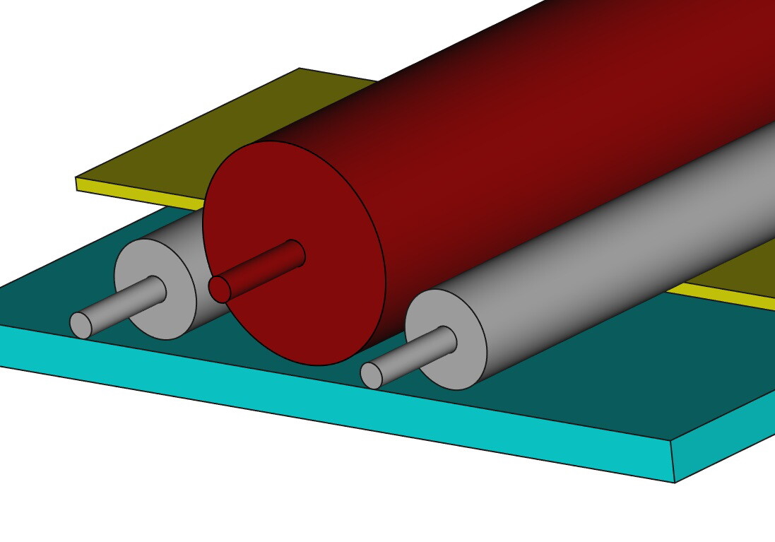
Not well annotated but the above is what I am building… The big cylinder (red) is 100 mm in diameter and is supported by 4 evenly spaced 96 mm PLA hubs (original post) inside the cylinder which take a 12 mm shaft. You may now understand that the holes in the hubs need to be precisely 12 mm and precisely centered, and the OD of the hubs need to be round and precisely 96 mm in diameter.
The large cylinder is driven by a 3/4HP motor and a pulley arrangement that reduces the speed but increases the torque. I can confirm that this arrangement is working well. There is not a great deal of heating.
The work (yellow) is fed underneath the sanding drum and only a fraction of a mm is sanded off at each pass. But without the support of either a conveyor or some in/outfeed rollers it’s difficult to stop the work from being pulled under and shooting out the other side. Also, if the work is not fed in evenly the sanded surface will come out rippled.
Therefore, I am currently building the in-feed and out-feed rollers. They consist of 2 lengths of 50 mm PVC pipe covered in rubber with a 12 mm threaded rod axle through perhaps 4 or 5 PLA printed hubs evenly spaced within each PVC pipe. The rollers will be driven by geared DC motors.
The advantage of the feed and outfeed rollers over a conveyor belt (like the ones that commercial machines have) is that the rollers will hold the thin veneers flat as they pass under the sanding cylinder.
I know what you are thinking. Only the most foolish of Makers would tackle such a job, but I think (well, hope) that it will work… I am hoping to build on the success of the sanding cylinder, and if it fails, I can always use the rubber coated PVC in/out feed rollers as the driving mechanism for a conventional conveyor belt. When done, the whole machine should only have cost me 3 times as much as commercially available machine ;-). But I will have had 10 X as much fun building it.
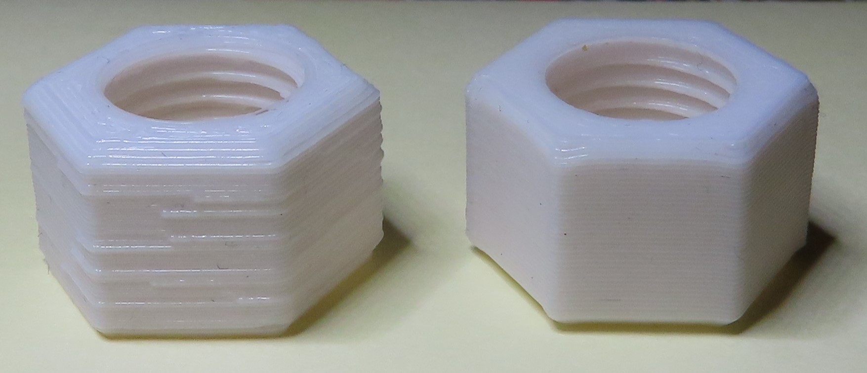
Things were getting out of hand so I went back to Slic3r - specified 0.3 mm layer heights, and told it that the Filament Multiplier is 0.8 as previously calibrated - I left the different printing widths at either auto or default.
It seems that the print quality using the “sane default” extrusion widths that Slic3r calculates (Picture Right) is much better than the print quality using the 0.45 mm extrusion widths I was specifying in Prusa (Picture Left). I guess that the Prussa defaults would be equally good. As I said, I learnt a lot.
The one on the left is not calibrated / tuned properly as no way is that an acceptable result. Something or somethings are not right. For one, a 0.8 ( 80% ) for the extrusion multiplier is crazy out of spec which is another indication something is not right. The extruder multiplier is typically fine tuning in the hundredths and thousandths of a percentage point or maybe 1% at most. Had you noticed for one of my filament settings in the config bundles the filament diameter was 1.77 instead of 1.75? That too is part of the calculations involved in making a consistent plastic track of plastic.
Also, I would never print at .3mm with a .4mm nozzle unless it was for testing purposes and/or the object wasn’t needed precision elements like holes, etc. I did it for the PPE since they were for visor/face shields to fit onto the head(flex fit) and punch hole clear sheets split across 3 or 4 pins on the visor. .2mm layer height or less for anything needed accuracy and for strength I will sometimes tilt the object so the layer lines are not in the shear plane.
Maybe you can try the Simplify3D slicer as I’ve seen it has some nice defaults and I’ve seen people use it with a variety of designs with good success.
It’s the only way I could get the 0.45 mm widths to print on spec on the single perimeter calibrators. I don’t remember now what my layer height setting was when I printed the calibrators, I THINK it was 0.4 or even 0.45 - maybe the printer/slicer can’t cope with 0.45 width and height?
Doug, note that 0.3mm is my layer height not the layer width. 7 days ago you sent us a screen shot of your extrusion width settings (0.45 mm for the most part). What are your layer height settings when you use those width settings? A couple of days later you said that you have set the layer height as low as 0.2 mm. Slic3r defaults to a layer height of 0.3mm (the reason I used it) and if I remember right Prusa recommends anything between 0.1 and 0.35 for a 0.4 mm nozzle.
It never rains, it pours I was going to re-run the filament calibrator to check the filament parameter setting again but now my printer is broken! My printer’s nozzle parks at 5 mm, on the top right of the platter after bed levelling before each print. But now it seems that one of my two Z screws is sticking on high-speed return to zero to start the print. I think I might invest some time in dismantling, cleaning and reassembly. It’s been a good tool for making jigs and things.
Sorry I will not be able to get to the bottom of this for a while.
a .4mm nozzle diameter can ONLY print UPTO 80% its diameter for the layer height.
So a .4mm nozzle can not print a .4mm, or worst a .45mm layer.
Again, I stick with .2mm layer heights most of the time and anything above that will get you less quality but faster prints and surely one would not pick low quality modes to do calibrations.
If you want a rule of thumb with .4mm nozzle
.1mm layer height for high detail/fine detail prints, longer overall print time
.2mm layer height for normal/good detail, avg overall print time
.3mm layer height for low detail/coarse detail prints, faster overall print time
.32mm MAX layer height( 80% of .4mm nozzle diameter )
Regarding your Z axis problem, slow your Z speed down if it’s too fast and one of the motors is skipping steps. Also, 3D printers are high resolution machines, they should not be run or left in dusty environments. Also, put a cover over it if not in very clean air environment( dusty, pet hair, etc ).
Duh… Yes, I’ve specified 0.2 or 0.25 for as long as I can remember, until a couple of weeks ago when I started calibrating for the filament multiplier. 0.45x0.45 is a perfectly round extrusion and 0.4x0.45 is not far off it - I should have been obvious that that’s wrong. I can’t explain what I was thinking.
I keep my 3D printer covered when not in use and use it in my spare bedroom. It’s given me years of trouble-free service until now. All of a sudden today, it’s started to print at 5mm (i.e. it’s not making the move from 5mm to 0.3. I keep the Z screws clean and lubricated with a light machine oil. I moved the Z up and down several times and there seemed to be no problem, but that first move is probably made fast and at high acceleration… I disassembled and cleaned the Z screws and adjusted the alignment. But I’m not happy with one of the flexible couplers - I have ordered the parts and will chage both when they arrrive.
And the Common Sense award goes to: Michael K Johnson @mcdanlj !
My last good print was still tight and as you may have gathered my 3D printer is now having a bit of a rest until the Dr arrives. A rummage through my shed revealed a M12x1.75 tap that I thought I did not have. Clearing that thread with the tap is quite a lot easier and far less frustrating than what I have been doing for the past week or so… It only shaved a very small amount off the inner surface but now that nut runs really smooth on the M12 bolt.