Filament (PLA) printer. Discrepancy between precision of ID and OD in same model

When I built my very first 3D printer it was a Mini Kossel but much larger because I needed to be able to print a 6.5" diameter coffee bean grinder bean saver(my invention). I was one of the first to go large with a delta and using 1515 extrusion was a bit light so I had plenty of issues printing once I figured out how to manually calibrate a delta 3D printer running Marlin.

I learned a heck of alot trying to print various test objects to figure out what was wrong and what needed fixing. Went through half a roll of filament before I had it dialed in and I also knew a heck of a lot about Slic3r and calibrations.

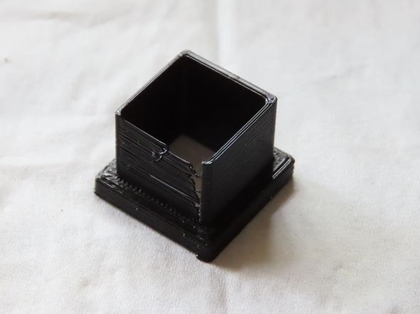
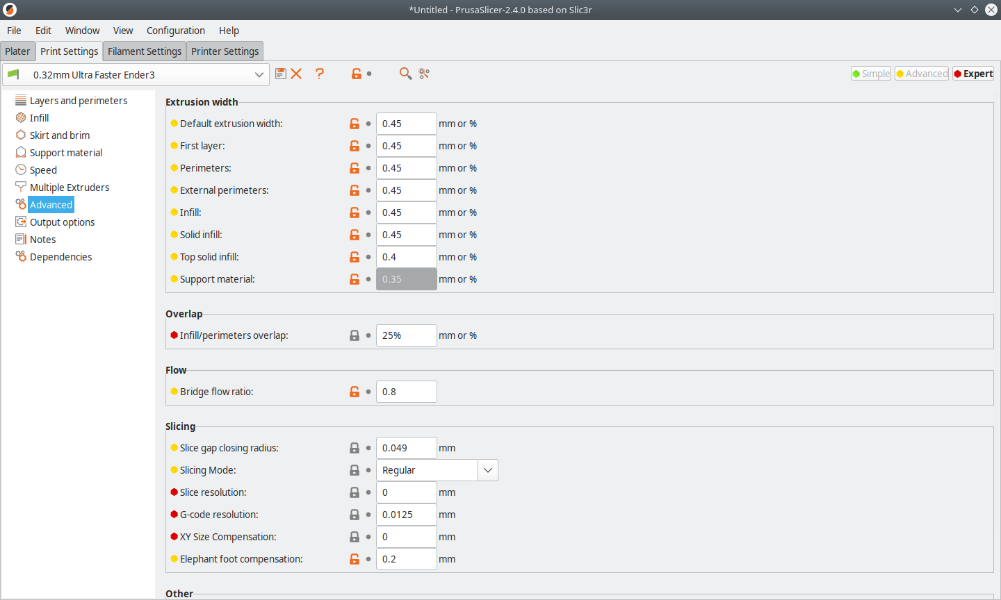
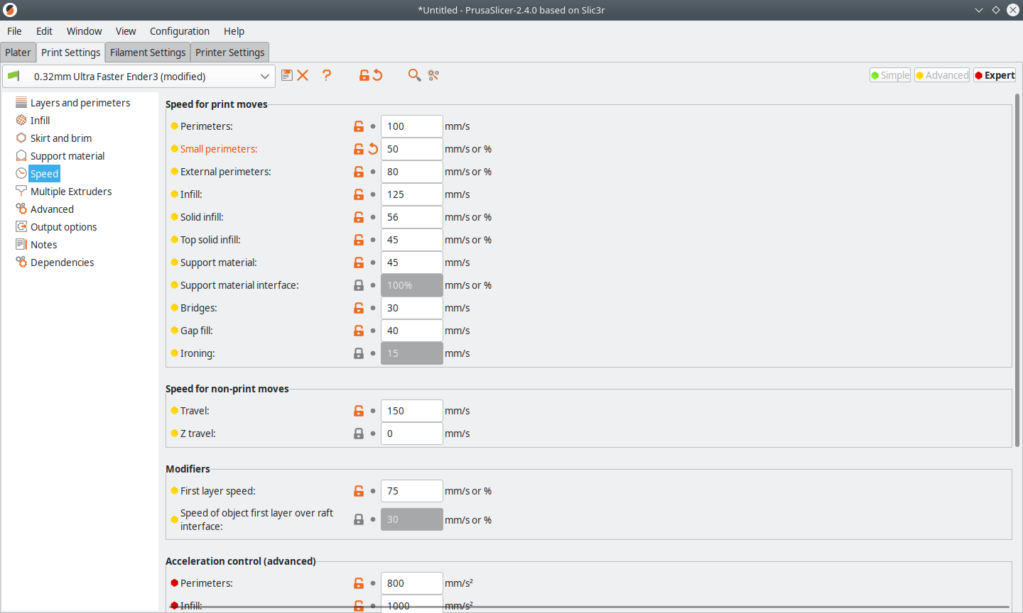
When Covid hit, a nurse in the neighborhood put out a request for 3D printed PPE since they were going a week with one N95 mask and no face shields. So I added an Ender 3 to my 3D printer stable and had 3 printers going 10+ hours a day making different face shield sizes and in order to print as fast as possible I tuned each to their highest speed which still made high quality parts. A guy from the local maker group wanted to help so I gave him files and told him they had to be good quality and he gave me garbage. Stringy, delaminating when flexed, etc so I had to throw them away and told him they were unacceptable. Took him 2 more tries before he was making good parts. Because he also had an Ender 3 I could share my Slic3r settings. He said he had no clue his Ender 3 could make such good parts.

Spend a little time up front and the machine will be reliable and make you good parts. Yup, you might still tweak a Slic3r setting here or there or even tweak the design but itā€™ll be consistent. And every 3D printer should ship with a set of cheap but accurate digital calipers so thereā€™s no eye-balling how things look, you measure and know what youā€™re getting.

$0.02

1 Like

Agreed.

I have an early series Tevo Tarantula. It was a birthday present from my family. Itā€™s a very cheap DIY kit printer but I love it because of the sacrifice, consideration and love that went into its purchase.

On the main my models have not required tight tolerances. Even so I always made sure that the steps/mm in every degree of freedom were always spot on and made sure that the first layer went down on the platter just right. I have always been happy with the look and quality of the prints.

Lately I have been making wood working jigs and machines and I have been using the 3D printer to make some of the components - These sorts of prints involve much tighter tolerances.

I draw the parts in FreeCAD, export to STL and print from Repertier/Slic3r (lots that can go wrong at every step, lots of different settings and parameters in each of the bits of software). The picture I posted early on is a 96 mm hub that fits in a 600 mm long aluminum cylinder for a drum sanding machine that runs on a 12 mm shaft. ie both the 96 and 12 mm have to be precise and accurate. Thatā€™s the first time I noticed that the parts were not printing precisely as I drew them in FreeCAD. By a sort of trial and error I worked out that to get the 96/12 mm, I needed to draw the part in FreeCAD as 96/12.5mm. Thatā€™s two different tolerances on the same part! The only difference is that one is the OD and the other is the ID.

Counter drilling introduces eccentricity and that risked introducing vibrations and wobble.

Anyway, the fudge got me out of trouble and then life overtook me and I never really got to the bottom of the problem. But now I have a need to print M12 threaded 40 mm hubs and so the problem has resurfaced, so I thought I should try to sort it out this time. It will be really cool to know that the parts will turn out exactly as drawn.

2 Likes

I print mostly PLA so when I tell the slicer to print outer perimeters first, the part cooling fan really helps get those perimeters cooled so they get far closer to the expected tolerances than had it printed the perimeters from the inside outward. And a large outer perimeter will cool into place much more than a small ID perimeter. Itā€™s just tough to figure out ways to get the slicer to print each ID perimeter then do something else before printing the 2nd and 3rd ID perimeters.

Iā€™ve had to make 2 of something and spread them out just so the parts had time to cool a bit before the next layer went down. And thereā€™s now a setting in Slic3r which lets you specify the minimum time of a layer so they have time to cool.

3D printing is not like a microwave oven and I doubt it ever will be if you make a wide variety of parts and things.

1 Like

I thought that people who replied would appreciate an update:

(1) I re-calibrated the XYZ and E steps per mm
(2) Using FreeCAD, I drew a 20x20x15 high mm box with 0.4, 0.8, 1.2 and 1.6 mm thick walls (1,2,3 and 4 perimeters respectively). The box sits on a 25.4x25.4x5 mm pedestal. (pictured)

Cube Calibrator.pdf (44.9 KB)

I then exported the FreeCAD parametric drawing to STL using an inbuilt FreeCAD function.

(3) I set the extrudate diameter to 0.4 mm (= nozzle diameter), the filament parameter to 1 and all of the print speeds to ~60% of Slic3r recommended values (i.e. everything nice and easy)

Results:

IMG_0791 (1)

Even though the printer struggled with the single perimeter wall, the wall thicknesses were 0.38, 0.78, 1.19 and 1.64. This is near perfect considering the tough challenge. The ratio between the printed dimension and the drawn dimension was 1.00 for all the dimensions except the 0.4 and 0.8 mm walls.

I was very pleased with this result and concluded that the filament multiplier did not need to change from 1. The result was the same with white filament.

HOWEVER

Just today I drew and printed an array of 5 x 10 mm tall cylinders with 3mm walls: The inner Diameters (ID) are 2, 4, 6, 8 and 10mm the Outer Diameters (OD) are 8, 10, 12, 14 and 16 mm respectively.

While all of the OD were nearly perfect (< 1% out) - every single one of the ID were 5% undersize.

So - even though my printer is perfectly calibrated, produce perfect cubes and filament thicknesses, when printing a cylinder either the ID or OD will be out with respect to how it was drawn.

Iā€™ll now explore the possibility that FreeCAD is creating the STLs of the inner surface of holes incorrectly, whether Slicer is creating the GCODE properly.

Iā€™ll try another Slicer and CAD software and see if the problem persists. At least now I know home much larger need to be drawn to print correctly.

J

I would expect it to be undersized since your previous design showed that it was under extruding by a couple of hundredths of a mm. And that .4mm wall was hideous and IMO unacceptable as it was not even a complete wall.

I generally have a few different calibration objects having a single size well thickness so I can watch not only the corners but how the motion is in all 4 directions. Instead of one object with different thickness walls. You also want to know if thereā€™s any looseness in your mechanical system and you canā€™t tell that as well when you change the motion(more or less perimeters on each side).

Iā€™ve attached 2 calibration objects I use on my .4mm nozzle machines. The walls are .45mm thick and the slicer must be set to that it only prints a single wall. The squares-in-squares object is both for making sure Iā€™m getting .45mm wide walls at different speeds(longer walls have more room for acceleration) but also basic retraction settings so that thereā€™s no bulging when the hotend moves from one wall to the next and also so thereā€™s no gaps in the walls .

The thing wall object with holes is where I really tune the retraction so that the horizontal holes are clean, no strings and very little bulging as the retraction re-primes the hot end.

And I will always error on the side of slight over extrusion when accepting the wall thickness but I calibrate to the thousandths position, not hundreds of a mm. Any under extrusion will result in off spec and weaker parts while over extrusion gets you slightly off spec solidly built parts.

Hereā€™s how I set my Prusa Slicer settings for my Ender 3. Iā€™ve been setting my own extruder preferences for years since I was not happy with Slic3r defaults when just setting the hotend extruder diameter. I use .45mm because FFF extruders work well when there is pressure at the nozzle end and you donā€™t get much pressure built up when you try to extrude a .4mm line out of a .4mm hole.

You might find this helpful too:

calibration-squares-in-squares4_5.stl (31.8 KB)
Retraction_square_wHoles_45.stl (129.3 KB)

1 Like

Hi Doug,

Thanks for persevering. I agree that that single perimeter wall is hideous, but I put it down to the Slic3r putting the start of each layer on that corner (even though the seam position is set to random) and having filament cooling on at all times. I have always used Slic3r.

You have given me a lot of information and I must admit that I donā€™t fully understand all of itā€¦ I think that changing the filament multiplier on the basis of that 0.4mm single perimeter wall thickness is not the correct thing to do, because I would not specify a single filament wall in any other model that I print and because the dimensions of the 1.2 mm (3 perimeter) wall were spot on. Thatā€™s partly the reason why in the subsequently printed cylinder calibrator/tolerance plate I specified 3 perimeters and made sure that the cylinders were of a sufficient thickness to require infill.

Iā€™ll try to follow your suggestions just to see what happens, but in my mind none of it explains why the diameters of round holes in the parts that I 3D print are as much as 5% too small in diameter while every other dimension even the outer diameter of rods or cylinders in even the same part is pretty much as drawn in the CAD model (no more than 1% out and often much less).

I feel that I may be flogging a dead horse, and that the explanation is much more likely to be in the way that FreeCAD is generating STLs in the diameter of cylindrical holes or in the way that the Slicer is generating the GCODE for those parts.

Anyway, all this has taken me away from woodwork for far too long! :wink: Thank you for your help. I have not given up completely and if I do anymore on this, Iā€™ll post again so that others can learn from it.

Warm regards

Jorge

doesnā€™t matter, calibration should be such that when you ask for a single wall you get a single wall.
No if ands or buts. Otherwise, youā€™re not going to get good parts.

If youā€™re doing Disney figurines then you can get away with poor calibration and just fix stuff up in post with either epoxy or acetone vapor bath.

every model you ask your 3D printer to make must make a single track so if your tracks are not being layed down as the slicer expects them to then you wonā€™t get solid models. The reason why you get close when you put down 3 perimeters is that the center of each is where it is supposed to be but the problem is the intersection of the 2 / 3 walls. They are not meeting correctly. If you tracks were only getting put down at .3mm wide and you made a 3 perimeter wall the outside dimensions would be only off by .1mm( .05mm x 2 ) instead of the 1mm x 3 youā€™d expect.

With under extrusion I would expect the inside diameters to be too large but you are saying you got the inside dimension too small even though you were under extruding? That doesnā€™t make sense unless something else is at play. Printing too fast and pulling on the extruded track and also you have very little pressure at your hot end because you have a .4mm nozzle and everything is trying to make a .4mm track of plastic. Look at the link I send where thereā€™s a picture of the hotend nozzle and how the molten plastic bulges beyond the hole diameter. You must have pressure in the hotend or your layers wonā€™t stick together well, your tacks will pull off the previous layer or pull with the hotend.

The RepRap guys, the ones who started this whole DIY 3D printer craze took only a year or so making the machine but it took about 3 years to learn how to make the hotend work and the magic sauce was constant pressure from the extruder motor/gears and constant pressure inside the hotend as the plastic was extruded out the nozzle.

1 Like

Update:

Increased the extrusion width to 0.45 mm (NB: nozzle diameter = 0.40 mm. Increased the filament parameter to 1.05 as determined by the printed single perimeter wall width divided by the specified wall width. I found it difficult to measure the single perimeter width on Dougā€™s calibration squares in squares but they were very close to 0.45.

I decided to make my own single perimeter calibrator this one is a 10mm cylinder inside a 30mm cylinder inside a 40mm square. The walls are 10 mm high for ease of measurement. I actually got a very good looking print! The layers are well formed and strongly bonded with not a sign of imperfections the wall thickness is spot on 0.45 as drawn. There is a lot of ā€œelephant footingā€ and the first layer seems a little crowded. nothing that a good first layer offset wonā€™t cure.

BUT: the 2ID 6OD, 4ID 8ODā€¦, 10 ID 16OD, cylinder ā€œcompliance plateā€ I mentioned earlier is considerably worse with respect to undersized hole diameters. Every hole seems to be out by over one half of a mm, that is I cannot fit a 9.5 mm drill bit into the hole that I drew as 10 mm, and so on right down to 2 mm. Again, the error appears to be systemic, not random.

I am not going to pursue calibration as an issue any longer and I will be returning to lower diameter extrusion widths as I feel they gave a better more looking more consistent print. (Sorry Doug, I tried to verify your theory, but experience is king and the results are clear. The discrepancy with the inside diameter tolerance is not caused by extrusion thickness or under - extrusion.

I might look at this some other time. I am a bit frustrated with the problem now. Thank you who took time to reply.

Jorge

.5mm or less hole shrink is considered acceptable and normal. Iā€™d lost track of your original post which stated you were seeing only .2mm shrinkageā€¦ You might get that a bit lower by setting the slicer to print external perimeters first AND greatly slowing down the external perimeter speed. At play is material shrinkage and the same effect as which causes cars to need a differential to drive the wheels, ie outer diameter of the trace is longer than the inner diameter trace. Notice in Prusa Slicer there is a setting for speed specifically for small diameter holes but yes, you will only get so close to the design of small diameter ID holes. Also make sure your polyline count is high for those designs with small ID holes.

FYI, these settings are for an Ender3 with Hatchbox PLA which I calibrated to produce engineering quality results for PPE manufacturing during the early months of the pandemic. A local nurse was providing 3D printed PPE to local hospitals(including her own) while they had none. I had 3 3D printers operating almost 12 hours/day for about 2 months.

1 Like

Note that extrusion width less than nozzle hole diameter will consistently provide terrible results. Extrusion width should generally be meaningfully larger than nozzle hole diameter.

I learned all about this by a typo once. :relaxed:

1 Like

ā€œNote that extrusion width less than nozzle hole diameter will consistently provide terrible results.ā€

By what objective measure, Michael?, I ask because that has not been my experience. The ā€œterrible printā€ I posted previously was generated using 0.40 filament diameter on a 0.40 mm nozzle. And the problem that I described in my original post is now much worse that I started printing with an extrusion size of 0.45mm on a 0.4mm nozzle. I feel that the few prints that I produced using these settings are not as good as when the filament was set to 0.25 mm.

Itā€™s essentially impossible for it to be accurate, as far as I can tell, and supported by my recollection of my gestalt of what Iā€™ve seen others post about it. Iā€™m struggling to understand a physical model in which an accurate print would be possible trying to extrude a bead that is narrower than the nozzle it is coming out of. How would that even work? What establishes the location of the edges without that constraint? I know I could be missing something, but I donā€™t understand what it would be. :confused:

If the filament coming out of the nozzle is basically forming an hourglass shape, wouldnā€™t it tend to round over corners and leave voids?

Certainly, when I by a typo accidentally told my slicer to extrude a narrower bead than my nozzle width, it looked underextruded, and was filled with voids, did not adhere well, and was generally structurally unsound. Took a few prints with me cleaning imaginary clogs from the nozzle before I noticed the problem in the slicer setting, fixed it, and resolved the problem.

But you say ā€œfilament was set to 0.25 mmā€ so Iā€™m wondering whether weā€™re actually talking about the same setting. What Iā€™m talking about isnā€™t a filament setting.

I admit that I donā€™t know every prusa-slicer feature by heart, so maybe they have a setting for thisā€¦ Or cura.

Iā€™m not making this up and Iā€™ve seen it stated and analyzed many times over the past 10 years just as it states in this link I had provided previously: The effect of Extrusion Width on Strength and Quality of 3D prints ā€” CNC Kitchen

3D printing seems to be part voodoo but itā€™s not and itā€™s been used for 40 years so the processess are well defined. When going offscript one method might seem to work for one model might not work for another model. And when you said youā€™d set your Printer Setting - Advanced settings as I had for .45mm extrusion widths, you didnā€™t ask what the Extruder setting was in the Printer Settings. FYI, it is set to .4mm and I donā€™t know why you could not measure the wall thickness of the squares in squares model I provided since it should print over 5 layers and you only need to measure the wall widths of the top 3 or so layers. Any functional calipers will do this as long as they have not been damaged and at which point they shoujld be thrown away. Calilipers are cheap these days and yet they still measure accurately from top to inside the jaws. I use the tip to measure the wall thickness. And you must wait until the plastic cools.

When Iā€™ve calibrated I change my extruder multiplier 3-5 times before I get close to an accurate model. So I was surprised you only changed yours once and found the .450mm wall thickness. Lucky I guess.

As for the slicer, I was using Slic3r for 5 or 6 years after evaluating it along with Cura and the default for Pronterface. Prusa uses Slic3r and is very active in developing it and feeds changes back to Slic3r but I found Prusa a bit ahead of the curve and switched. Itā€™s still Slic3r under the hood and still has tons of settings which can be tuned to make good parts as long as you are in Expert mode and all those settings are exposed.

If you look at the Print Setting->Speed you will see a setting for Small perimeters and while I had mine set to 30mm/s the default is 15mm/s and I too once used percentages for many settings but found things were not linear as filament density varied(due to color pigments) and elasticity and viscocity varied enough that I have saved config settings for different color filament even from the same vendor.

Sounds like you are happy with under extruding and using extrusion widths well below the nozzle diameter. If youā€™re getting acceptable prints thatā€™s great, we can just provide the why thatā€™s not done in the industry and some of the reasons why. Keep on making stuff.

1 Like

Iā€™m confident that I was substantially undersized when I ran into this. I was almost certainly printing in PETG and I wonder if the workable extrusion widths for a nozzle are way different with PLA?

It has everything to do with being able to create and maintain a constant pressure so that the extruded plastic is the same width, a width the slicer expects and created the gcode based on. With a smaller extrusion width you will only have the back side of the nozzle relative to motion which is compressing the extruded plastic and nothing holding back pressure in the hotend chamber. But it might work in some situations, speeds, settings but for a wide variety of designs and speeds a pressurized hotend is needed. Thereā€™s even been work to try and measure the pressure.

Doug, Michael

So this is me eating humble pie:

In trying to explore this further today, I created Calibrator things with 0.25, 0.4 and 0.45mm walls. As I said in an earlier post, I have now changed to Prussa and enabled the Advanced Settings which provide controls over the extrusion widths of the different parts of the prints (perimeters, fill, etc.). I also specified a 0.40 mm nozzle. I set all of the extrusion widths to 0.25 and tried to slice the 0.25mm walled calibrator ā€œthingā€. Prussa wouldnā€™t have a bar of it! Prussa returned an error telling me that the extrusion widths were too thin and aborted the slice.

It seems that what I was previously changing in Slic3r was the LAYER HEIGHT not the extrusion width. Slic3r does not have a separate setting for extrusion width (at least none that I can see) - Slic3r was probably keeping the extrusion width to some default value based on the nozzle width.

Knowing this, I will now concentrate on getting my 0.4 mm part just right, and tweaking the extrusion widths, flow rate etc, so that the precision of inner perimeters is as good as it can be. Dougs earlier posts will be valuable.

Iā€™ve deleted some of my earlier posts so that they do not lead anyone astray.

Regards

Jorge

2 Likes

I just loaded Slic3r 1.30 and it has the same or very similar extrusion width overrides in Print Settings->Advanced menu. The Print Settings / Filament / Printer Settings donā€™t show up as tabs next to the Plater tab in the GUI but if you click on the gear icon next to the configuration selections to the right of the Plater window you will get those options similar to what you see in Prusa Slicer.

But Iā€™ve been sold on Prusa Slicer for a few years now and because it is based off the Slic3r codebase it has all these wonderful options to find and try to figure out what the heck they do. :wink:
I literally spent 3 months going them many of them while trying to figure out how to get an oversized custom made Mini Kossel 3D printer cranking out parts which could be used to make another Mini Kossel.

Speaking of layer height, what I like about the Prusa Slicer is that while I default to .2mm layer height when I have features I want really well defined I will turn on Variable Layer Height option and gradually shift these features to 0.05mm layers. It can add lots of time to the print but it also can add some quality to areas where features like excessive overhangs and vertical holes generally get a bit coarse at .2mm layers. Something for you to find and play with at a later time.

2 Likes

Yeah, I have looked again as well and found them in Slic3r. Iā€™ll be keeping Prussa as well.I found another setting that may make a difference Advanced>Slicing> Slice/Gcode resolution and XY compensation. I might play with those a bitā€¦

I suppose 3D printing has always been a means to an end rather than an end in itself. I was pleased with the prints until I needed (wanted, really) sub mm precision.

Tried again with the correct filament settings the 0.40 mm perimeters printed 0.39 - 0.41 (my verniers are good to 0.01 mm) and the dimensions of the square and cylinder were good to about 0.10. The print itself was pretty good as well - a few blobs and dibs, but I think that that may be white PLA using.

The compliance plate I printed this afternoon showed that my rods/shafts are good to 0.1 mm or less, but holes continue to print 0.4 to 0.6 mm undersized. But there were adhesion problems with this part (I was getting lazy). Iā€™ll keep playing for clean prints and then compensate for the undersized holes in FreeCAD.

1 Like

Doug,
I would like Screenshots of all your Prusa Slicer configs to your Ender3ā€¦ Iā€™ve read many of your posts and also Iā€™m interested in moving from Cura.
This has been a good post to read for meā€¦ Although I make a lot of bracket and mount with my printer, Iā€™ve always expected my hole IDs to be undersized, But it is common to adjust the drawing to compensate. Myself, I use Fusion 360 to create and adjust parts.