I had asked this in a personal communication, since I felt kind of dumb not being able to find a answer on my own searching the internet. It was suggested I post it here. Thanks
I use and understand how to make LED or solid state devices produce variances in intensity via PWM. LEDs will operate fine at 1% PWM, not a CO2 device at 1%.
The problem I have with relating that explanation to what I’m used to is that a CO2 laser is a continuous wave (CW) device and cannot be cycled quickly enough (due to physics) to produce a change in intensity required by these machines. I guess I’m asking how the hardware modulates the laser beam.
I’ve been over the schematics of the controllers’ power supplies that are used in the small cnc machines and solid state lasers, so I know how they work. I’ve been searching for a K40 type control board and schematic so I can better understand what’s going on with these animals.
The only thing left is control via voltage/current combinations. Do controller boards do this by limiting current/voltage resulting in a lower output? Are the power supplies current/voltage controllable? I’m either not googling the right things or ? Who’s controlling what at the hardware level to make this happen…?
Another thing is the current/wattage have lots of threads, but nowhere does anyone say anything about the voltage. Seems that it would be difficult to know wattage without voltage. I took a rough guess and assumed it to be around 2.6kv, 40 watts / 15 ma. Yet all I see for power supplies are labeled “220 to cathode 220 to anode” I see no high voltage supplies advertised. I do find Chinese connectors advertised for tube lasers that have the appearance of HV connectors. I must be more confused than ever, I think… Or looking in the wrong place…
I will do my best to answer these in the context of a K40, that said most CO2 systems work essentially the same way.
The common way CO2 lasers are controlled is by PWM. Although other configurations are possible the most popular way is for a potentiometer to control the base power of the laser power supply by adjusting its internal PWM. On top of the base power setting by the pot, the “L” control signal from the image controller controls the on/off period of the laser also using PWM. The controller assigns a PWM value and an on/off state to each dot to be imaged. Essentially the controller modifies the laser power by the length of time the laser is on for one dot period.
CW CO2 lasers do have a delay time to turn on but I have never been able to measure it accurately nor found any credible reference to that characteristic. My math model says the time the beam must switch on is clearly shorter than I think a CO2’s laser can switch.
Then again it does work, in fact much better than I think it should ??? I think this is why these machines have a difficult time with high-resolution engraving.
Powering CO2 and diode lasers are two entirely different beasts.
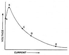
Co2 lasers require very high voltage power with simple to no control of the current. CO2 lasers are gas discharge (negative resistance) so they output very high voltages until the ionization potential is reached, then the device discharges and the voltage drops dramatically while the current ramps. These supplies are by no means standard power supply designs, are dangerous, and notoriously unreliable due to the high voltages.
Negative Resistance
Laser diodes require low voltage but very accurate current control. These supplies are relatively standard in the industry. Note that small changes in supply characteristics can easily destroy a diode.
I have schematics of LPS’s for the K40 but not the controller. In regard to laser power control it’s not necessary to understand the controller as it simply turns on the LPS proportional to the amount of power needed to image a dot. This is done with the “L” signal.
Controllers do not control voltage or current in the laser or the laser power supply. The power is controlled by PWM, i.e. the LPS is fired (enabled) for a % of the dot time (DF) proportional to the power needed. The only physical connection between the LPS and a controller is a digital PWM signal.
Bottom line CW CO2 lasers are controlled by turning them on/of for an amount of time proportional to the amount of power needed to image.
A CO2 laser’s voltage needs are proportional to the length of the tube. A 40W laser needs ionizing voltages in the range of 14,000- 20,000V and typical run currents are 15-20ma.
40 watts is the optical power, not the electrical power. CO2 lasers are highly inefficient (electrically).
Did the math once but don’t recall the actual values. It’s a complex question because the V vs I discharge curve of a negative resistance device is complex. I haven’t found much value in getting an accurate electrical power measurement.
Consider that every time the L signal is asserted by the controller the laser discharges in this fashion.
The importance of the laser current VS pot setting cannot be understated. This is the characteristic curve for the laser tube.
Clearly, these lasers do not run on 220V. This may be confusing the input voltage on the LPS with its operational anode voltage. 40-watt tubes anode runs @ 14 - 20KVDC.
Since the power to these tubes is very high at relatively high current they require special High voltage connections and wiring considerations for operation and safety.
I would very much like to see the LPS schematic. Been in amateur radio since the 70’s, few transmitters at home were not based on ‘valves.’ Didn’t give a thought to how high the potential must get before it actually ionizes. The LPS schematic probably would give me a good idea of how the PWM signal is used to modulate the laser.
I did not understand that you could switch them on and off as quickly as it seems. I’ve worked around lots of equipment and really can’t think of much that isn’t specified as ‘input power’. So that’s a need to know.
Still digesting, but wanted to say thanks for the time and trouble educating me. I’m sure I’ll have more questions when I wake up… Past my bedtime, can’t hardly type…
The PWM inside the power supply (the schematic you asked for) does not modulate the laser. The LPS PWM sets the base power level.
I think of it this way, the PWM in the LPS sets a max power level, let’s say 15 ma. This means that when the LPS is turned on it will output a max of 15 ma.
The controller decides is wants to image a dot at 50% power. It turns the LPS on for 50% of a dot time. This means that the laser is on at 15ma for 1/2 a **dot time. Therefore the effective laser drive is 15 ma .5 = 7.5 ma.
** a dot time is a fraction of the charidege speed proportional to the desired imaging resolution
The controller’s PWM is what modulates the laser not the LPS power control. The laser power supply is turned on-off by the controller consistent with the dot pattern the controller wants to image.
I was skeptical of response time when I first started using a k40 but turns out it does image satisfactorily. I started a project to dynamically measure the optical response but never found a practical and reasonable cost way to make high-speed measurements looking up the business end of a CO2 laser.
Thanks so much. This answers a myriad of questions. And as usual, adds a bunch more… Spent time on the tl494 which controls the LPS… Lots to figure out… Thanks
Yes, looked at the schematic(s). It helps a lot. Been going over the functionality of the tl494. Thanks so much.
I will check out Don’s stuff, have it up and bookmarked…
Thanks for the time to put this together, it really helps. I found my way through the schematic as best as possible, again thanks.
Have ordered a 60 watt model at an incredibly low price. Last chinese ‘deal’ like this cost me $80 for a two bit coin purse…:*(
This is from a reputable site, so hoping for a better outcome.
I do not expect it to have a milliamp meter and have ordered a Mahoney watt meter to keep tabs on output power. I don’t know the length of the tube, if and when it gets here so I’ll wait to ask about MA meter connections.
Thanks… Take care, will drop you a note if and when it arrives…