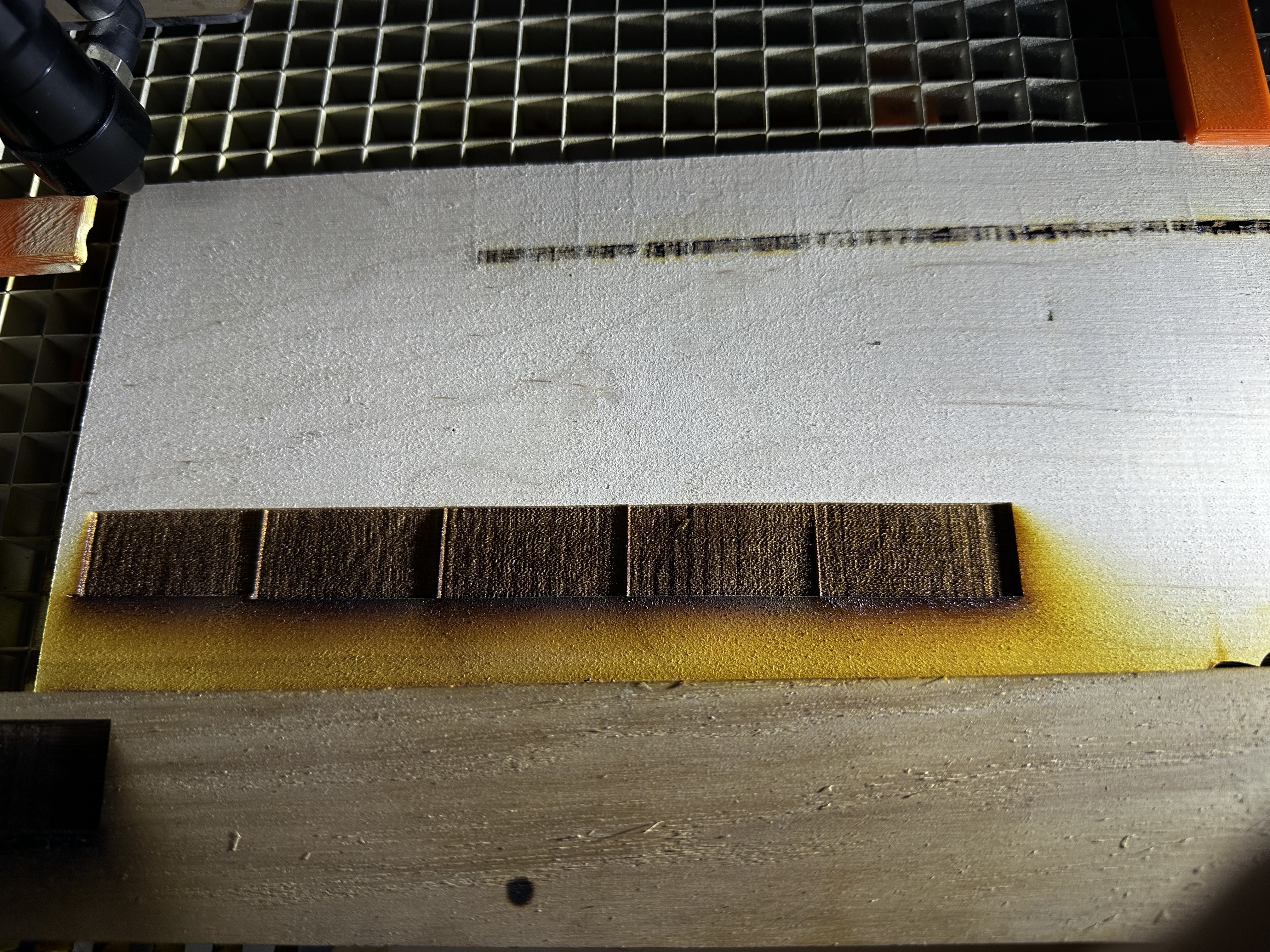
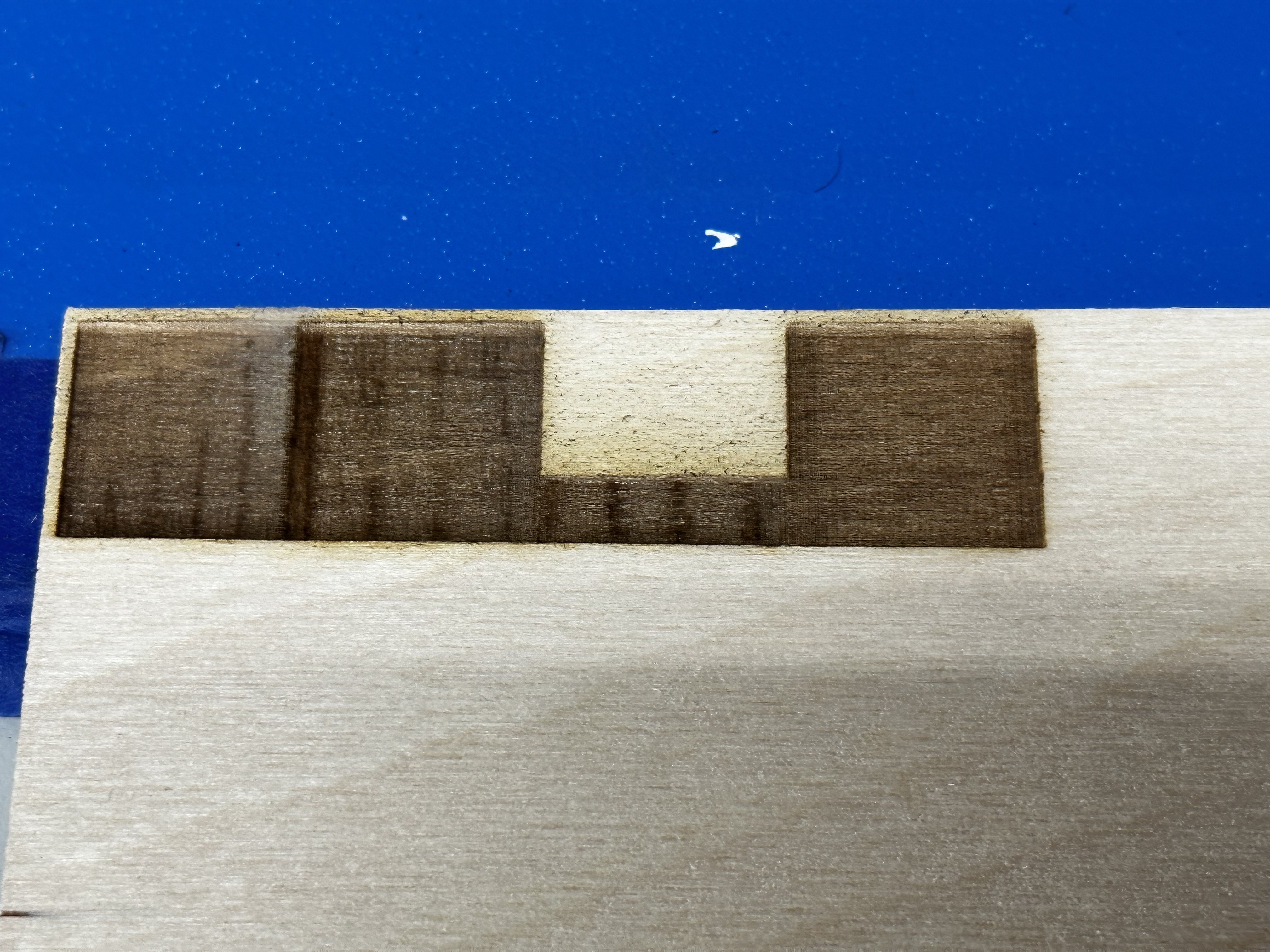
This is 250mm/s 40% power 4% over scan with stealthchop enabled on the x axis. The x axis sound completely and entirely different running in this mode.
sounds like you identified it as curtains…
![]()
I have tried upto 7800 and didn’t see any differences. Never thought to go up to 50,000. Trying now…
Here is 50,000 hz with at least two different stepper modes. I don’t think FluidNC supports spreadcycle, but it didn’t throw an error when I loaded it into the config so I ran it.
The harmonics on stealthchop and spreadcycle are so much different than coolstep its wild. Crazy what software can do.
Overall though it seems like 50,000hz is what is making the big difference. Not calling this solved until I burn at least 50 ornaments without seeing this pattern re-emerge.
Is there a guide out there for the pot tuning. I would like to have the full spread of values for power. Then my LightBurn power settings could stay the same from machine to machine (or at least closer to the same)

Edit: Not solved. Got trigger happy. Pattern is still emerging from the depths of my engravings.
1 Like
I have a couple of 3D printers made with 3D printed parts, in PLA, and one of them was a dickens and sent me threw the slicer and the controller for a couple of months. Turned out to be thermal expansion and contraction of the 3D printed parts in the carriage. On cold evenings things would get too tight and in certain spots a stepper would skip a step and then on warm days there’d be too much play/wiggle and parts wouldn’t be sized as was once calibrated. I ended up replacing the 3D printed carriages with 400mm long linear rails and things were so much better.
For a laser cutter like you have, some parts might be better off laser cut from acrylic if there’s any chance of thermal expansion and contraction causing changes in how well things track on the extrusions. ABS might not have the same properties at the temperature ranges we are talking about 60F to 90F for my setup before I upgraded to whole house forced hot air and AC.
1 Like
First off, I don’t think this is going to fix your pattern, it’s just information for once that is solved. Whether it’s mechanical or electrical, it seems that after your system rests for a while it gets better, and then after some use seems to get worse?
I know that we’ve had plenty of discussions about them here. @donkjr do you have a blog post focusing on the potentiometer?
First, though, if you haven’t read it yet, this comment might be helpful:
You might start from this comment and read forward:
@donkjr you have actual knowledge here of lots of LPSs, do you mind checking this and commenting?
I think there are two ways.
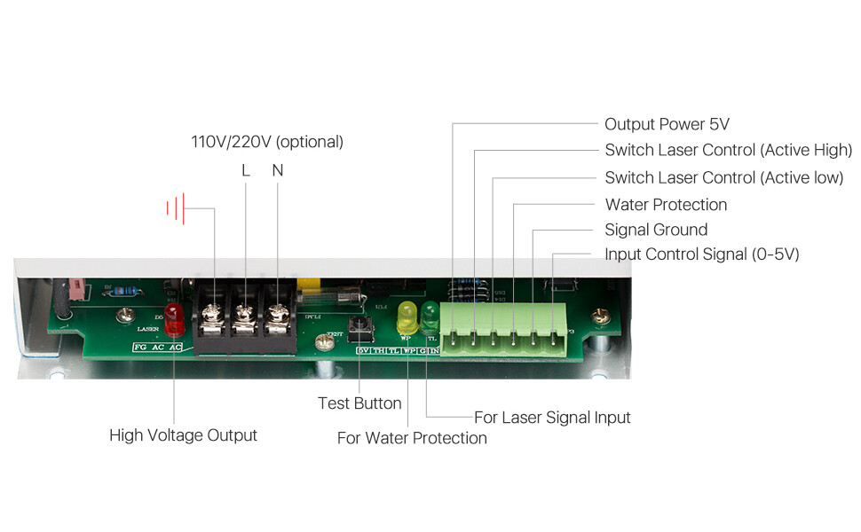
The general idea is that you hook a 1K or 10K linear potentiometer across signal ground / input control signal / output power 5V
Then I think I’ve seen two ways to connect PWM:
- connect an open drain control signal to the input control signal
- connect the PWM control signal to the appropriate switch laser control line, either high or low
I would trust @donkjr to know which is appropriate here and why. ![]()
Here’s the labelled connections for this particular LPS:
Ive built the MPCNC and its 36"x32", quite a bit larger than my big laser and the 3D printed parts are put through hell and back on that machine. Lulzbot is known for 3d printing the majority of their parts for their printers, those printers make astounding parts. I’m not saying its not the 3D printer parts, but I don’t think the forces that are being exerted on the 3D printed parts, nor the temperature changes are what is causing these patterns. My mounting plates and axes remain tight over the course of my runtimes.
That being said, I’m taking the advice I get here seriously, and don’t want to write off any observations and recommendations as not applicable.
I’m starting to think that there are certain parts of the bed/axes that are more susceptible to vibrations. That’s why when I said it works one day and not the next, it’s really because one day I was working in one area and the next day I was working in another area.
Edit: also electrical. Not sure my previous problems have been fully alleviated: CO2 Laser Interfering with stepper motors - #48 by James_Harding
1 Like
You missed my point… I was not discussing the strength of the 3D printed parts. I was talking about thermal expansion and contraction affecting mechanical parts which require stable dimensions so there is a constant force on other parts which have different thermal expansion coefficients.
I didn’t miss your point, I understand that is a concern. I think that a substantial amount of thermal expansion would have to occur, like more than 1-2 mm on the 3D printed parts.
The thermal expansion coefficient of PLA is 68µm/m-°C
The gantry that the X-Axis rides on is roughly 3" or .0762 meters
I think an absolute MAXIMUM change of 30 degrees C from when I start to when I am done. (even though the patterns show up immediately). By the way, 30 degrees C is madness.
DL = (.000068)m per m Celsius *.0762m * 30C = .000155 meters ~ .15mm
This means that over 30 degrees C the expansion of the PLA is .15mm. The deformation of the v slot wheels alone can overcome this expansion. This also isn’t taking into account the thermal expansion of those wheels. If that was taken into account, there would probably be a net change of ZERO.
Please check my math, I am not a material scientist.
2 Likes
I’d think it much more likely that you have something like an intermittently bad bearing somewhere. Works when the bad spot isn’t lined up with running into adjacent ball bearings in the race, then stutters when it moves around to run into them. Or something equally hard to find… If you are moving enough air to void the smoke, I’d seriously doubt it’s a change in temperature.
1 Like
This is killing me. Replaced the v-slot wheels, still doing it.
I’m starting to turn into a tin hat wearing conspiracy theorist. I cut out an enclosure for the controller and wrapped it in foil tape just to see if maybe there was some electrical interference happening. No change.
Disconnected the relay control for the blower, water pump and air assist to make sure it wasn’t causing interference. No change.
Changed microstepping to 64. No change.
Smacked my head against the wall. No change.
Is there a problem with the laser tube itself no being enclosed in a metal box?
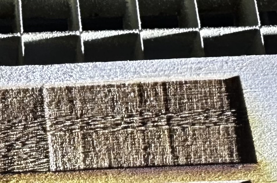
I started lightly banging the side of the laser while it was engraving and a different pattern resulted, but the underlying weird crap is still there:
Incredibly frustrating! I’ve been following this whole thing and racking my brain for helpful things to say.
I hate to come up with outlandish ideas, and I’m not sure I recommend this, but… If you put the K40 electronics and tube into the big laser, you’d know whether it’s a mechanical or electrical problem. (You would have to make something to adapt the tube size, of course.) This isn’t necessarily a better idea than smacking your head against the wall.
Higher-power tubes have a higher strike voltage. In general, lower-power tubes are better for finer engraving, and higher power better primarily for cutting. I kind of remember conversations here a few years ago about whether an LPS could/would maintain a voltage just below the strike voltage for high-power tubes to give better engraving results.
That’s ironic you mention putting the k40 tube into the big laser. I was just debating it. The major thing holding me back is the ability to fulfill orders…
I considered just buying another tube as well.
I think you can just use the existing LPS with a lower-wattage tube without problems. And there’s the point that the K40 tube won’t last forever, so a good-quality spare is more insurance for when that tube inevitably dies, right?
Sorry I was off on vacation.
This one hurts my head.
Here are my visceral thoughts as I have not read the whole thead thoroughly.
Just initial thoughts driven from experience … no facts.
Often these problems are elusive because during testing to many things are changing; speed, material response etc. This means that the underlying problem is masked by what the resulting image seems to be showing us. It’s good to simply keep trying stuff until the symptoms reveal the a-ha!
- Tempting but Not the LPS: typically these kinds of patterns are:
a. material properties [changes in how the surface burns from sample to sample and test to test]
b. mechanical tolerances [dynamic changes in motion. I have always been amazed how mechanical problems can seem to come and go]
c. combinations of a&b
I have never seen and can’t think of the mechanism for a LPS to all by itself create such a pattern especially at those low frequencies.
This will be a PIA but perhaps will provide new clues.
I would try to lock in on a very simple pattern to test with.
I like using horizontal and vertical line patterns that increase in frequency:
One dot on one dot off
Two dots on two dot off
Three dots on three dots off
etc…
Using it I would:
- Image on a very stable material like acrylic.
- Cross section and then polish the edge of the material so you can see the pattern clearly on the surface and also in penetration.
- See if that pattern and its cross section provides clues.
Then run a series of tests to isolate x and y and various speeds and powers.
I will study the above thread and see if I can be helpful.
2 Likes
And the plot thickens… I moved back to my K40 for the first time in a little over a week, and the pattern is now showing up over here. This pattern hasn’t shown up on this machine, ever. I unplugged every appliance, computer, monitor, laptop, Arduino, Pi, 3D printer, anything that was on the same breaker as the K40, and the same thing was happening.
I made a pretty bold claim a while ago over on the lightburn forums, the issue I was having with offset cuts from engravings kind of just “went away”. Now, I am really starting to think Lightburn has some config file issues or something funky going on. Maybe it is my outdated version of Lightburn, I’m not sure, but I don’t really want to pay $30 to find out.
I’ve loaded Laser Web to see if I am having the same issues with its gcode. Some strange issues are occurring. The origin in Laser Web does not match with my origin on the K40, and the work offsets that I had setup for lightburn don’t really seem to apply to Laser Web. I have gone over the Initial configuration and machine settings on the Laser Web site a few times and nothing is really jumping out at me.
The error Laser Web is throwing is this:
ALARM: 2 - G-code motion target exceeds machine travel. Machine position safely retained. Alarm may be unlocked.
I understand that this means the gcode is telling the K40 to move into a space that will crash the gantry, but when I try to do the same thing in lightburn, of course everything works nicely. Inspecting the gcode, Laser Webs gcode is working in the negative space while lightburn is not. No matter the settings in Laser Web I cannot get this error to go away. I have attached the gcode from lightburn and the gcode from LAser Web.
I have included my Laser Web configuration for my K40, maybe something can be discerned from it…
{
  "__version": "4.0.999",
  "__selectedProfile": "K40",
  "__latestRelease": "2019-11-26T10:45:07Z",
  "showMachine": true,
  "machineWidth": 321,
  "machineHeight": 192,
  "machineBeamDiameter": 0.1,
  "machineBottomLeftX": 0,
  "machineBottomLeftY": -192,
  "machineFeedRange": {
    "XY": {"min": 100, "max": 6000},
    "Z": {"min": 1, "max": 1250},
    "A": {"min": 1, "max": 50000},
    "S": {"min": 1, "max": 1050}
  },
  "machineXYProbeOffset": 0,
  "machineZEnabled": true,
  "machineZMatThickness": 0,
  "machineZToolOffset": 0,
  "machineZStartHeight": "",
  "machineZProbeOffset": 0,
  "machineAEnabled": false,
  "machineBlowerEnabled": true,
  "machineBlowerGcodeOn": "M08",
  "machineBlowerGcodeOff": "M09",
  "pxPerInch": 72,
  "forcePxPerInch": false,
  "dpiBitmap": 72,
  "toolGridWidth": 321,
  "toolGridHeight": 192,
  "toolGridMinorSpacing": 10,
  "toolGridMajorSpacing": 50,
  "toolSafetyLockDisabled": false,
  "toolCncMode": false,
  "toolImagePosition": "TL",
  "toolUseNumpad": false,
  "toolDisplayCache": false,
  "toolUseGamepad": false,
  "toolCreateEmptyOps": false,
  "toolVideoDevice": null,
  "toolVideoPerspective": {
    "enabled": false,
    "before": [
      170.66666666666666,
      384,
      682.6666666666666,
      384,
      682.6666666666666,
      96,
      170.66666666666666,
      96
    ],
    "after": [
      170.66666666666666,
      384,
      682.6666666666666,
      384,
      682.6666666666666,
      96,
      170.66666666666666,
      96
    ]
  },
  "toolVideoLens": {"a": 1, "b": 1, "F": 1, "scale": 1},
  "toolVideoFov": {"x": 1, "y": 1},
  "toolVideoResolution": null,
  "toolVideoOMR": false,
  "toolVideoOMROffsetX": 0,
  "toolVideoOMROffsetY": 0,
  "toolVideoOMRMarkerSize": 20,
  "toolWebcamUrl": "",
  "toolFeedUnits": "mm/s",
  "toolTestSValue": 1,
  "toolTestDuration": 0,
  "gcodeStart": "G00 G17 G40 G21 G54\nG91\nM4",
  "gcodeEnd": "G0 X0Y0\nM2",
  "gcodeHoming": "$H",
  "gcodeGenerator": "default",
  "gcodeToolOn": "",
  "gcodeToolOff": "",
  "gcodeLaserIntensity": "S",
  "gcodeLaserIntensitySeparateLine": false,
  "gcodeSMinValue": 0,
  "gcodeSMaxValue": 1050,
  "gcodeCheckSizePower": 1,
  "gcodeToolTestPower": 10,
  "gcodeToolTestDuration": 200,
  "gcodeConcurrency": 2,
  "gcodeCurvePrecision": 0.1,
  "comServerVersion": "4.0.138",
  "comServerIP": "localhost:8000",
  "comServerConnect": false,
  "comInterfaces": ["USB", "ESP8266", "Telnet"],
  "comPorts": [
    {
      "comName": "COM4",
      "manufacturer": "Arduino Srl (www.arduino.org)",
      "serialNumber": "55431303937351908102",
      "pnpId": "USB\\VID_2A03&PID_0043\\55431303937351908102",
      "locationId": "Port_#0002.Hub_#0002",
      "vendorId": "2A03",
      "productId": "0043"
    }
  ],
  "comAccumulatedJobTime": 3463,
  "connectVia": "USB",
  "connectPort": "COM4",
  "connectBaud": "115200",
  "connectIP": "",
  "jogStepsize": 10,
  "jogFeedXY": 1000,
  "jogFeedZ": 100,
  "macros": {
    "*GotoXY0": {
      "label": "Goto XY zero",
      "gcode": "G0 X0Y0",
      "keybinding": "f1"
    },
    "*LaserOff": {"label": "LASER OFF", "gcode": "M5", "keybinding": "f2"}
  },
  "uiFcDrag": null,
  "machineOriginX": 0,
  "machineOriginY": 0,
  "toolUseVideo": false
}
Lightburn GCODE:
; LightBurn 0.9.14
; GRBL device profile, current position
; Bounds: X0 Y0 to X40 Y20
G00 G17 G40 G21 G54
G91
M4
; Cut @ 6 mm/sec, 35% power
M8
G0X0Y0
G0Z-2
G1Y20S367.5F360
G1X40
G1Y-20
G1X-40
G0Z2
M9
G1S0
M5
; return to starting pos
G0 X0Y0
M2
Laser Web GCDOE:
G21
G90


;
; Operation:    1
; Type:         Laser Cut
; Paths:        1
; Passes:       1
; Cut rate:     100 mm/s
;


; Pass 0

 M08; Enable Air assist

; Pass 0 Path 0
G0 X41.00 Y-21.00
; Pass Z Height 0mm (Offset: 0mm)
G0 Z0.00

G1 X1.00 Y-21.00 S367.50 F6000
G1 X1.00 Y-41.00
G1 X41.00 Y-41.00
G1 X41.00 Y-21.00
G1 X41.00 Y-21.00

 M09; Disable Air assist
M2
G0Z50
G0X0Y300
M911G4P500M912G4P100M911G4P100M912G4P50M911G4P100M912
@mcdanlj
There is no such setting, it only depends where the work origin is set. But we always expect to have positive directions to the right / back.
@James_Harding
There is a difference between machine coordinates and work coordinates. Homing sets the machine origin (0/0). LaserWeb internally uses work coordinates (with positive directions to right/back), so the origin can be set where ever you want. You only need to make sure that the firmware reports work coordinates, not machine coordiantes (GRBL $10=0).
If LW reports that a move will go out of bounds, this is related to the work origin. Move to front left and click “set zero”. This will set the work origin to the actual location.
In GRBL you can configure the homing coordinates that are set at homing. For example: If you home to back left, then homing coordinats could be set to 0,192 (which sets the machine origin to front left).
1 Like
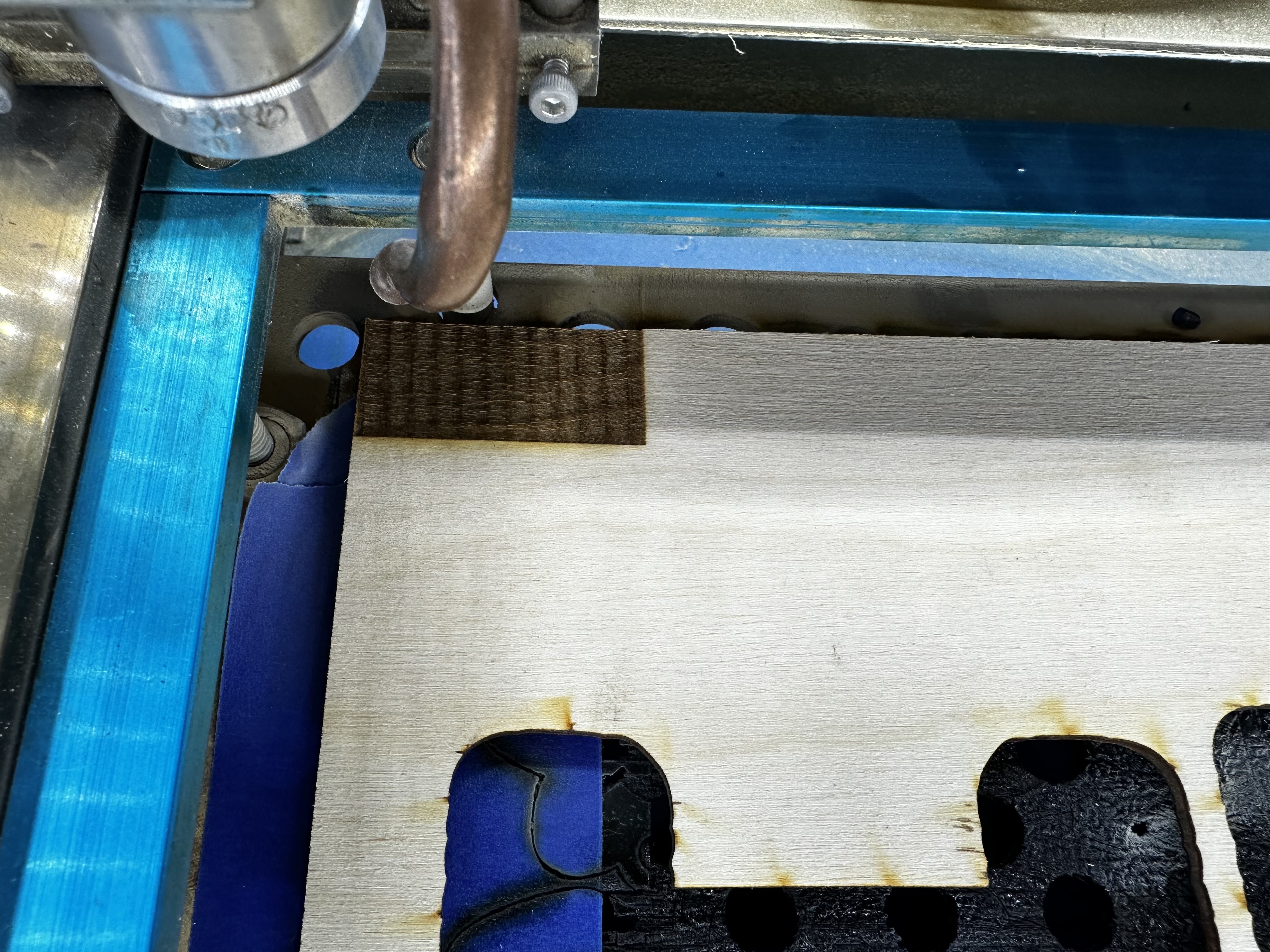
Progress report…
On the K40, it seems I was able to shake the issue by adjusting the $30 Max Spindle Speed. I’m not sure how or why this changed, or why I needed to change it but the image below is pretty telling.
I think that this might actually be the issue. I have ordered a set of pots for the big laser, I plan on doing the installation tonight, although I’m not 100% on how to tune the software, searching the google machine now for some guides.
Edit: Upon further review of the FluidNC wiki, I don’t think I need a potentiometer in the loop. The speed_map they provide should allow me to limit the max output of the laser, while giving full resolution of power at the same time: Spindle Speed Maps | Wiki.js
The speed map (which you are already using) doesn’t magically preserve resolution.
The output PWM values are still a linear series, and if you map to a different range you use only the values in that range.
I’m not saying you need a potentiometer, but the speed map won’t give you full resolution. I don’t know if it will matter, though! If it would I would have expected to have had a change (if not an improvement) from changing pwm_hz.