I measured the BSC head and the diameter came out to be 9.3mm. The leveling block recessed hole is about 8.48mm. I suspected that the blocks I have may have been different from the model. It’s all good though and I’m fine with using the printed ones I have. Thank you for the offer Eric!
I do have question about the side carriages and the cross rods. Are the cross rods supposed to be easily pushed into the side carriages? I started to assemble the gantry and because of how tight the rods fit into the side carriages it is really difficult to adjust.
It is a tight fit by design. But if it’s too difficult to fit in, it could be chased with a 8mm drill bit.
I did chase them with a 5/16 bit I think which is 7.9375mm. I didn’t want them to be too loose, but if that 0.0625mm press fit is causing issues and you don’t have an 8mm bit, you could just take the 5/16" and give it a little bit of a wiggle to open it up.
Okay I’ll give that a try if I can’t get it adjusted perfectly. I haven’t been able to get the sweet spot once I connected the cross rods to the side carriages. The side carriages moved great on their own though.
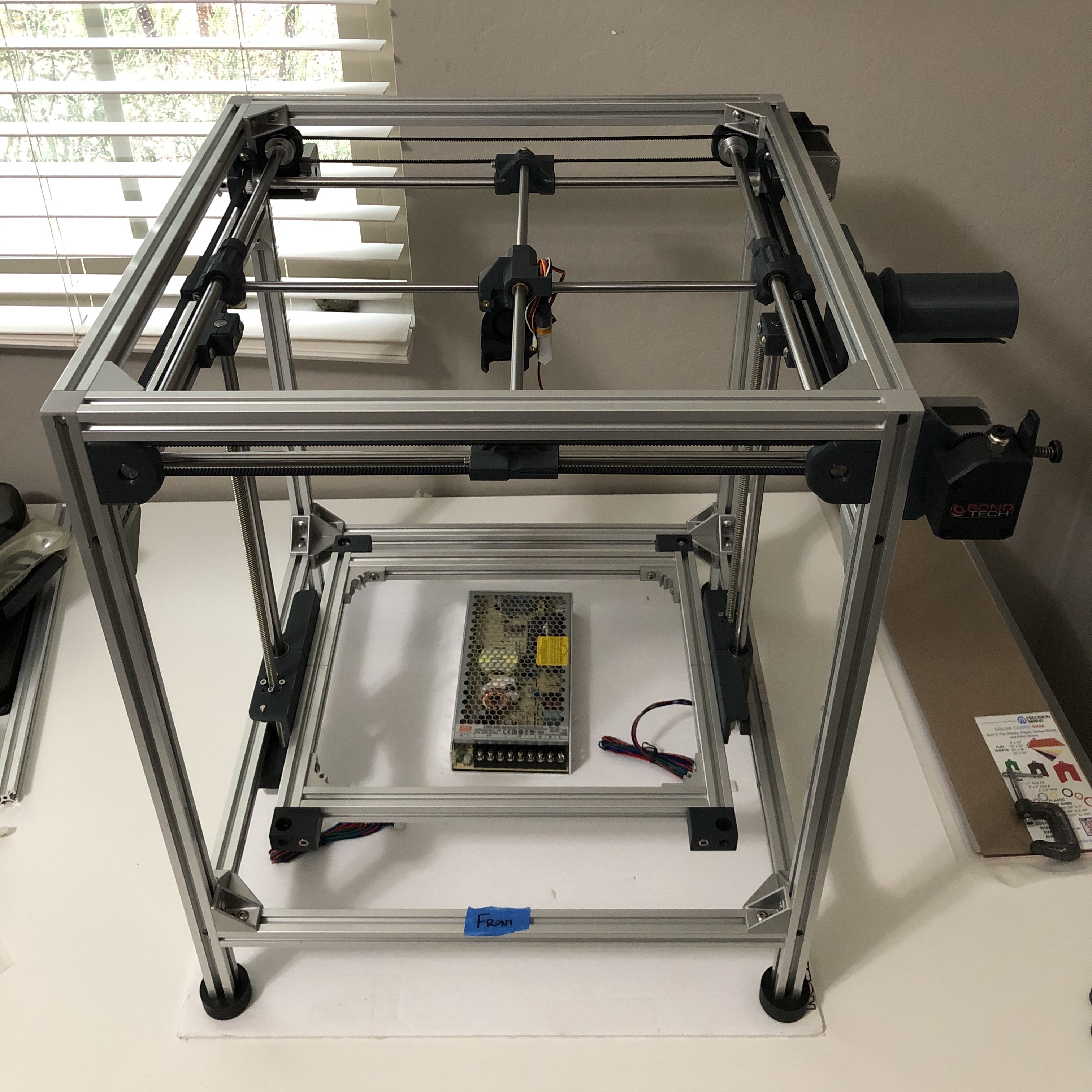
I made some progress over the long weekend on my build. I got the bolts I needed to install the corner leveling blocks and have the frame installed onto the printer. Gantry is also installed with belts following Eric’s video for alignment. I can move all around with a finger. It’s not as smooth as when the parts were on their own but I imagine the break in will get it smoothed out. I’m still waiting on my controller so hopefully it arrives soon so I can run the break in and test my hotend. In the meantime, I need to get the bed plate drilled and countersunk for the mounting bolts and thermistor as well as a new thermistor to mount to the bed.
It’s looking really great, I am excited to see you when you get to put the first moves on it. The break-in G code from the Eustathios 2 repository should help things smooth out a bit. It’s a lot of stacked up tolerances that have to kind of equalize themselves out.
You probably noticed that it was pretty stiff without the belts on, but as soon as you install the belts and get everything squared up the gantry moves better. That’s because any amount of racking tends to side load the bushings causing them to stick a little bit. Luckily the bronze bushings do kind of wear in a little bit which will make the motion much smoother.
Thanks Eric. That was exactly my experience prior to putting the belts on. I tried hard to get things aligned as much as possible so that it was smooth off the bat but I couldn’t quite get it as smooth as when things where not all connected. Anyway, I still feel pretty about it and hoping the controller gets here soon.
Hey all. Not much progress since I’m still waiting on my controller and screen. I’ve been going back and forth with Biqu on my order from them for the past two weeks trying to locate my order. According to tracking records, its been in Compton, CA since July 24th. Anyway Biqu sent me this the a few days ago:
Thank you for your understanding. The logistics provider said will reply within 1 week to 1 month. If the item is lost or cannot be delivered to your address, I will arrange for you to resend it as soon as possible
I know that COVID will impact deliveries but I’ve gotten everything else from China within a matter of a couple of weeks so I’m at a loss on what’s going on with my order from Biqu. Anyway, that is not really what I wanted to focus on for this post. I figure I take the time to start mapping out my wire runs since my electronics placement will differ from the design since I won’t have a bottom panel. It’s clear that the wires I received with my parts for the X stepper, Y stepper, Extruder stepper, hotend, and heated bed will be not be long enough and will either need to be extended and or a new harness made to length.
I am trying to decide which is better to put my money and effort into. The cables are all different sizes and if extending the wires, I would have to get all the different gauges to match what came and splice them. And since they all have different connectors to the boards I may have to replace those too.
OR
I make new harnesses and consolidate cables to 2 or 3 different gauges . From reviewing other posts about wiring and determine the amount of amps that will be running through the cables, I am thinking 14 awg for PSU to board, SSR, and heatbed, 18 awg for hotend heater cartridge, and 24 awg for everything else (steppers, fans, etc…) should work.
So a few questions:
What have others done and their experience with their choices? What worked and what didn’t? Anything you would have done differently?
For anyone running the BTT SKR 1.4 board are all the connectors JST-XH type connectors?
For terminating the Molex Micro Fit connectors, what crimpers have worked well for you? I’ve seen a lot of positive things about the Molex 63811-1000 and the Engineering PA-09.
I’m making of list of things I’ll need to order so your input is greatly appreciated!
Sorry, I should have just put amazon links in the BOM vs BTT directly. Sorry they have treated you so poorly.
For crimpers, I own many. But these ended up being my favorite. You have to crimp the wire, then the insulation separately with these. But I get way better crimps, and I can afford the extra time.
For cables I make all my wiring from scratch. I get good quality belden or carol multiconductor wires and make each to length. Either that or I get good quality silicone wire and makeup individual harnesses and put nylon braided sleeve over the top.
But I have the benefit of working at a place where I can get end cuts from some of our work automation projects so it basically doesn’t cost me anything. When I first started I did a lot of premade wire lengthening. That’ll work fine too, but I don’t necessarily like having all those splices everywhere. I’m kind of a wiring fanatic at this point.
@Eclsnowman Those look conceptually similar to the PA-09 to me, but cheaper, available with quick shipping (vs. the two month slow boat from Japan for my PA-09s), and two extra sizes of crimps as well.
I have an IWISS ratchet crimper which crimps both wire and insulation, and at first didn’t like the PA-09, but now I pretty much only use the PA-09 and wouldn’t want to go back to the ratchet crimper. If I had known about that AWG28-20 I would have bought it instead.
Hey Eric it’s not your fault what Biqu is doing so no worries. It was much cheaper going directly to them vs Amazon so I took a chance that it would arrive when they estimated it would. I just wanted to share my experience in case anyone else was considering ordering through them.
Anyway, thank you for the response. I like a clean wire layout and install so I think I’ll be making my own harnesses and keep the splices you a minimum. I’ll also check out the crimper you linked to.
That’s the same experience I had with the ratchet crimpers… of which I own two. It’s faster in theory, but I found the time it takes to shorten wires if I have to cut off a 'miss crimp" is not worth the speed the ratchet crimpers provide. Plus since I’m only crimping one of the two tabs at a time I can get far more precise crimps especially if the crimper isn’t an exact fit for the wire end im using. Plus I found I can fit slightly oversized wires into a terminal end if needed because I have a lot more finesse with it. Overall that crimper I linked has become a favorite tool in my maker toolbox.
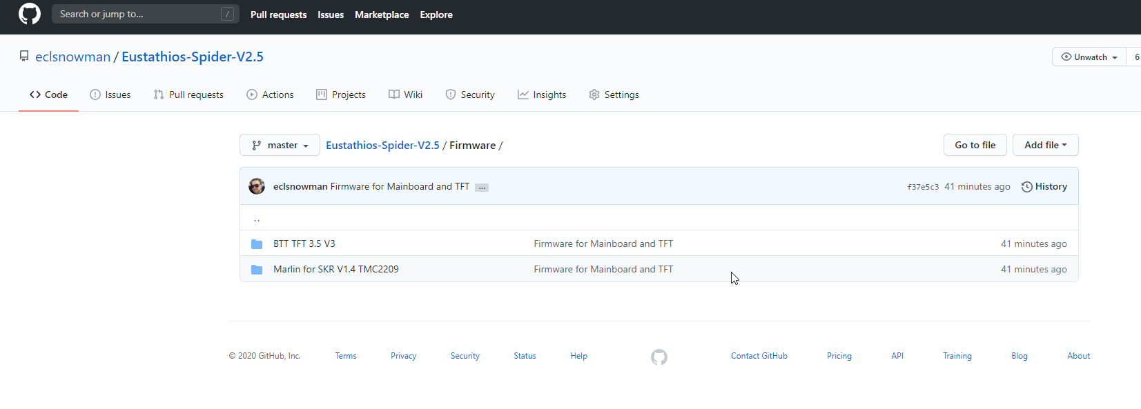
FYI, I just did an upgrade of my Eustathios V1.65 to the latest Marlin 2.0.7 and switched from my 4x LV8729 drivers to 5x TMC2209 drivers per my current Eustathios BOM. So I took that config, adjusted it for the Eustathios 2.5 and uploaded the marlin firmware.bin, the marlin VSCode folder, and the BBT TFT35 custom setup I use to the Github for the Eustathios V2.5. It should give you a good starting point for your firmware once your board arrives. I have a few things that differ since I have an older printer design, so please take time to double check my work getting it configured for the V2.5. But I hope you can find it helpful. If you find any required changes please let me know.
One thing to note is with my latest upgrade I implimented dual independent Z via 2x drivers so that the bed can auto-tram with a G34. This is implemented in the firmware I just uploaded. So if you plan to use it make sure to use independent drivers for each Z motor.
Another thing to note is that even though the BTT touch screen is very handy… I also have a lot of niece features implemented from the standard Marlin Full Graphics Smart Display menu system which are not in the BTT Touchscreen menu yet. So when you are configuring perhaps look into starting the TFT in Marlin mode while you dial in the printer. Once everything is configured the TFT touchscreen is easier for day to day use. But the Marlin Mode has more horsepower
Hi. I’m hoping to get some help with wires and had a couple of questions. But first a quick update on my build. I got my new BIQU SKR 1.4 turbo board and TFT board and started to layout where the electronics package will go. Since I’m not running a base cover I’ve been investigating options and examples from other builds. I’ve decided to mount the PSU, SSR, and controller board to a DIN rail that I’ll mount to the bottom of the printer.
I also started planning out the wiring. Due to the size of the printer and how I plan to run the cables, the stock cables that came with most of the electronics and hardware will be short. I want to avoid splicing cables and made custom length cables for the X, Y, and extruder. It was my first stab at crimping such small connectors but got them down after a few tried. I’m hoping by next weekend I will have all but the hotend and heatbed wired up and can start getting the SKR board configured for it’s first movements!
Okay, so the problem I am running into now is that I’ll also need a longer hotend heater cartridge extension wire and heatbed wire. The E3D V6 hotend wire looks like some kind of high temp fiberglass woven covered wire. I can’t seem to source it or figure out what kind of wire it is so I can get the length I need. Would anyone know what kind of wire it is? I have some 18 awg silicon cable on hand that is high temperature resistance 200 degree C. Would that be a safe alternative to use?
Normally I make sure to have some sort of electrical union connection out on the hot end to make things easy to replace (jst, microfit molex, etc). So I just run normal my silicone wires out to the hot end carriage inside a woven nylon sleeve, and then have my connection out there which meets up with the heater cartridges and thermistors wires.
Thanks Eric. I plan to use the same connectors that came with the V6 hotend which appears to be Molex Microfits. The extension cable that it came with was just a bit short so I’m making a new one. Do you have just the heater cartridge cable in the nylon sleeve by itself or can it be bundled with other cables?
Also, do you know the wire type the OE E3D V6 heater cartridge came with?