That looks right to me, and I think it’s what @cprezzi suggested. (He gets the credit…  )
)
1 Like
Excellent! I’ve got an old extension cord that I can use to wire this up for a test. I want to be sure it works as expected before using the circuits in the K40.
1 Like
@mcdanlj Thanks for the credit, but it’s a team effort, like mostly everything on this forum!

5 Likes
Yes, thanks to @mcdanlj and @cprezzi for all the help. I wired it up with jumper cables today and everything worked as expected (e.g. LED on and 120 VAC at the outlet end), but only for a few seconds. The resistor started to smoke so I had to unplug everything. I got another resistor for a second try with the same result. I’m pretty certain I’m using a 1K ohm resistor. It looks like this:
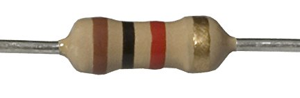
Not sure what to do now. Thoughts???
That’s 1k, yes. I didn’t think hard about resistor value. Since we don’t really know precisely what’s in there, I’d try much higher values. If it were me, I’d try something like 100k and see if it illuminates. I’m wondering if it’s not really an LED — if it’s a small indicator bulb it will act very different. Do you have an ammeter available?
The listing on Amazon (link earlier in this thread) indicates it’s an LED. I’ll try stronger resistors. Yes, I have an ammeter like the one I’ve installed in my K40 and my multimeter can measure up to 10 A.
Ok, typical LED current is 10-20 mA. If it’s much more than 20mA it’s going to burn out the LED and you need more resistance.
But… We should have done a few more calculations. Power calculations are based on RMS voltage not peak voltage. The LED drops a few volts, but its entire voltage drop is within the normal range of variation and is insignificant compared to the total, so the resistor drops about 120V. And then we divide by 2 because it is half-rectified. 120V * .02A / 2 = 1.2W
A typical 1/4 watt resistor can’t dissipate 1.2W indefinitely without catching fire…
I’m very sorry, I should have done this calculation earlier.
There are at least four possibilities that come to my mind:
- Use a power resistor that will get hot (ugh, I wouldn’t do that)
- Use the voltage to control a switch (e.g. a MOSFET on -) and use DC voltage from the power supply for the LED (requires building a circuit with several parts)
- Use a switching power supply for the LED. This is easy if you have old “wall warts” that you can power from the switched side (in parallel with the switched outlet) and use to drive the LEDs. If the product listing is to be believed, you can use a wall wart up to 12V without a resistor.
- Give up again on the round switches and use the square version you found after all, which has something integrated into the switch to Just Work when switching 120V. I would test that one works before modifying the panel, though…
On reflection, I would think that you could just use a small file to open out the round holes for the first switch you found to use the square integrated switches, instead of making a large patch or using a nibbler as I initially suggested. Do you have pictures of the panel you have milled? Or, if the square switches are smaller than the round switches, you could 3d-print a round plug with a square hole in the middle. Either way I’d expect a small modification to be sufficient.
1 Like
OK…I’ve tested three other resistors with the following results:
4.7K - LED illuminated, but resistor got pretty hot after about a minute with a distinct odor
10K - LED illuminated, but resistor got hot, but very little odor
11M - LED did not illuminate
I think I’m very close to getting this circuit to work, I just need to test some resistors in the 15K to 100K range. However, I just re-read your post and now I’m wondering…when you wrote “A typical 1/4 watt resistor can’t dissipate 1.2W indefinitely without catching fire”, does that mean there’s NO resistor that will work in this situation? Would a 12K, 2-watt resistor work? It seems to fit in the resistance range and the wattage rating satisfies the over-heating concern you outlined above.
The power rating (e.g. 1/4 watt) is for maximum continuous safe power in free air.
I expect a 12K, 2 watt power resistor would work. It will produce almost as much heat as the 10K resistor. You might be able to screw it to the metal case to use the case as a heat sink, so that it is at a lower temperature because the heat will dissipate more readily.
I would use the highest resistance that gives you sufficient illumination; it will dissipate the least heat, and preserve the LED because heat kills LEDs.
The higher the resistance of the resistor, the lower the current through the LED, which also means the lower the current through the resistor (see Kirchhoff’s law) which means lower power consumption in the resistor.
1 Like
OK…thanks for the tips. For the heat, maybe I’ll add another fan for the underside of the control panel.
I was thinking of the metal case resistors for screwing to the case, but those are typically larger than 2W, so ignore the part about screwing them to the case. I don’t think you need an extra fan.
I found a 27K, 5W resistor locally and tested it. I left the circuit on for a few minutes and the resistor got warm, but I could hold it between two fingers immediately after turning the circuit off. I think it will work! Actually, I think I could go even higher with the resistance since I’m not seeing any reduction in the brightness of the LED. OK…I’ll not worry about the heat.
1 Like
Going back to the ammeter like the one you installed in the K40: If you put it in series between the LED and the resistor, it will display the average current, so you can multiply directly to get the power. If, for example, it displays 5mA, then you can 120V * 0.005A = 0.6W — don’t divide by 2, because (basically) the inertia of the indicator is doing that for you already.
You might be able to avoid buying a power resistor in this way. If you determine, for example, that a 40K resistance gives you sufficient illumination and 5mA current, you could connect 4 10K resistors in series. Each one would drop about 30V, and 30V * 0.005A = 0.15W so you could use four 1/4W resistors and each one would do 1/4 the total work of dropping the voltage, and 0.15 is substantially less than the max rating of 0.25 so it would be a safe use of those resistors.
1 Like
I appreciate all the thought you’ve put into this and I’ve gotten the circuit to run using my extension cord testing system. However, when I tried to actually install the circuit into the K40, I had serious issues. The main power inlet on the K40 isn’t the same as a 3-prong plug like the extension cord. Since it’s on the main power switch on the K40 control panel, I’ve learned I can’t simply tap into it to supply power to my new switches. At least, not the way I had it wired. At first my only issue was that the circuit didn’t work in the K40 like it did on my workbench (e.g. it was always on). Once I realized that the main power inlet was a switched outlet, I tried to power the new switches with power coming from the K40’s power supply, When I used positions 3 (neutral) and 4 (live, hot) on the power supply to supply power to the new switches, I tripped a breaker that, evidently, also powers my main modem for my home’s Internet. That was a hassle! Unless, there’s an obvious and easy-to-fix solution to this situation, I think I’d better stay with the original wiring of the K40 and be content with having the air assist, water cooler and exhaust all coming on when I fire up the K40.
It’s up to you. This can be solved too. But take some pictures and post them if you would like to solve this. Most likely you inadvertently shorted the connection… If you do that, show what connections you did make, precisely.
But it’s not an obligation.
Man…I thought I was done with this, but your offer (along with my stubborness) has prompted me to keep going. I’ll take some photos and label them the best I can. It’s pretty much a rats nest at first glance.
OK…here are some photos. I hope they’re good enough to make some sense of all this.
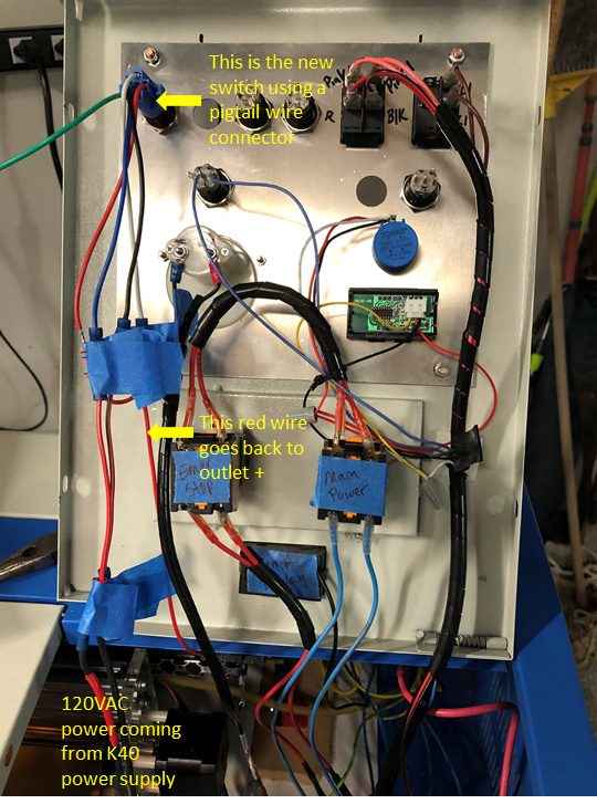
The pigtail wire colors are as follows:
Red: pin +
Black: pin -
White: C
Blue: NO
Green: NC (not used)
All the painters tape is temporary protection for shorts.
All the hots are tied together, all the neutrals are tied together and all the grounds are tied together. When the new pushbutton switches are installed, the hots will be separated and connected to individual switches.
I realize now that I need to separate the power to the outlets from the main power inlet. I thought I could get that power from the K40 power supply.
There is 120 VAC on the outlet side of the “Emergency Stop” switch. This is convenient since the Emergency Stop is located on the Control Panel near the new pushbutton switches. The wires currently coming from the Emergency Stop go to the Load and Neutral positions on the power supply (#4 and #3, respectively). I found that Load and Neutral are reversed on my power supply. I probably need to reverse those???
The wiring would look like this:
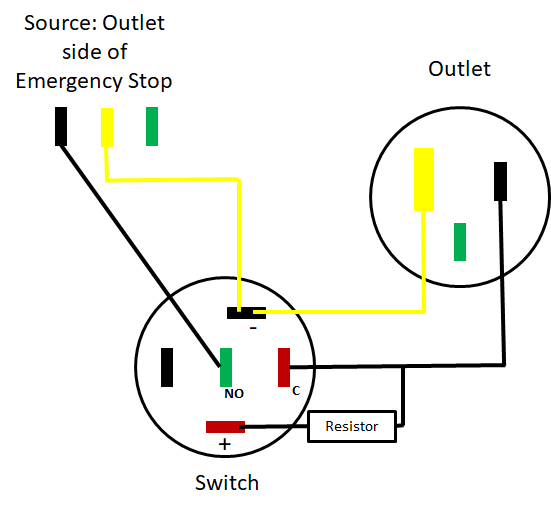
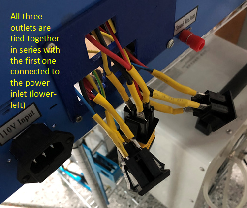
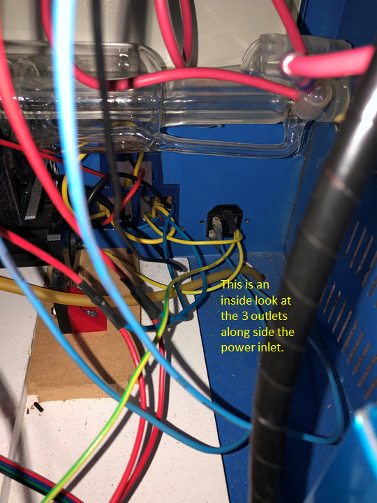
I still need to separate the 3 outlets from the main power input on the back of the K40. If this is OK, I just need to figure out how to handle the ground. Thoughts? Suggestions?
Oh, I’m so sorry that I also forgot to calculate the power dissipation. In this case I would also suggest to use a 120VAC to 12VDC converter like this one (instead of the resistor):
Just connect the inputs in parallel to the (switched) outlet and the outputs to the LED pins.
You can leave the neutral and earth pins of the outlets connected directly to the source outlet, just the L pins needs to be separted and routed via the new switches.
For the power supply it doesn’t realy matter if L and N are swapped, but for a clean wiring I would change them to the correct way.