I’m replacing my digital control panel to include an ammeter and analog power controller. I’ve got that all working and now want to add some LED pushbutton switches on the panel to control power to the back outlets. I’ve replaced the original two outlets with 3, US-style grounded outlets. What I plan to do is use LED pushbutton switches to turn the air-assist pump, water cooler and exhaust fan on and off. I’ve got the pushbuttons mounted and can get them to work as buttons, but I’ve not figured out how to get the LED to light up with the power is on and off with the power is off. The button came with schematic diagrams, but I don’t understand it and I’m concerned about “mixing” the 5VDC for the LED with 120VAC for the outlets. The pushbutton switch is rated for 5A/250VAC and 5A/30VDC. Can anyone help me figure out how to connect the AC outlets and the DC power for the LED so I don’t fry this switch? Thanks!
You haven’t shared any information about the switched you are using, which makes it hard for anyone to help. Please provide a link to the actual product you purchased, and images of the schematic that came with the button, to start.
OK…here’s a link to the LED push button switch I plan to use:
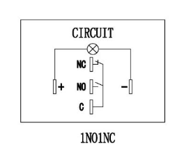
And a photo of the instruction sheet that comes with the switch.
When I contacted the manufacturer on Amazon, they replied as follows:
Pin C and pin NO connect to your outlet circuit.
pin + and pin - connect to the 5VDC circuit.
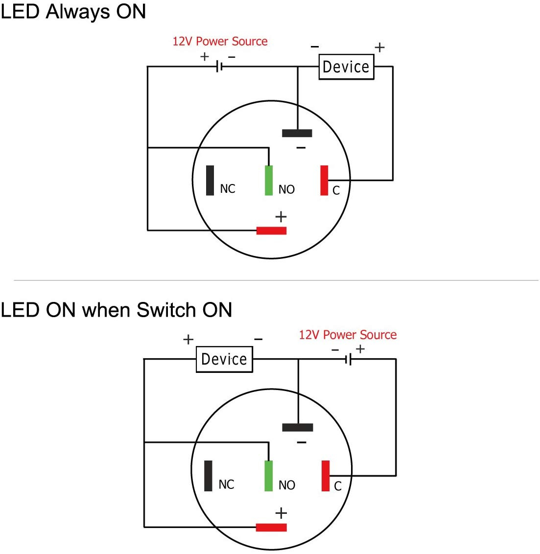
This works to control the outlet, but the LED is on all the time, and I want to have the LED on only when the device I’m controlling at the outlet (e.g. air assist pump, exhaust fan, water cooler) is powered on.
So you would be using C and NO pins for controlling the AC power. Then to power the LED separately you would need to supply 5V DC to the + & - pins. You could possibly pull 5V from the laser power supply but the stock supplies are notoriously under powered. I can’t imagine the LED pulling much current so it “might” be ok. Still would recommend wiring in a separate 5V converter to power the LED and other possible upgrades needing 5V power. Would you concur @donkjr?
From the amazon page.
Thanks for the reply, but this is the recommendation from the manufacturer and it does work to control and the AC, but the LED is on all the time. The reason I got these particular LED button switches was so the LED is only on when the AC power circuit is complete. When not, I want the LED off. Thoughts?
As far as I can tell, those diagrams are for using the same DC voltage for the LED and and device powered, as you might in a car. Best I can come up with is to light the LED by rectifying the switched AC. There are cheap low current switching power supplies that you could use. Cheaper and easier than transformer, rectifier, capacitor, and resistor to build your own.
Sorry your right, miss read your post. I agree with @mcdanlj, I don’t think there is straightforward way to do what you want with the switch without extra components.
Another way maybe to use the switch to control a relay to switch the AC. That way the switch only sees DC voltage, which is what is appears it was really designed for.
I’ve been waiting for the manufacturer to reply, but, so far, no help. I think you’re right, though, about the need to use the same voltage.
Yeah, I’m thinking I had better go with illuminated, 4-pole rocker switches for this application. Something like these:
That looks more likely to work well. Sadly you can’t just drill a round hole, so you’ll need a nibbler if you don’t already have a square hole to install it.
You can just put it in between hot supply and outlet for the switched socket in position 1, and ignore position 2 that is for DC, and it looks like it will do what you want. 
Thanks for the confirmation! Yeah, I already have the holes milled in the Al panel, so I’ll have to cut those out with a larger rectangle and 3D print a “patch” to house the 3 new rectangular switches. I’ll use blue filament to match the K40 case. Maybe it won’t look too bad. As long as it does the job, I’ll be happy.
Your original switch is rated for 5A 250VAC and the LED is 15mA 12V AC or DC.
Because a LED is a half wave rectifier, you can just add a resistor in front of the LED to reduce the voltage.
I’m just a bit concerned that you wrote it’s already working with the LED permanently on! Without any additional power supply or components? This would mean you have connected the LED to 120VAC, which should destroy the LED (or it is not the specified switch).
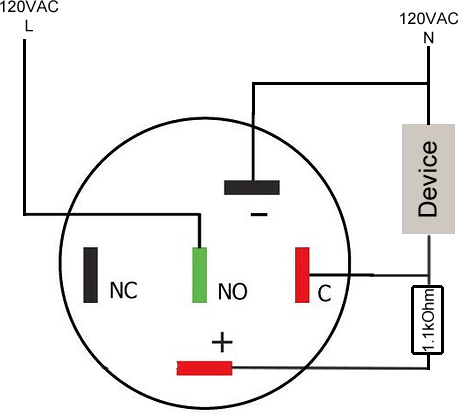
If the switch is as specified and you like to switch 120VAC (which is ~ 170 V peak), you need a resistor of about 1053 Ohm in front of the LED. So use a 1.1kOhm resistor.
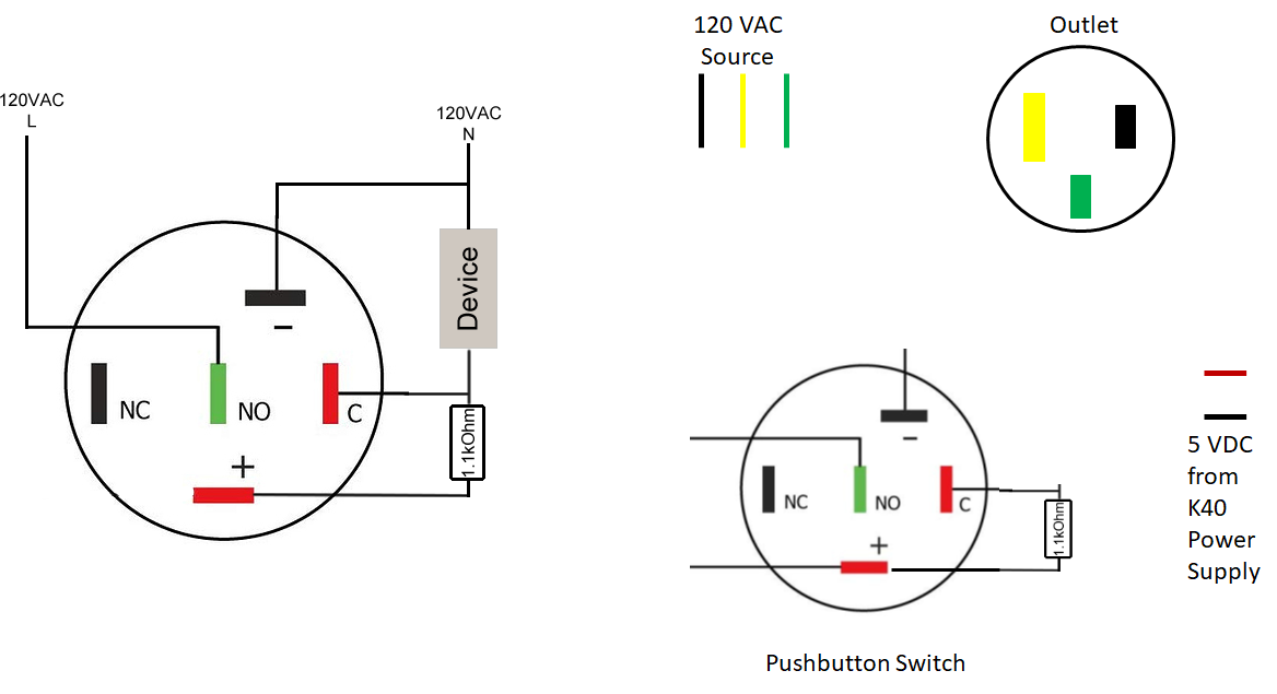
Here is the diagram:
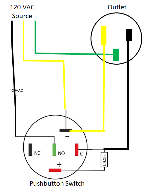
Thanks for the thoughtful and helpful reply! I get the need for a 1.1kOhm resistor, but not sure about what’s meant by “Device”. I’ve created a new graphic below showing your drawing on the left and a cartoon-like drawing of what I’m trying to create on the right. I made the neutral line yellow since white didn’t show up on the screen. Maybe you could detail the wiring connections between these components so I can be sure to get it correct??? Thanks!
PS Yes, I plan to power the LED with 5VDC from the K40 power supply.
First, make sure your switch is rated for the AC you’ll be switching. That looks OK here, with the switch at 5A, 250Vac. But you always want to be sure. Automotive switches rated for less than line voltage might support a sustained arc for higher voltages.
If the LED terminals are separate from the switched terminals, you have free rein to make it whatever you like. Making the LED run from the K40 5Vdc will serve as a diagnostic that the power supply is actually running. It’s possible to make an LED work from mains voltage. For this you need at least the LED, a resistor to limit current, and another diode to protect the LED from power line reversals.
A slicker way to do this is to use a capacitor in series with the AC mains to drop some of the excess voltage capacitively, a resistor to limit the LED current, and the same LED plus diode to protect the LED. The added diode can be either in series with the LED or in anti-parallel.
Running it from the AC mains would let you know that the switch was turned on, not that the K40 power supply was running. This is a different bit of info, but might be more useful.
If you want the light to be off while the switch is off, I think you need to power it from the AC line the way @cprezzi suggested, or go with the square switch.
I think there’s an internal resistor for the LED but that it is sized for 12V, so a 1K or 1.1K resistor that @cprezzi suggested is exactly right.
Where it says “device” that’s the outlet. Hook up ground directly to ground, neutral directly to neutral, but hot to NO and the switched outlet hot to C.
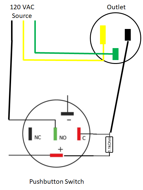
Almost like that — I was trying to explain @cprezzi’s diagram. You still need to connect - to neutral as well in order for the LED to illuminate.
Basically, inside the switch, there are two completely separate circuits. One is a single pole dual throw switch (that’s the NC, NO, and C terminals) and the other is a completely separate LED (that’s the + and - terminals).
When you put sufficient voltage across +/- you illuminate the LED. If you put too high a voltage, the LED draws too much current, and you burn out the LED. (Incidently, if you want to make the LED a bit more dim, you can reduce the current by using a higher resistance; say, 2K; this will also prolong its life.)
Each time you press the switch, you alternate between connecting C to NC, and C to NO.
Do I correctly understand that you want to know that the outlet is energized, not that the K40 power supply is energized? If so, and your goal is that when C is connected to NO, then you both connect the hot 120VAC source to the switched outlet and illuminate the LED. To do that, you connect the switched side of the hot line to the LED through a large enough resistor to protect the LED from burning out, as well as to the hot side of the outlet.
I don’t think you need a separate diode to protect the LED. It’s common to have LED light strings with only inline resistors and using the LEDs as the only rectifying components; I have LED rope light of that sort. You just have to account for the peak voltage (170V peak for 120V nominal RMS because you multiply the nominal voltage by √2 to find the peak voltage, which was how @cprezzi calculated a good suggested resistor value) when sizing your resistor.
I believe that you shouldn’t need filtering unless you are sensitive to 2x mains frequency (120Hz in the US) flicker.
Hope that helps! Thanks again to @cprezzi for pointing out the easy solution here.