Wiring for this: I have a manual enable switch on the Laser Power Supply.
Wiring for Arduino ground
Connector side of the LPS
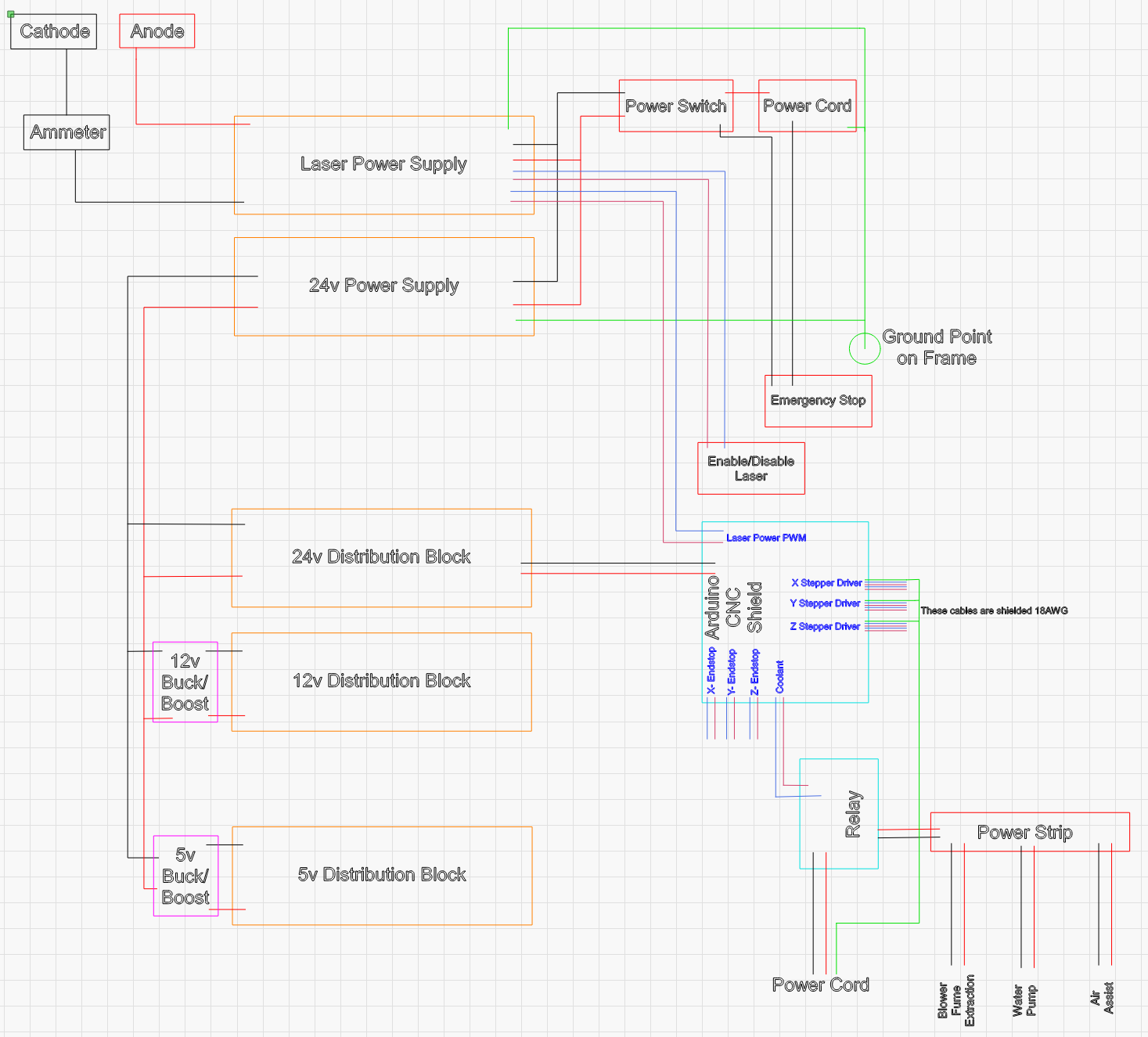
Do you have a schematic of the build?
Noise problems like this are hard to find. You just have to start “trying stuff” until you get a hint of the source of the noise.
You never know with noise but:
Unless the connection is open I doubt the problem is the cathode ground as there is very little energy in that loop.
I doubt the problem is in the LPS an open ground inside would render the Laser inop. Be careful if you open it there are lethal voltages inside and out.
Noise could be radiated or conducted. In my experience with these situations, it’s usually conducted
Usually, this kind of noise is caused by a ground loop in the supply.
Some practices to eliminate noise:
Make sure that the ground of all supplies returns to a common point and does not daisy chain fom load to load.
Improperly grounded shielded cable can exacerbate noise.
High voltage devices can capacitively couple into close wiring creating noise. Keep wires away from the anode connection and the tube.
Motors are also a source of noise so keep control signals away from motor wiring.
High current wires mixed inside of a wiring bundle can capacitively & inductively couple to and control signals in that same bundle.
When thinking about noise treat the power connections as control signals
Do not bundle high current wiring with low current/voltage control signals
Use twisted pair when routing control signals
Run the ground of each DC supply independently and directly to a bolt in the frame near the supplies. Keep all ground wires as short and large a gauge as reasonable. I.e. do not run ground leads across the machine.
Ground the mains to the same frame but near the plug.
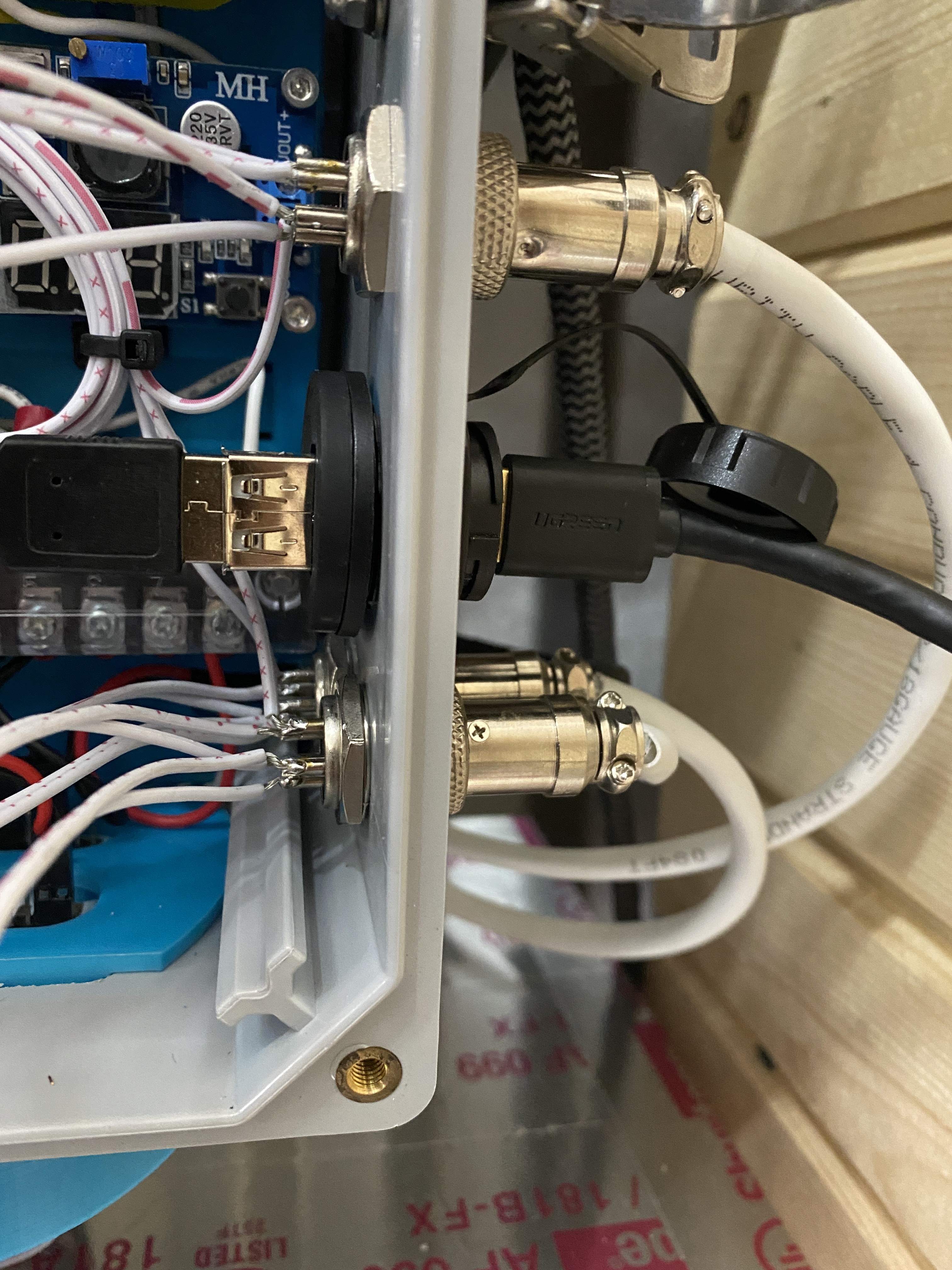
Aviator connectors. Slightly concerned about the connections on the inside of the box as they are a little exposed. I’m not sure how others have done up these connections.
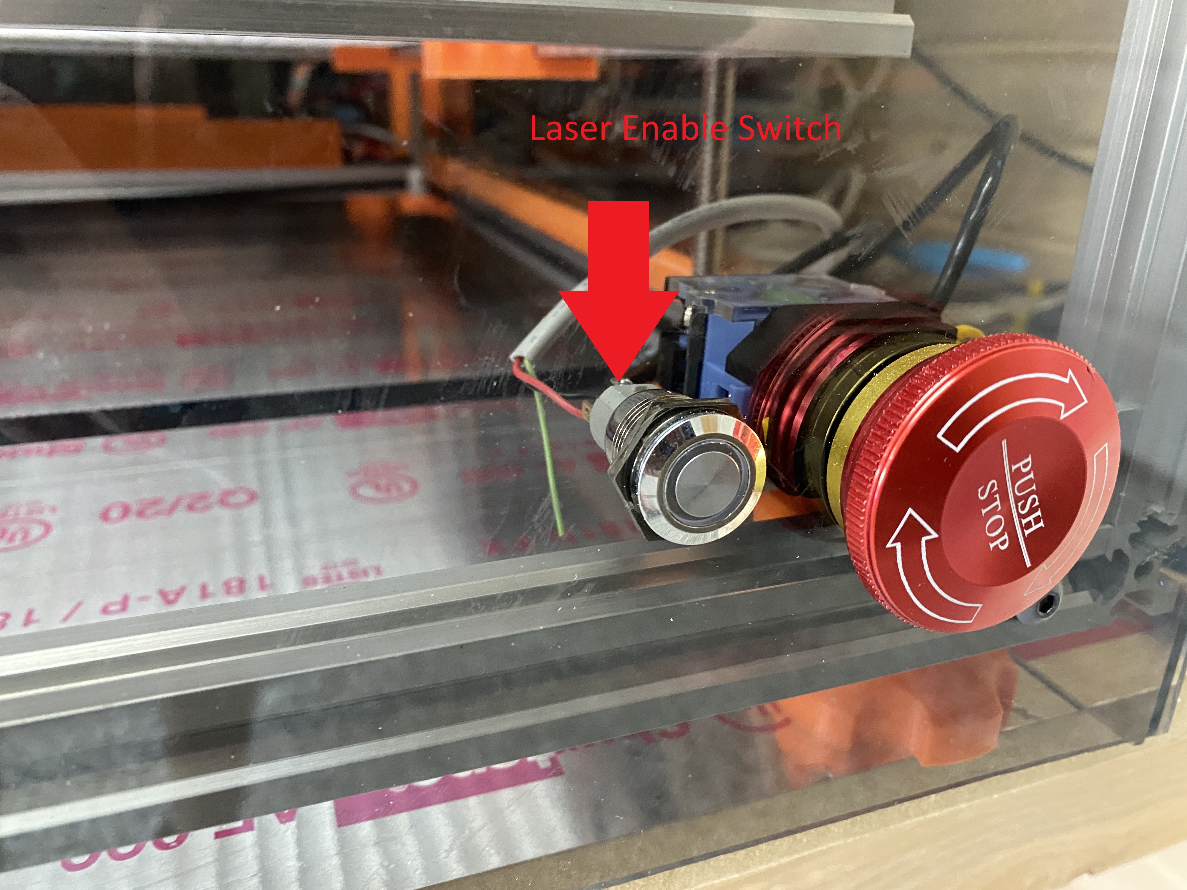
Wiring for this: I have a manual enable switch on the Laser Power Supply.
You can see the Laser Power Supply side of this connection labeled in one of the photos above. This leads to the switch shown in the image below. It’s really the water protection switch, I’m just using it for enable/disable.
Wiring for Arduino ground
This, I do not have nor am I aware of where or how to connect. This very well could be the issue. Where does the Arduino CNC Shield V3 have a connection for this?
Do you have a schematic of the build?
I guess LightBurn has some other uses:
Run the ground of each DC supply independently and directly to a bolt in the frame near the supplies. Keep all ground wires as short and large a gauge as reasonable. I.e. do not run ground leads across the machine. Ground the mains to the same frame but near the plug.
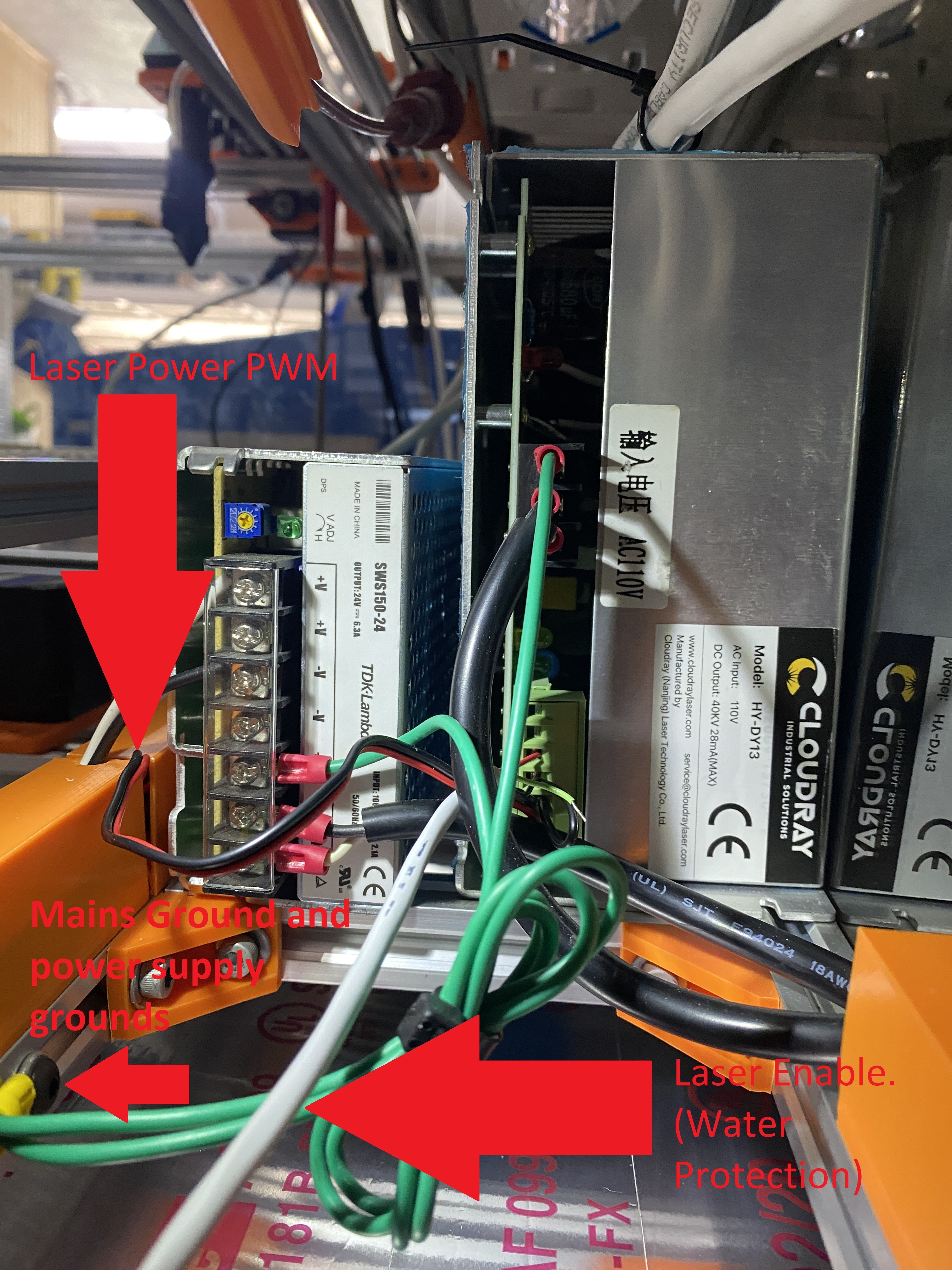
I have labelled the images above. I do believe this is how I have the machine setup.
This is interesting. The high voltage stuff does come close to the laser power pwm line. The stepper motor wiring has been drawn as far away as possible from the high voltage stuff.
This is a lot to take in. Let me know what you think.
Edit: Updated Laser Schematic with Enable/Disable Switch
There is no ground coming from the IEC socket in your photo.
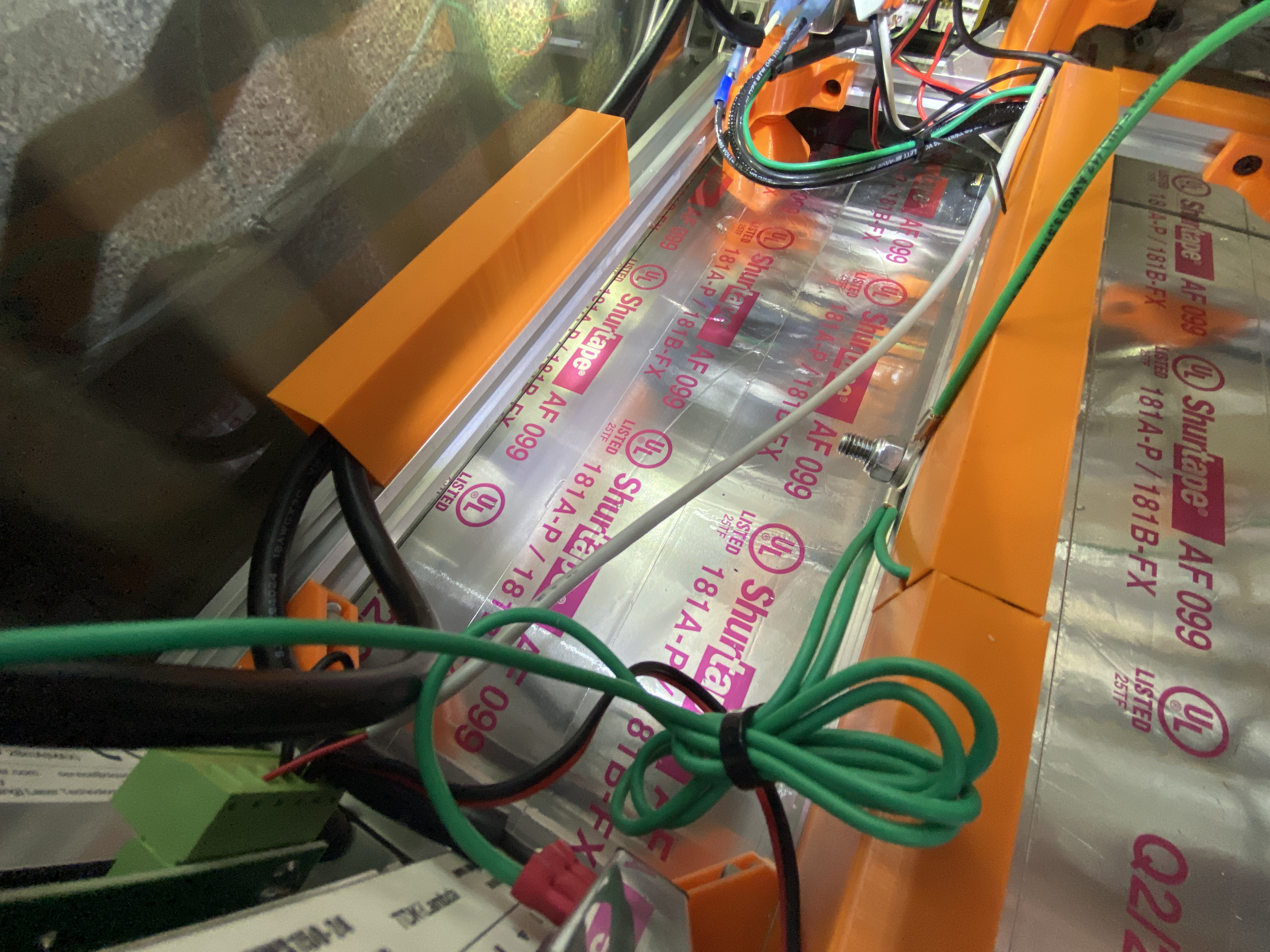
I can see that the two grounds from the PSUs are bolted to the frame, but there is no ground coming from the right side where the two AC/AC wires are coming from.
The two power supplies should be directly wired to the ground of the IEC socket.
A ring terminal bolted to an anodized aluminium extrusion with a captive nut won’t make a good connection.
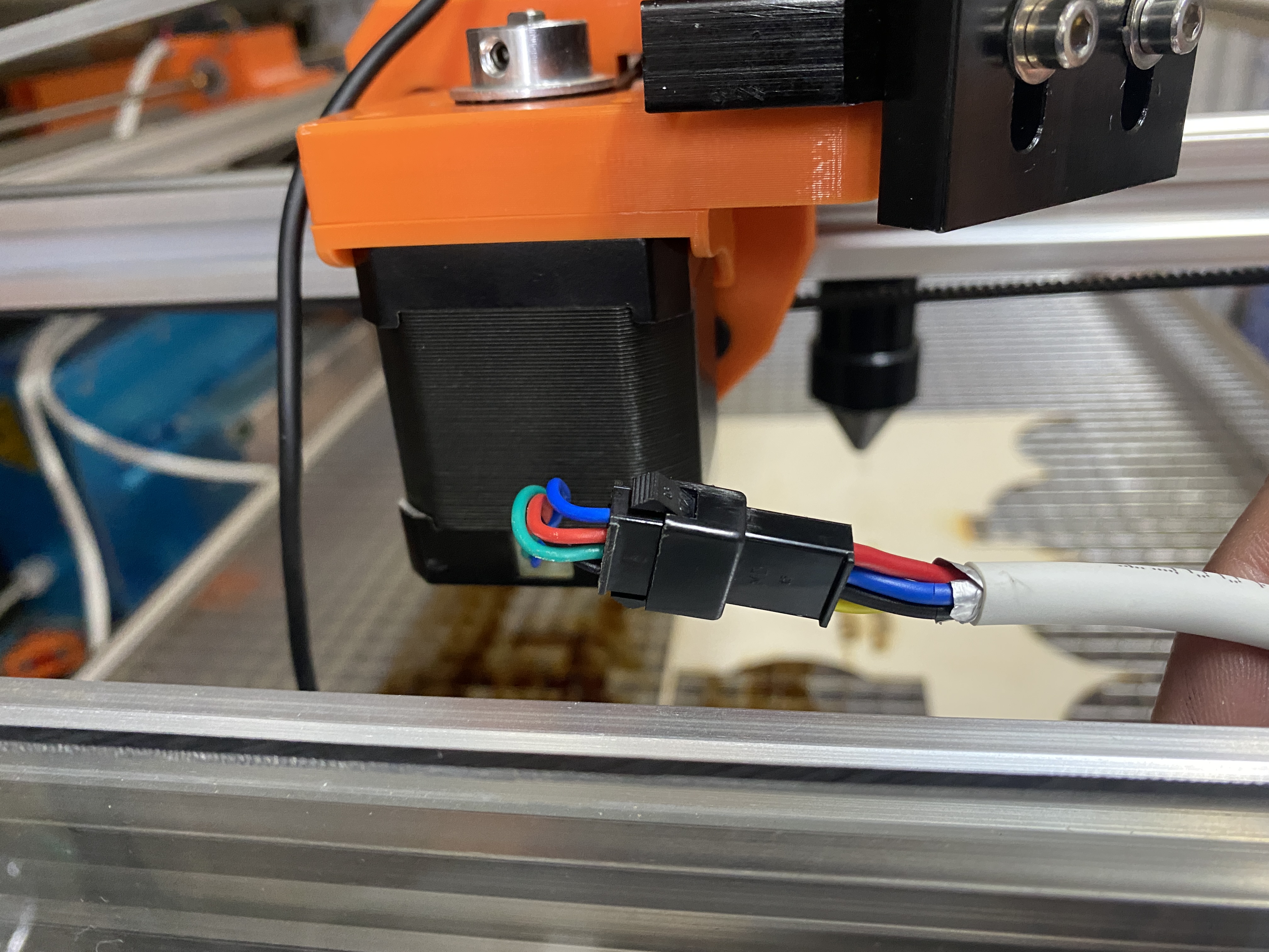
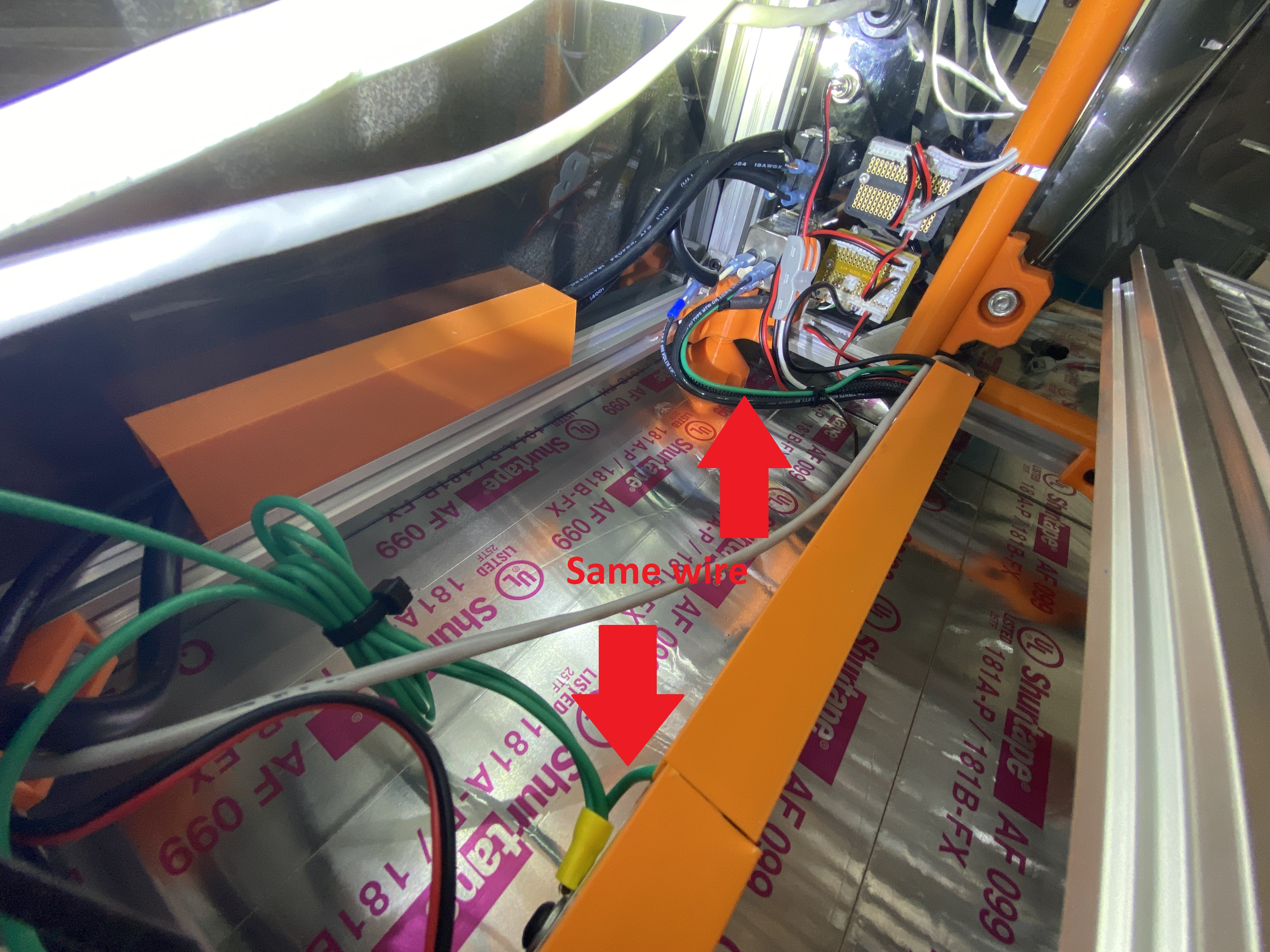
@tomatsu Here is another angle that shows that all three wires are in actually crimped together and then using a t-nut, bolted to the frame of the machine.
How do recommend grounding to the aluminum extrusion?
In the interim, I have redone the ground point. I drilled a hole through the aluminum extrusion and put a bolt through it with a washer and a lock nut. I sanded the surface prior to bolting it tight.
I also added a new ground wire to go from the main ground point to inside the electronics enclosure for the stepper motor wiring grounds. Here is the revised wiring schematic, just a small change, but maybe it was causing a ground loop.
To my dismay, no of the above helped. The X-axis shifted and the Z-axis is moving upwards slightly when it shouldn’t be moving at all. This of course eventually leads to the laser head crashing into the work material and really botching everything…
The problem won’t be interference with the power driving the steppers. It will a problem with the logic driving the stepper drivers. You just see the results of that interference in logic with stepper moves, but the problem isn’t the wiring to the steppers themselves, I’m quite confident.
Keep all the logic in particular well away from the HV.
What do you mean when you say logic. Are you talking about the software logic? If you do mean software logic, how do I keep that away from the high voltage stuff?
The wires that carry signals, rather than the wires that carry power. E.g. endstops, switches, the laser enable from the arduino to the LPS.
Looking at your circuit diagram, be aware that many power supplies connect ground to the negative DC supply. You can test that with a multimeter. This may be giving you ground loops that you don’t recognize.
@mcdanlj thank you, I did identify that my 24v DC power supply did have ground connected to the negative rail. I disconnected the ground wire, and tried to burn something. Same story. Wonky behavior. I’m not sure what to do to properly ground this power supply now.
I also pulled the guts out of my controller box separating high voltage (24v) from my logic connections. This made the stepper motor behavior even worse than it was before. I’m actually kinda glad something has changed. Everything I’ve been doing up until now has yielded no change, so this was somewhat exciting. Just in the wrong direction of exciting
I would shorten the green grounding wire that goes from the LPS and DC supply to the frame, [that is bundled] unless there is a reason for the extra length.
I don’t see anything connected to V- of the 24V supply. Are the DC ground and AC safety ground on that supply connected internally?
How is the DC supply to the Arduino connected and routed?
How is the DC ground on the LPS connected & routed?
Post a picture showing the LPS connectors from the top if possible.
Post pictures of the ANODE wires routing
More detail on what strange is? How is this manifesting in the operation?
I am betting that the interference is not the steppers and their wiring but rather that’s a secondary effect of the controller’s grounding or supply being susceptible to noise.
If the PWM line was being impacted by the noise I don’t think this would directly impact the operation of the stepper.
The arduino controller itself is glitching from noise from power rails or signal lines — commanding the steppers to do the wrong thing
The signals from the arduino controller to the stepper drivers are noisy and introducing unintended transitions on at least one line that aren’t commanded by the arduino.
Since Z is moving, at least the Z STEP line has to be glitching for one reason or another. Glitching EN or DIR wouldn’t help if Z isn’t supposed to be moving at all.
The X artifacts could be glitching any or all of X STEP, EN, or DIR.
I really want to answer all of @donkjr 's questions, but I’m not sure they will be relevant after this post.
OK, a lot has happened this morning. I thought extensively about this on my pillow last night.
Keep these key points of my setup in mind:
The LPS is mounted to the frame of the machine.
The 24V DC power supply is mounted to the frame of the machine.
The 24V DC power supply earth ground, negative (-), and enclosure are all tied together.
Using a multi-meter I found there was continuity between the 24V DC power supply case, negative (-), earth ground and the LPS case.
In my opinion, the DC power supply is junk. I eliminated it from the setup. I unmounted the LPS from the machine and set it on a piece of wood (now there is only one earth ground point). I grabbed my benchtop power supply that has a real earth ground, plugged it into the same outlet as the laser machine (same earth ground), and then connected that to my 24V distribution block that powers the Arduino and CNC shield.
and… I was able to burn something.
Now, my entire machine is in ruins I have much nicer 24V DC power supply on order.
After the first successful burn, I wanted to see how far I could push the machine. I upped the speed and acceleration.
X and Y Acceleration: 2000mm/sec2
X and Y Speed: 200 mm/sec
With the higher speed and acceleration values I am seeing a few missed steps here or there. I do not believe I am exceeding the specs of the steppers or the machine. I do think that the Arduino is the cause and noise in the controller is the source, I just don’t know how to prove it.
This is complicated and I think that the earlier questions and suggestions are still relevant.
Clearly, you have a ground(s) loop somewhere. The fact that there are still a few missed steps suggests that although you are making progress you haven’t really isolated the source(s).
All of the power supply frames should be tied to the frame of the machine as this is a safety ground. If disconnecting them from the frame creates + results then somehow these circuits are creating a loop that is affecting the logic. Like a shift in the DC supply voltage. Frame ground is for safety and should not be impacting the logic.
Sometimes power supplies have the negative tied to the frame internally. This does not mean that the supply is poorly made. I have seen cases where the logic [power] and frame ground need to be tied together and others where it creates problems.
Check the internals of the supply and see if there is a point to disconnect the two. Most of the time solving the problem by disconnecting these from each other suggests the source is actually elsewhere.
Think of grounding problems as high-frequency perturbations in the supply voltage. Modern chips run in the ns range so high-frequency shifts in the DC supply can dramatically affect the operation and you cannot detect them with common tools.
Recheck your grounding hygiene:
Ensure that all power source frames are tied to the frame.
Make sure all the extrusion frame sections are actually electrically tied together.
Make sure all power supply grounds are tied directly to one point on the frame. One wire from each. Make as short as possible
Make sure all loads have both + and - power connections back to their supplies. One set for each.
I am still betting the noise source is the Arduino’s power and grounding.
By chance do you have an ossiloscope?
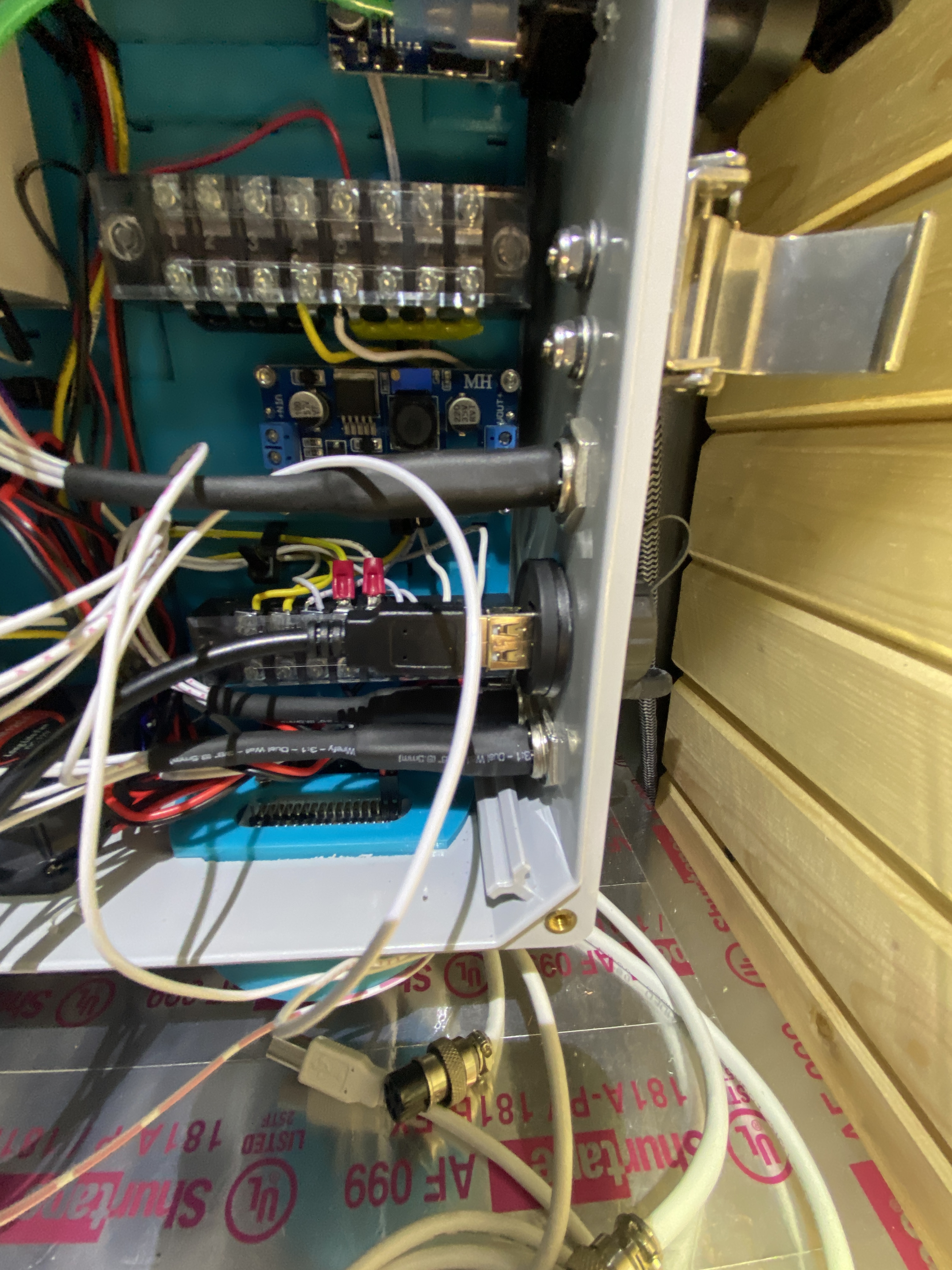
The V- connection is obstructed in this photo behind my big red arrow. If you look closely you can see the edge of a black wire in the 3rd from top V- lug.
The CNC Shield is connected via the 24v DC V- and V+ that is depicted in the image above. It is routed out of the machine enclosure and into an electronics enclosure that is separate from the machine enclosure. It is grouped with the low voltage logic wiring (x,y, and z endstops).
This post visually represents the strange behavior. In few words, when X is supposed to move left, it moves right, then 2 seconds later it moves left when it should move left, two more seconds it moves right when it should move left. Sometimes stopping altogether when it should be moving. It is erratic behavior.
I’ll ask this question again. How is an Arduino with the CNC shield supposed to be grounded? It only has a negative (-) and positive(+) lug.
This is interesting. I imagine it is OK to have a distribution block located elsewhere and have everything run to that… correct me if I am wrong here.
I am mobile so my posts for the next few days may be ugly.
This is a hard question to answer accurately. If all the loads come to a single block and then a single wire goes to the supply that could be a culprit especially if the wire is to small a gauge.
I just realized that we jumped into a grounding problem and didn’t rule out a bad Arduino, shield or code?
Please post pictures and manuf. info of the Arduino, shield and it’s local wiring.
James Harding via Maker Forums Monday, September 5, 1:36 PM
I’ll ask this question again. How is an Arduino with the CNC shield supposed to be grounded? It only has a negative (-) and positive(+) lug.
I can better answer this when I see the board and shield setup.
I would get a buss or connection to as many ground connections as possible.
Look at the Arduino power with your scope while this problem happens.