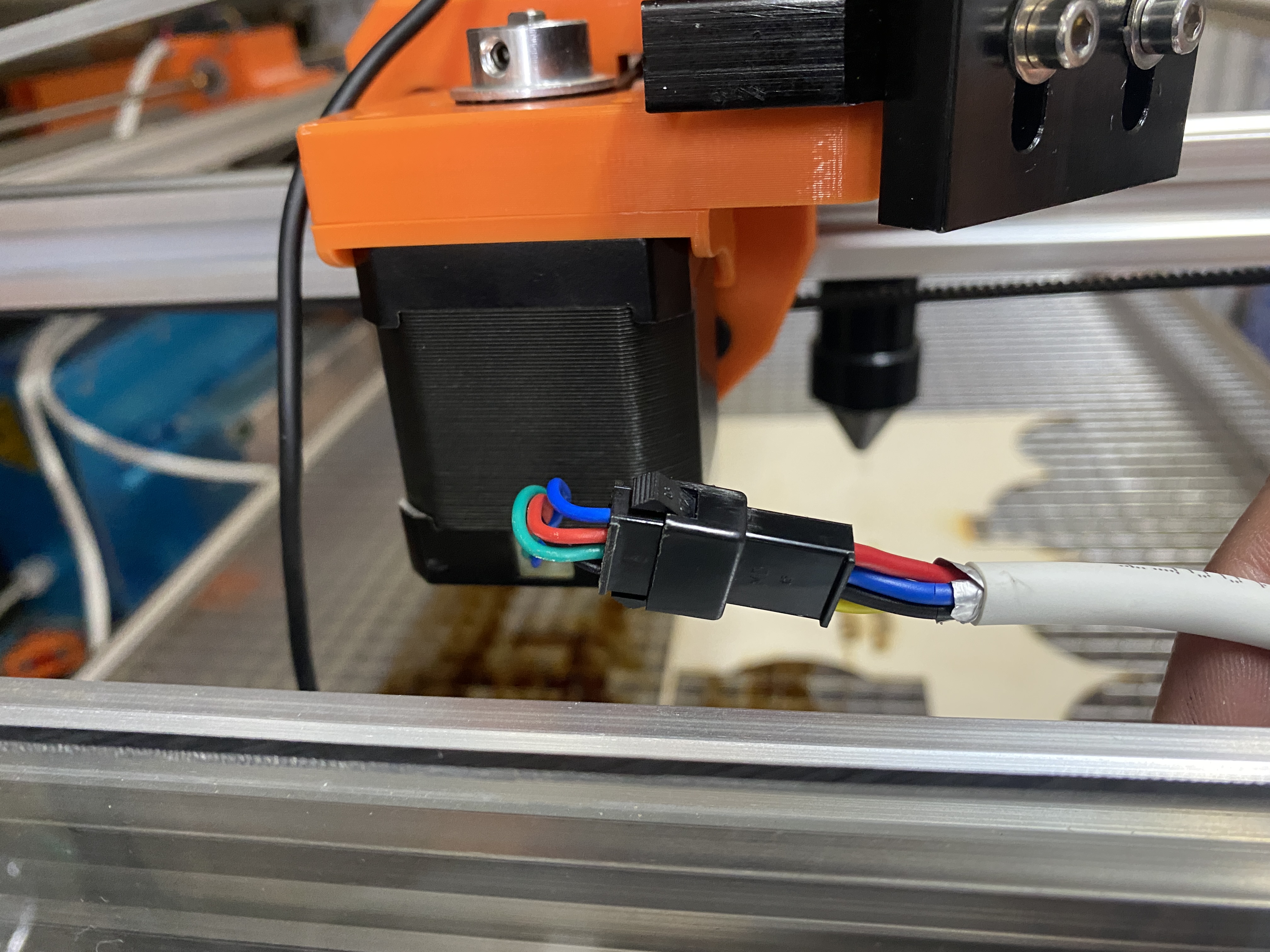
I have a new custom laser build. I started out with some really basic cables for my stepper motors (X, Y, and Z axes). It seemed like I was picking up some noise on my stepper motors as they were acting a little strange. I upgraded the cabling to a shielded cable and some aviation connectors.
The problem is substantially worse now. I have a manual enable switch on the Laser Power Supply. When I disable the Laser Power Supply with this switch and run a job, the stepper motors work perfectly, no issues at all. If I flip the enable switch at any point, the laser will start firing as it should, and the stepper motors will go crazy.
Grounding: Both the laser power supply and my separate 24v power supply are grounded to the 3rd prong of the main power cord. This ground is also attached to the frame of the laser machine. I have verified that continuity to ground spans across the whole frame of the laser. There is a ground wire in my stepper motors shielded cable that is also attached to ground.
Not sure what is causing this interference / noise with the stepper motors. Any ideas on where to take a look?
Make sure the L+ and L- wires are close together to reduce the size and effectiveness of this loop antenna. Also try to keep some distance between these two wires and the low-voltage stuff.
You have pretty much isolated it to something lps related. Double check the cathode return to ground. If this is not properly grounded you can have some higher voltages that expected creep up…
Most of the other items you have checked.
Do you have a mA meter and is it working properly?
Yes, I do have a mA meter and it does appear to be working correctly. The leads to the mA meter are long, about a meter or so.
I did have to solder longer leads to the cathode ground. I put silicone infused heat shrink around my solder joints. This line does run right along the frame of the machine for pretty much it’s entire length.
I will check the return ground to see if it’s shorting.
I don’t think it’s a length issue, especially with the cathode, as it’s at or near ground potential anyway, or it should be…
It sounds like the lps is giving you the issue, so I was hoping that maybe a poor return on the lps could be causing it. The resistance has to be pretty high to cause a high potential there…
Take care if you decide to get into the ‘black box’ if it’s the lps, give it a number of hours do discharge. Most of the time there is no path to ground, so they can be hot for a while…
I hate to see you fooling with this if it’s not a ‘normal’ lps…
You mentioned the problem is caused when you power up the lps.
I was suggesting to check the cathode return lead. That can cause high voltages to occur and unstable operation…
I was warning you about the high voltages will remian for a long time within the lps… hence the ‘no path to ground’ does not allow the high voltage to ‘drain’ off… it just take time…
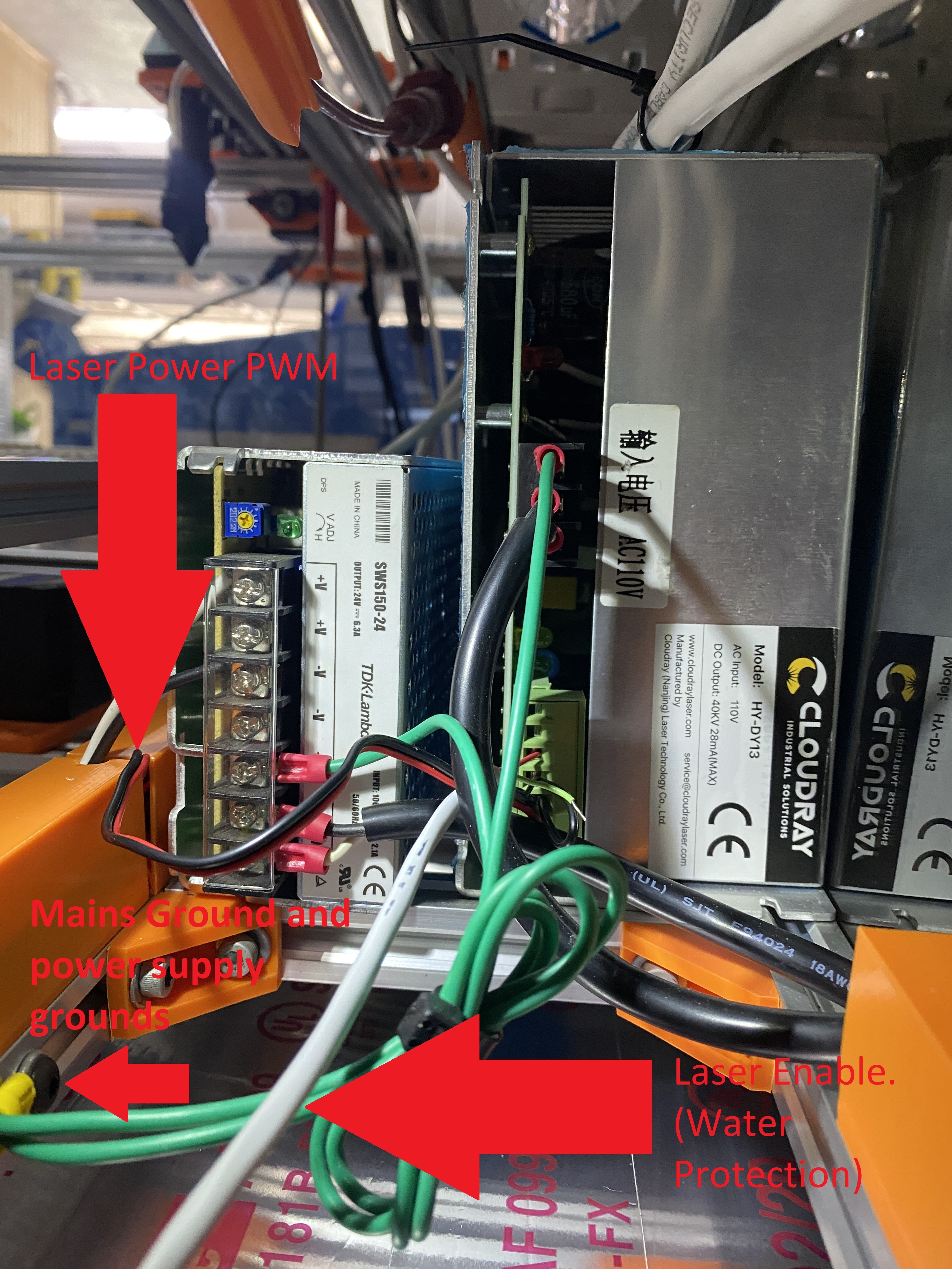
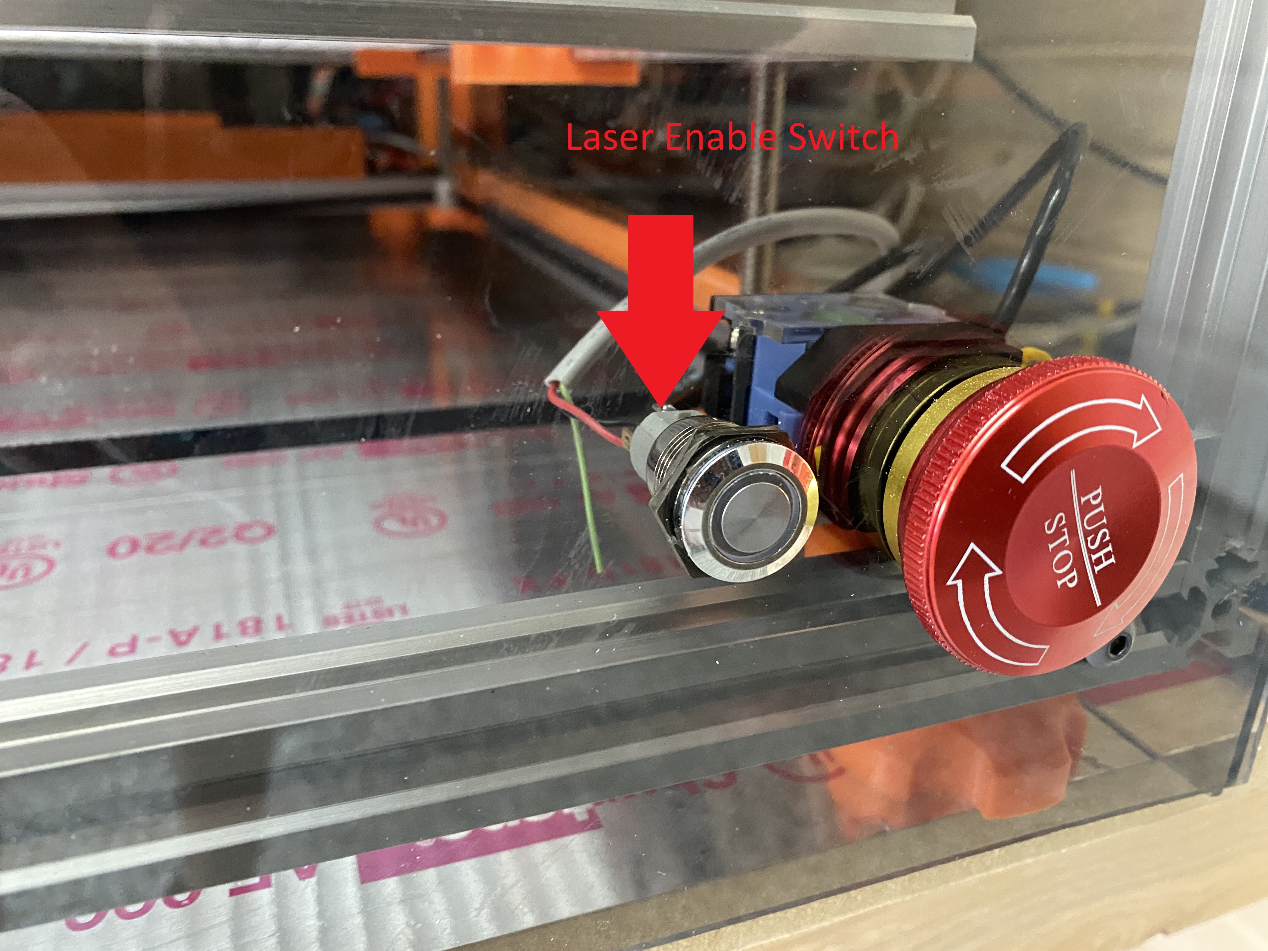
Wiring for this: I have a manual enable switch on the Laser Power Supply.
Wiring for Arduino ground
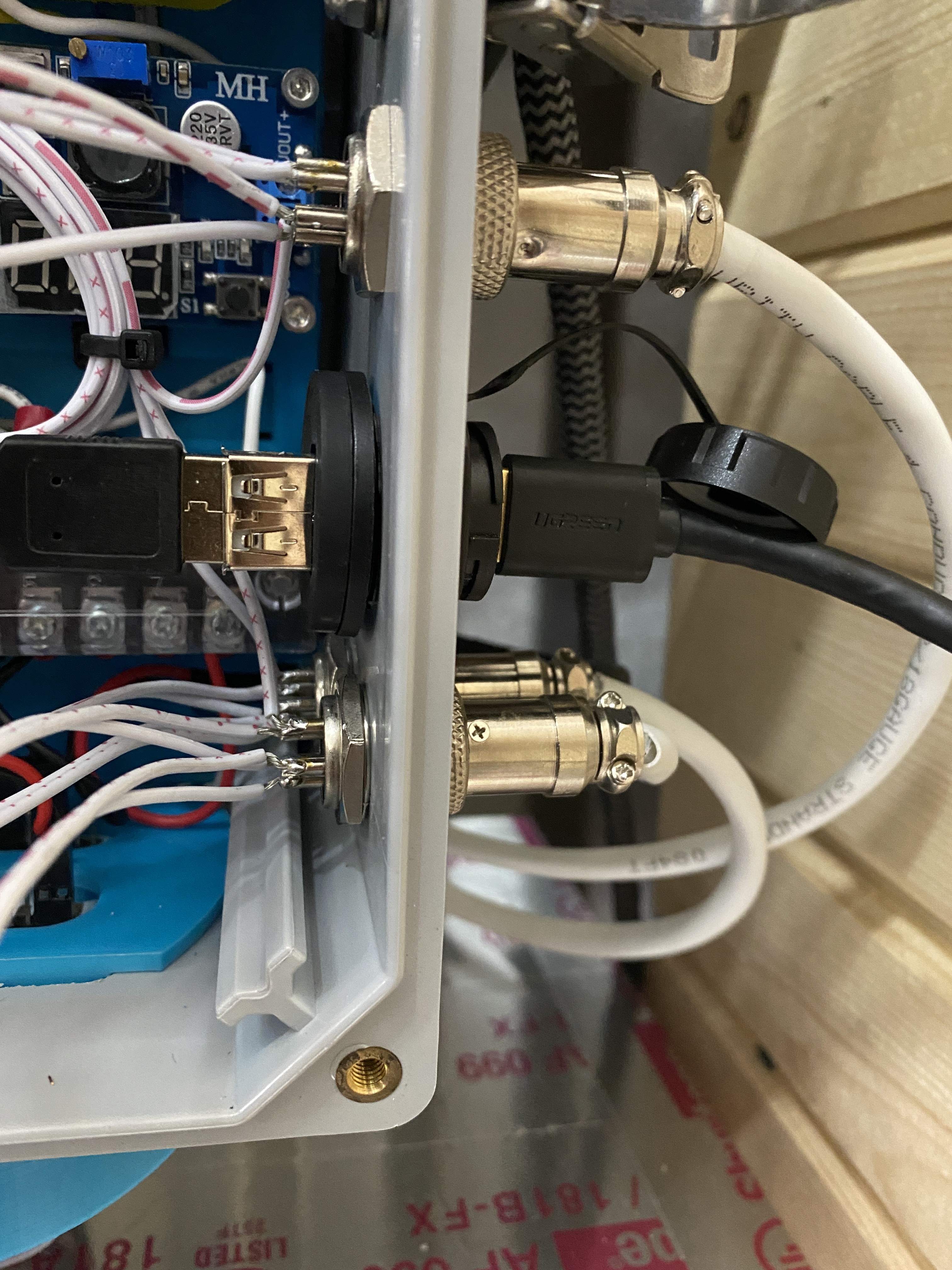
Connector side of the LPS
Do you have a schematic of the build?
Noise problems like this are hard to find. You just have to start “trying stuff” until you get a hint of the source of the noise.
You never know with noise but:
Unless the connection is open I doubt the problem is the cathode ground as there is very little energy in that loop.
I doubt the problem is in the LPS an open ground inside would render the Laser inop. Be careful if you open it there are lethal voltages inside and out.
Noise could be radiated or conducted. In my experience with these situations, it’s usually conducted
Usually, this kind of noise is caused by a ground loop in the supply.
Some practices to eliminate noise:
Make sure that the ground of all supplies returns to a common point and does not daisy chain fom load to load.
Improperly grounded shielded cable can exacerbate noise.
High voltage devices can capacitively couple into close wiring creating noise. Keep wires away from the anode connection and the tube.
Motors are also a source of noise so keep control signals away from motor wiring.
High current wires mixed inside of a wiring bundle can capacitively & inductively couple to and control signals in that same bundle.
When thinking about noise treat the power connections as control signals
Do not bundle high current wiring with low current/voltage control signals
Use twisted pair when routing control signals
Run the ground of each DC supply independently and directly to a bolt in the frame near the supplies. Keep all ground wires as short and large a gauge as reasonable. I.e. do not run ground leads across the machine.
Ground the mains to the same frame but near the plug.
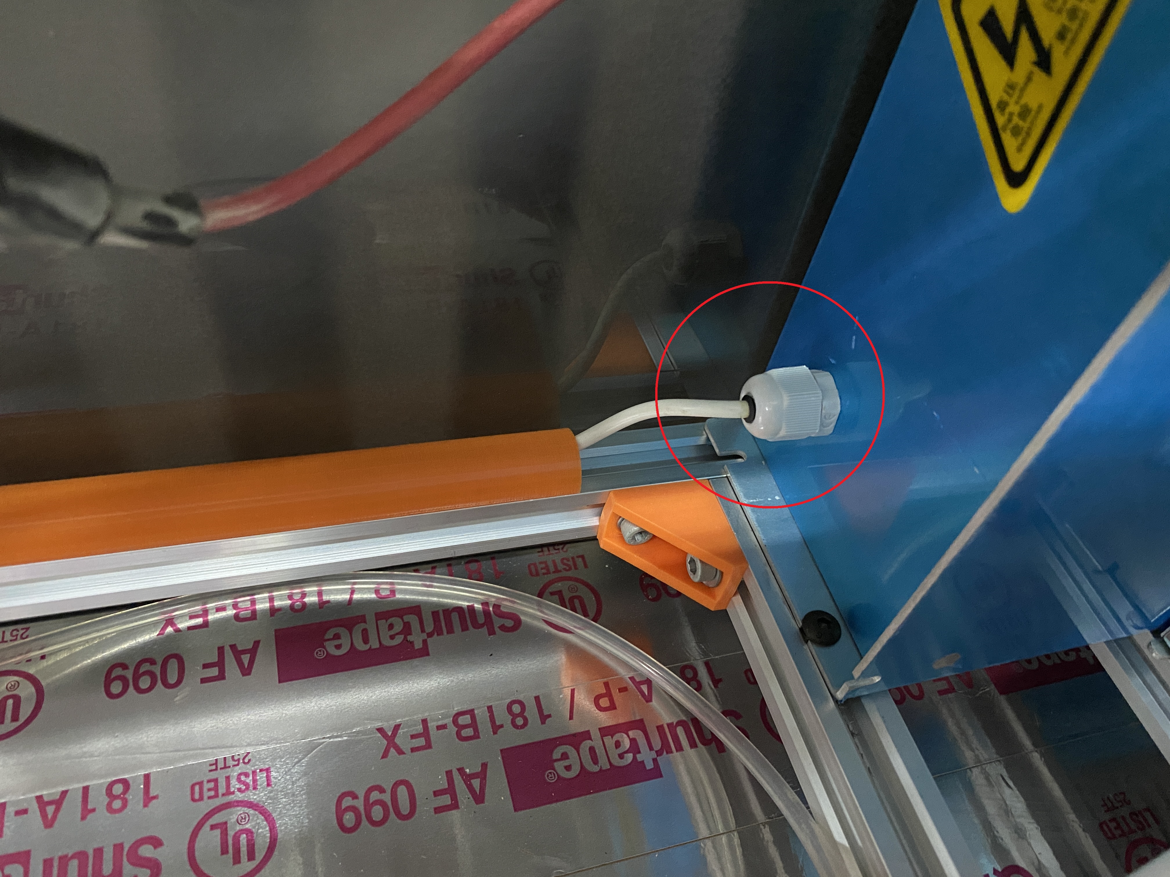
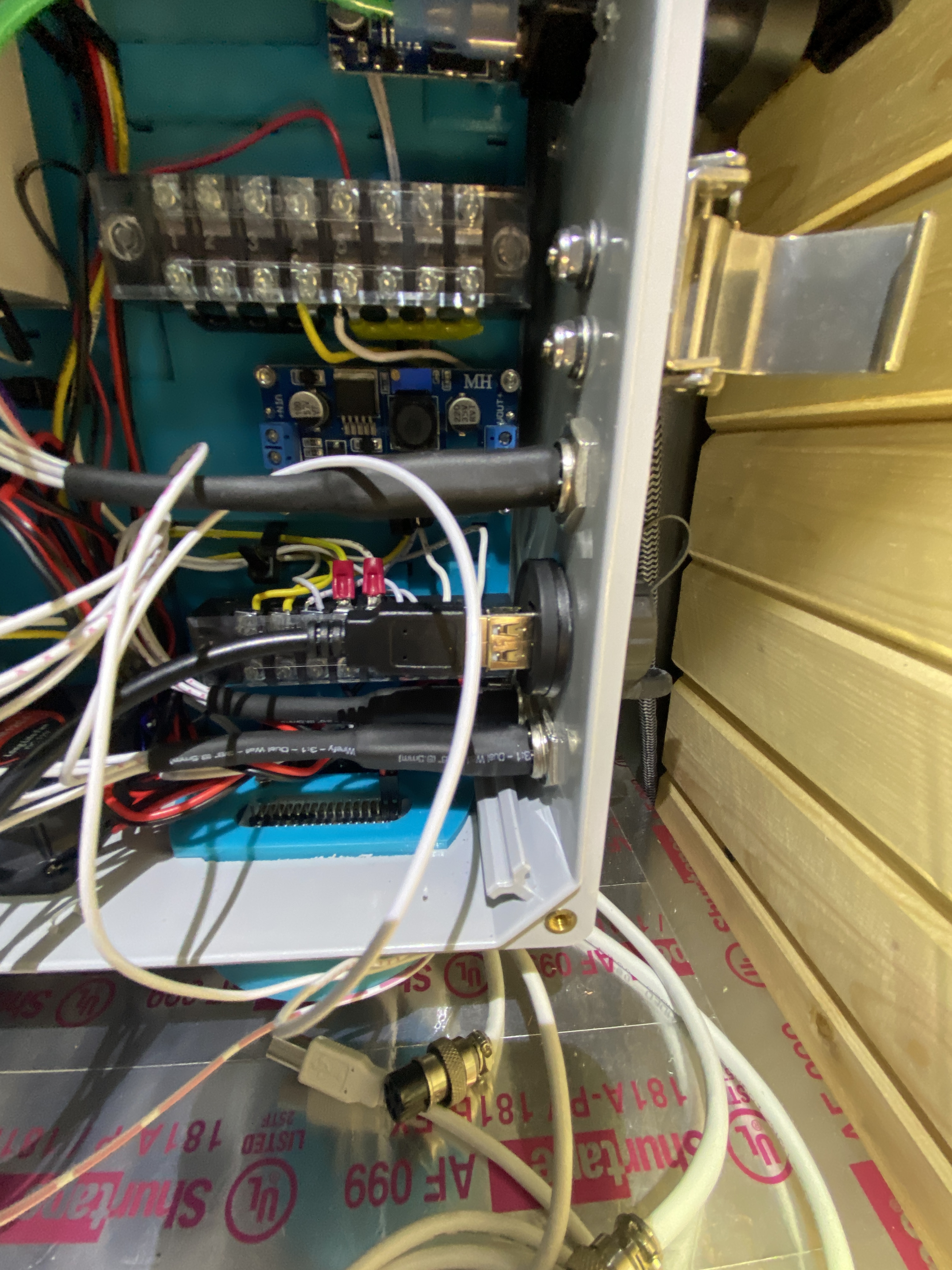
Aviator connectors. Slightly concerned about the connections on the inside of the box as they are a little exposed. I’m not sure how others have done up these connections.
Wiring for this: I have a manual enable switch on the Laser Power Supply.
You can see the Laser Power Supply side of this connection labeled in one of the photos above. This leads to the switch shown in the image below. It’s really the water protection switch, I’m just using it for enable/disable.
Wiring for Arduino ground
This, I do not have nor am I aware of where or how to connect. This very well could be the issue. Where does the Arduino CNC Shield V3 have a connection for this?
Do you have a schematic of the build?
I guess LightBurn has some other uses:
Run the ground of each DC supply independently and directly to a bolt in the frame near the supplies. Keep all ground wires as short and large a gauge as reasonable. I.e. do not run ground leads across the machine. Ground the mains to the same frame but near the plug.
I have labelled the images above. I do believe this is how I have the machine setup.
This is interesting. The high voltage stuff does come close to the laser power pwm line. The stepper motor wiring has been drawn as far away as possible from the high voltage stuff.
This is a lot to take in. Let me know what you think.
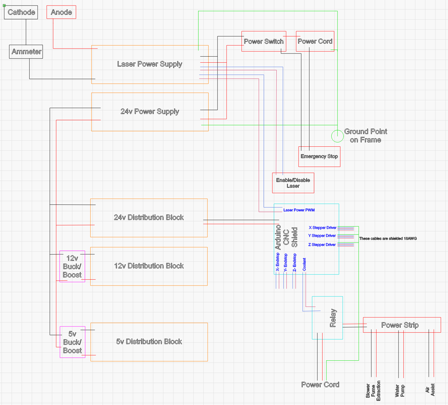
Edit: Updated Laser Schematic with Enable/Disable Switch
There is no ground coming from the IEC socket in your photo.
I can see that the two grounds from the PSUs are bolted to the frame, but there is no ground coming from the right side where the two AC/AC wires are coming from.
The two power supplies should be directly wired to the ground of the IEC socket.
A ring terminal bolted to an anodized aluminium extrusion with a captive nut won’t make a good connection.
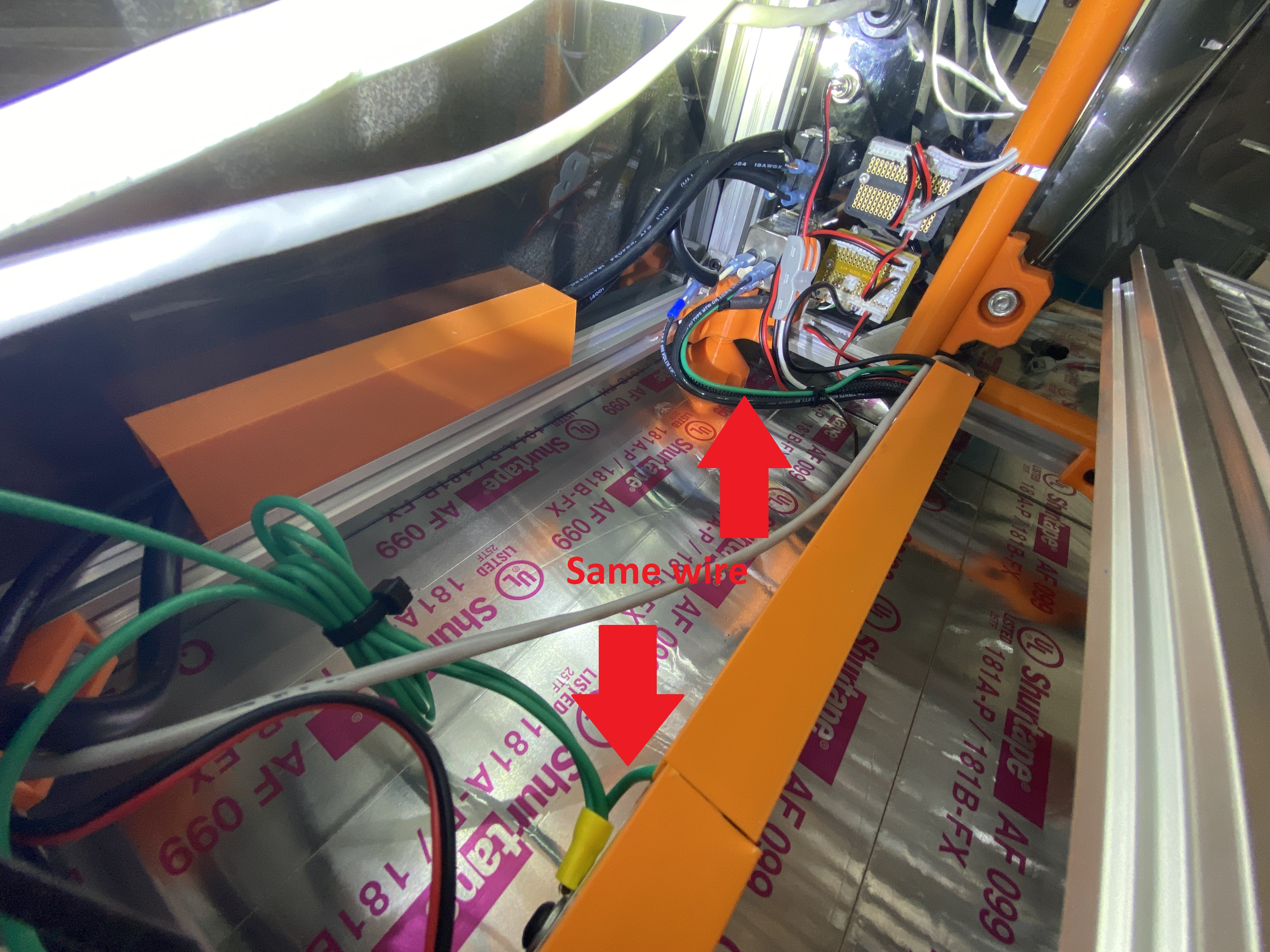
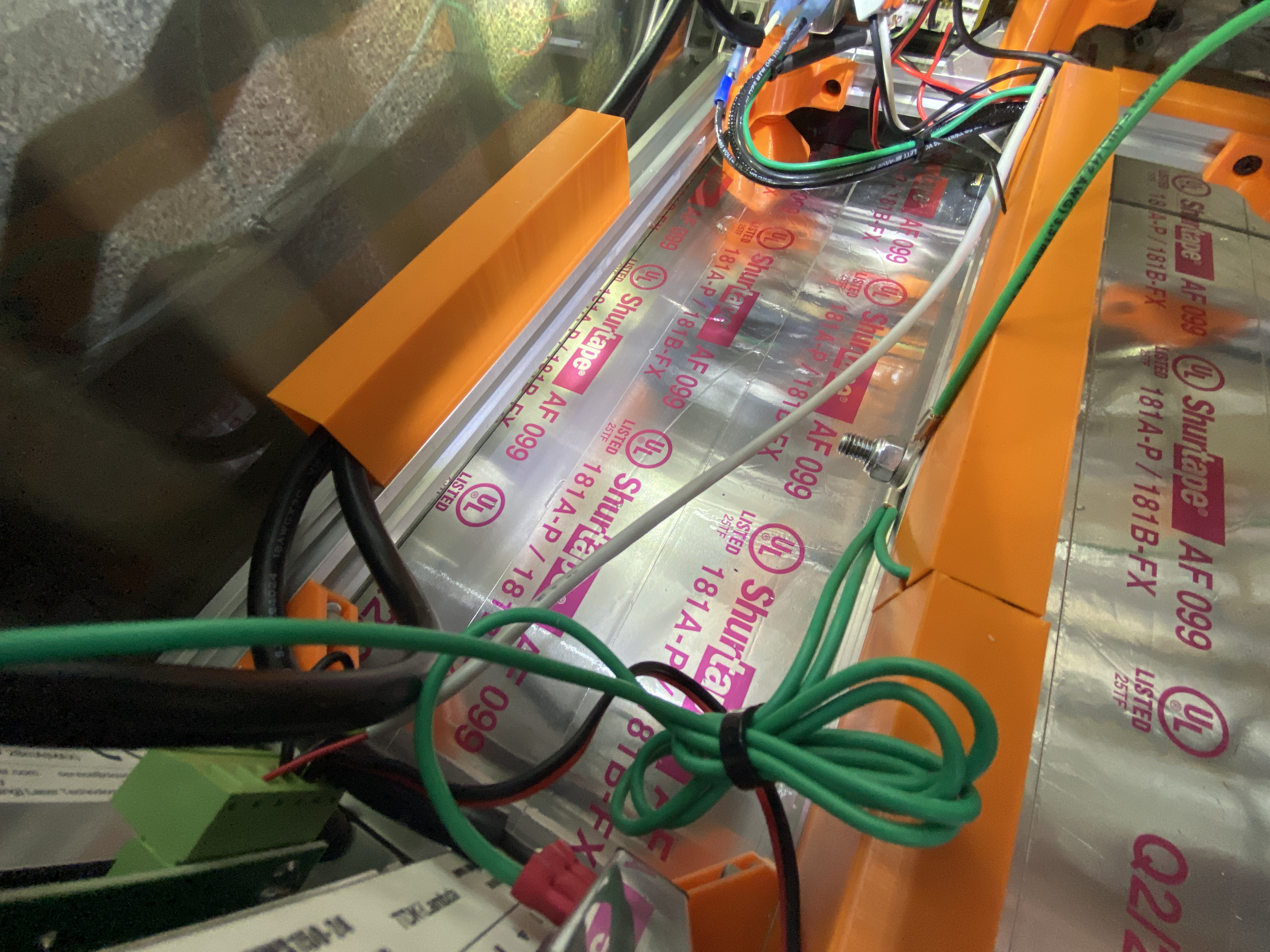
@tomatsu Here is another angle that shows that all three wires are in actually crimped together and then using a t-nut, bolted to the frame of the machine.
How do recommend grounding to the aluminum extrusion?
In the interim, I have redone the ground point. I drilled a hole through the aluminum extrusion and put a bolt through it with a washer and a lock nut. I sanded the surface prior to bolting it tight.
I also added a new ground wire to go from the main ground point to inside the electronics enclosure for the stepper motor wiring grounds. Here is the revised wiring schematic, just a small change, but maybe it was causing a ground loop.
To my dismay, no of the above helped. The X-axis shifted and the Z-axis is moving upwards slightly when it shouldn’t be moving at all. This of course eventually leads to the laser head crashing into the work material and really botching everything…
The problem won’t be interference with the power driving the steppers. It will a problem with the logic driving the stepper drivers. You just see the results of that interference in logic with stepper moves, but the problem isn’t the wiring to the steppers themselves, I’m quite confident.
Keep all the logic in particular well away from the HV.
What do you mean when you say logic. Are you talking about the software logic? If you do mean software logic, how do I keep that away from the high voltage stuff?
The wires that carry signals, rather than the wires that carry power. E.g. endstops, switches, the laser enable from the arduino to the LPS.
Looking at your circuit diagram, be aware that many power supplies connect ground to the negative DC supply. You can test that with a multimeter. This may be giving you ground loops that you don’t recognize.
@mcdanlj thank you, I did identify that my 24v DC power supply did have ground connected to the negative rail. I disconnected the ground wire, and tried to burn something. Same story. Wonky behavior. I’m not sure what to do to properly ground this power supply now.
I also pulled the guts out of my controller box separating high voltage (24v) from my logic connections. This made the stepper motor behavior even worse than it was before. I’m actually kinda glad something has changed. Everything I’ve been doing up until now has yielded no change, so this was somewhat exciting. Just in the wrong direction of exciting