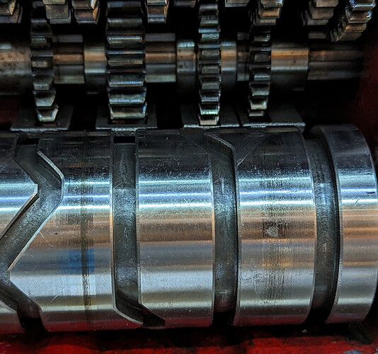
Characterizing the quick change gearbox on my G0709 lathe

I’ve been working on adding an electronic lead screw to my lathe — which those of you who follow me on Maker Forums Social may have seen me post about. I’m planning a build post when I’m finished, but in the meantime, I thought I’d post the results of a bit of a side project of understanding how the quick change gearbox on my G0709 lathe works.


Since I had the gearbox open to clean it, I decided to characterize it as completely as I can. I needed to do some of this to put it together correctly, and while I am about to convert to an electronic lead screw almost certainly driving this lathe for the rest of its life in ATW1 configuration (the maximum mechanical advantage, driving both the feed bar and lead screw), others might find this more useful.

Rotational domain definition​

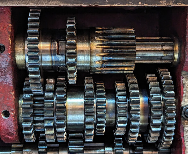
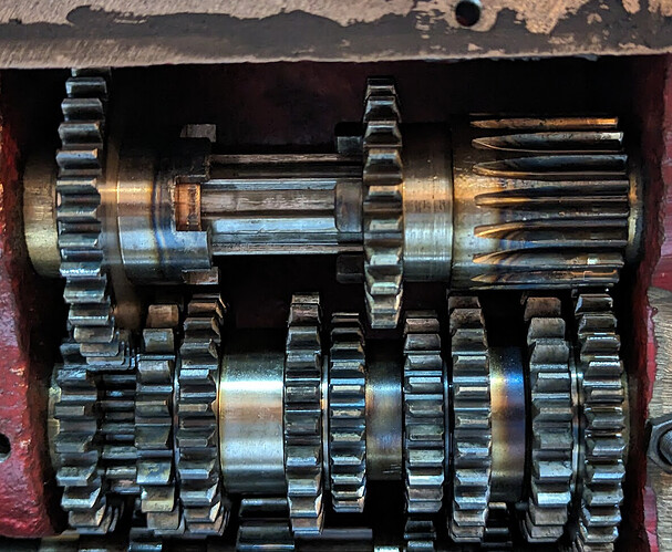
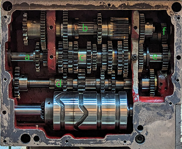
The manual doesn’t have names for this, so I have to make something up. There are six independent axes of rotation in the gearbox. The gearbox is driven from the change gears on the left, and drives both the lead screw at the top right and the feed screw at the bottom left. I’ll call these independent axes “rotational domains” and refer to them with lower-case letters a-f, since upper-case letters and numbers are both used for settings. They aren’t labeled strictly in order, because different configurations drive them in different orders.

  • Zone a: Input from the change gears; terminates at the first divider
  • Zone b: The entire topmost axis, through both dividers
  • Zone c: Coaxial with zone a, but terminating on each side at the dividers
  • Zone d: Connected from wall to wall; holds a driving gear from a engaged only in the C configuration, a series of four gears that engage with 8 of the 10 gears in zone c selected by the 1-8 setting cam at the bottom, an output gear to the right of the rightmost divider, and finally directly drives the feed bar out the right side.
  • Zone e: Coaxial with zones a and c, has one sliding gear that couples b to f (Y configuration), leaves f uncoupled (X configuration; drives only feed bar not lead screw), or couples d to f (W configuration)
  • Zone f: The lead screw output

Driving Orders​

The A/B/C and W/X/Y selectors affect the order in which the domains are driven. I denote x driving y as xy here.

  • A/B: a→b→c →d
  • C…Y: a→d→c →b→e→f (used only for the lead screw; in these configurations the feed bar turns at the same rate relative to the input regardless of R/S/T or 1-8 settings)
  • W: d→e→f
  • X: Drives only the feed bar (direct from d) without engaging the lead screw at all)
  • Y: Used only with C to drive only the lead screw (b→e→f)

Driving Ratios​

The A/B/C, R/S/T, W/Y, and 1-8 selectors choose gear ratios. The direction in which those ratios apply from input to output depends on the driving order selectors previously described. I use the actual gear tooth counts here and do not reduce ratios to “proper fractions”. This should help look up the gears in the manual and follow along.

A/B set the ratio of a:b

a b decimal
A 20 50 0.4
B 19 19 1.0

C sets the ratio of a:d

a d decimal
C 19 22 0.8636

R/S/T set the ratio of b:c which is either unity (1:1 or 19:38 in one direction or the other):

b c decimal
R 38 19 2.0
S 23 23 1.0
T 19 38 0.5

1-8 set the ratio of c:d

c d decimal
1 24 33 0.7575
2 27 33 0.8181
3 20 22 0.9090
4 22 22 1.0
5 23 22 1.0454
6 24 22 1.0909
7 26 22 1.1818
8 28 22 1.2727

W couples d:e 36:35 (1.0285) and e:f is permanently coupled 26:26 (unity)

Y couples b:e 35:35 (unity) and e:f is permanently coupled 26:26 (unity)

Configuration Close-ups​

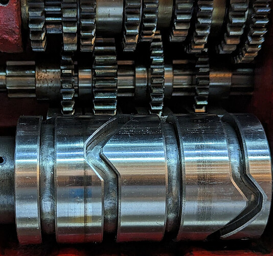
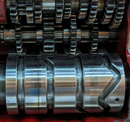
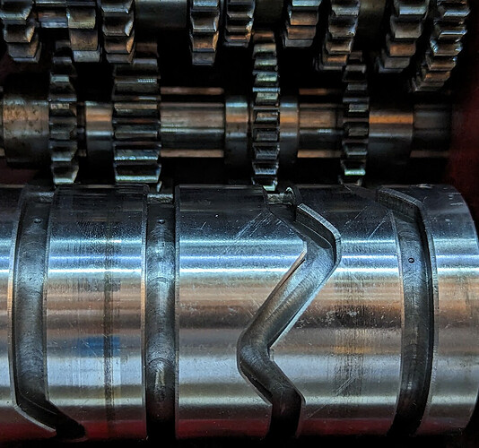
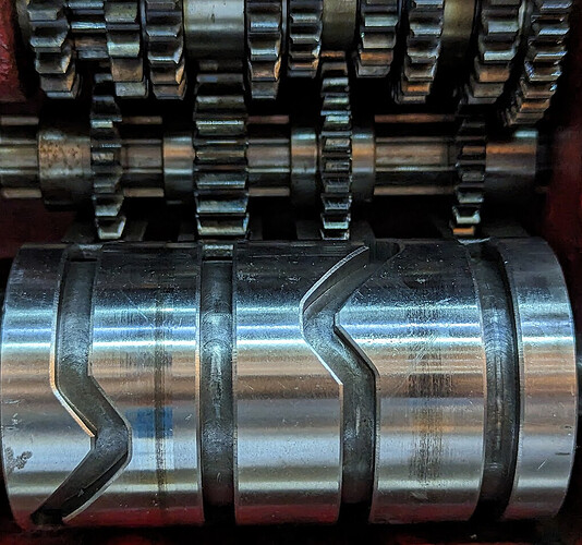
Here are pictures of the relevant section of the gearbox for each separate configuration option, with some description.

A/B/C Selector​

A​

Input a coupled to b domain 20:50

B​

Input a coupled to b domain 19:19

C​

Input a coupled to d domain 19:22

R/S/T Selector​

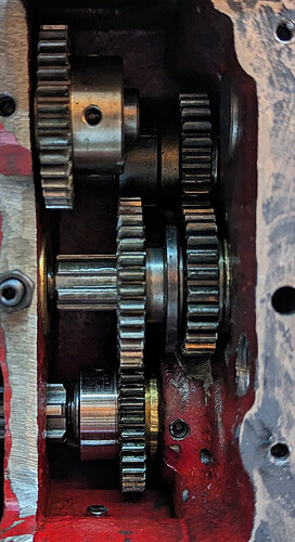
R​

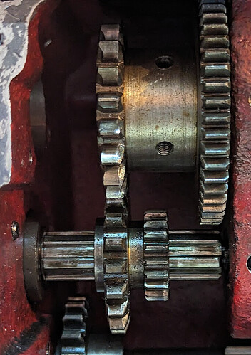
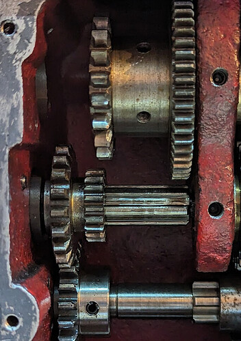
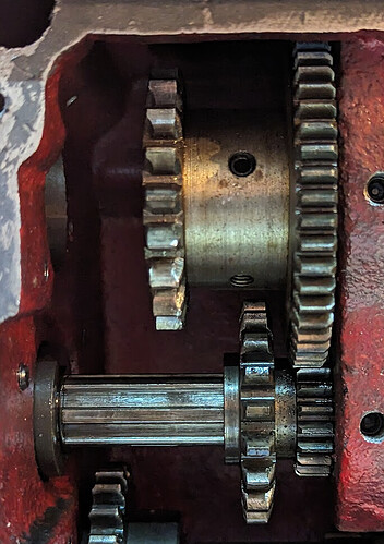
Note that the 38:19 pair are always engaged with each other; in position R, a castellated pair couples the spline of axis b to the otherwise freely-rotating 38-tooth gear at the top left of this picture.

S​

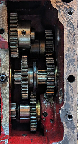
Here, the castellations are disengaged, leaving the 38-tooth gear as an idling gear driven by axis c, but coupling b:c at unity through a pair of 23-tooth gears.

T​

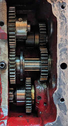
Here, the long 19-tooth gear at the right on axis b engages a 38-tooth gear on axis c.

W/X/Y Selector​

The W/X/Y selector determines which domain, if any, drives the lead screw.

W​

The d domain drives the lead screw

X​

The e domain is disengaged, and the lead screw is not driven

Y​

The b domain drives the lead screw

1-8 Selector​

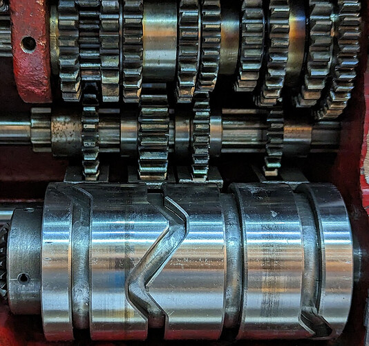
When reassembling the gear box, one of the trickiest bits is to make sure that the number selector is correct.

1​

24:33

2​

27:33

3​

20:22

4​

22:22

5​

23:22

6​

24:22

7​

26:22

8​

28:22

Worked Example​

ATW1 means (input) a→b 20:50 b→c 19:38 c→d 24:33 (feed bar) d→e 36:35 e→f 26:26 (lead screw)

20/50 * 19/38 * 24/33 = 9120/62700 = 456/3135 = 8/55 ~= .1454 (feed bar)

8/55 * 36/35 = 288/1925 ~= .1496 (lead screw)

(Also posted on hobby-machinist at Characterizing the G0709 quick change gearbox | The Hobby-Machinist)
5 Likes

Great post.
Someday there will be a machinist trying to repair/use one of these gearboxes.
And they will find your posts and be flooded with joy and relief that they have some reference material!.
Please give yourself a pat on the back, and thankyou for reminding me about the good people in the world, it’s easy to forget you also exist in this world full of shouting bigots.

3 Likes

Feeds and Speeds

Here’s all the data from the front plate, in mostly-textual form, to use to understand the ratios.

Note that this doesn’t cover the feed rate calculations because it doesn’t include the apron gears and the bed rack pitch. It only covers difference between feed rates.

The lead screw is 8 TPI. The input to the change gears turns 1:1 with the spindle. This should allow exact calculation for all lead-screw-driven pitches.

Change Gears

  • F: 32:76 33:66
  • G: 32:76 66:33
  • H: 32:76 66:42 (Used only for worm cutting, as part of approximating pi

Z Feed (inches)

1 3 6 8
F A T X 0.00168 0.0021 0.00252 0.00294
F A S X 0.00336 0.0042 0.00504 0.00587
F A R X 0.00671 0.00839 0.01007 0.01175
F B R X 0.01679 0.02098 0.02518 0.02937
G B S X 0.03357 0.04196 0.05035 0.05875
G B R X 0.06714 0.08392 0.10071 0.1175

X Feed (inches)

1 3 6 8
F A T X 0.00046 0.00057 0.00069 0.00081
F A S X 0.00092 0.00115 0.00138 0.00162
F A R X 0.00185 0.00231 0.00277 0.00323
F B R X 0.00462 0.00577 0.00692 0.00808
G B S X 0.00923 0.01154 0.01385 0.01615
G B R X 0.01846 0.02307 0.02769 0.03231

mm threads

1 2 3 4 5 6 7 8
F A T W 0.1 0.125 0.25
F A S W 0.2 0.225 0.25 0.3 0.35
F A R W 0.4 0.45 0.5 0.55 0.6 0.65 0.7
F B S W 0.75 0.875
G A S W 0.8 0.9 1.1 1.2 1.3 1.4
F B R W 1 1.25 1.5 1.75
G A R W 1.6 1.8
G B S W 2 2.25 2.5 2.75 3 3.25 3.5
G B R W 4 4.5 5 5.5 5.75 6 6.5 7

Threads/inch

1 2 3 4 5 6 7 8
G C T Y 4 4.5 5 5.5 5.75 6 6.5 7
G C S Y 8 9 10 11 11.5 12 13 14
G B Y 9.5 9.5 9.5 9.5 9.5 9.5 9.5 9.5
F C T Y 16 18 20 22 23 24 26 28
F C S Y 32 36 40 44 46 48 52 56
F B Y 38 38 38 38 38 38 38 38
F C R Y 64 72 80 88 92 96 104 112

Module pitch (metric worms)

1 2 3 4 5 6 7 8
H A T W 0.1 0.125 0.15 0.175
H A S W 0.2 0.225 0.25 0.275 0.2875 0.3 0.325 0.35
H B T W 0.375
H A R W 0.4 0.45 0.5 0.55 0.575 0.6 0.65 0.7
H B S W 0.5625 0.625 0.6875 0.75 0.8125 0.875
H B R W 1 1.125 1.25 1.375 1.5 1.625 1.75

Diametral pitch (inch worms…)

1 2 3 4 5 6 7 8
H C T Y 16 18 20 22 23 24 26 28
H C S Y 32 36 40 44 46 48 52 56
H B Y 38 38 38 38 38 38 38 38
H C R Y 64 72 80 88 92 96 104 112
1 Like

Let’s test this. Before I took apart my gearbox, I had worked out the CSY1 configuration treating the gearbox as a black box.

GCSY1 is the setting for 8tpi, and the leadscrew is 8tpi, therefore it’s one revolution of the lead screw for each revolution of the spindle.

G: 32:76 → 66:33 = 8:19 2:1 = 8/19*2 = 16/19 going into the gearbox. That must mean that CSY1 results in the gearbox providing 19/16.

Start by finding the driving order:

C…Y: a→d→c →b→e→f
Y couples b:e 35:35 (unity) and e:f is permanently coupled 26:26 (unity)

Note that we in general have to pay attention to the order of the couplings for the b, c, and d domains .

  • a:d 19:22
  • d:c 33:24
  • c:b 23:23 = 1:1
  • b:e:f 1:1:1

That gives us 19/22 * 33/24, which reduces to 19/16, which matches the black box.

That gives me some confidence that I might have done this at least partially right! :smiling_face:

1 Like

After doing various tests running the servo on its own at various rates using its diagnostic tool, I determined that geared 6:1 it is able to drive any gear combination in the gearbox, so my earlier expectation that I’d have to use ATW1 was wrong.

I decided to start with ASW8. What is the gearbox doing there?

  • AW ⇒ a→a→c→d(feed)→e→f(lead)
  • ASW8 ⇒
    • a:b 20:50 = 2:5
    • b:c 23:23 = 1:1
    • c:d 28:22 = 14:11
    • d:e 36:35
    • e:f 1:1

2/5 * 14/11 = 28/55 = 28:55 ~= .509 (feed screw)
2/5 * 14/11 * 36/35 = 144/275 = 144:275 ~= .524 (lead screw)

(Checking my simplification, 35/36 ~= .97 and .509/524 ~= .97)

So fed from the servo, that’s
11:66 = 1/6 * 144/275 = 24/275 = 24:275

That’s tooth ratio; of course turns is the inverse.

So for every 275 turns of the servo, the lead screw will turn 24 times.

Now I’d like to calculate feeds. I have not disassembled the apron to count feed gear teeth. But now that I know what is in the gearbox, I should be able to treat the apron gear train as a black box and work out its Z (spindle axis) and X (cross feed) rates.

I’m going to use GBRX8 as the basis of my calculations because it’s the fastest feed.

GBRX8:

  • G: 32:76 66:33 = 8:19 2:1 = 16:19
  • B: a→b→c→d
    • a:b 19:19 = 1:1
    • b:c 38:19
    • c:d 28:22

gearbox alone: (38 * 28) / (19 * 22) = (19 * 2 * 2 * 2 * 7) / (19 * 2 * 11) = (2 * 2 * 7) / 11 = 28 /11
adding change gears: 16:19 28:11 = (16 * 28) / (19 * 11) = 448 / 209

Again, we need the reciprocal to change from teeth to turns; every 209 turns of the spindle drives the feed bar 338 turns, which:

  • Z: moves .1175" per spindle turn, and 209 spindle turns * .1175" per turn = 24.5575" total travel, and 24.5575" / 338 feed bar turns = .072655" per turn of the feed bar.
  • X: moves .03231" per spindle turn, and 209 spindle turns * .03231" = 6.75279" total travel, and 6.75279" / 338 feed bar turns = .019978" per turn of the feed bar.

So now I’ve characterized the X and Z power feed without having to disassemble the apron.

1 Like

I’m really confused. I calculated for ASW8 and tried to cut 4 threads per inch, and got what looked like 10 threads per inch. I measured it with a dial indicator, and indeed it was .1" per spindle turn. Off from my calculations by 2.5:1

There is only one place in the whole system with a 2.5:1 ratio, and that’s the 20:50 which I’ve recorded as the A configuration, next to a 1:1 B configuration. I changed from A to B, and now threading is correct. I don’t understand how the switch lever could possibly work that way. I had hoped that I had completely characterized it without disassembling the gears entirely; now I’m not so sure.

Ok then, that made my head hurt!!!
image

1 Like

Ah. I haven’t yet checked on the lathe, but I just discovered that at one point I had an arithmetic mistake on a sheet of paper that put me off by a factor of 2.5. I admit that I wasn’t keeping a lab notebook so I can’t be sure, but that would explain it working when I shifted from A to B, introducing a completely coincidental correcting factor of 2.5!

I’ve got some evening commitments coming up that mean it might take me a while to get back to this, but I feel more hopeful than I did before finding that mistake.

Yeah, that made my head hurt too.

2 Likes

I wonder where you could find someone with mathematic abilities to check your math? :thinking::wink:

“Can you help me check my math” was in fact the route to finding the mistake. :grin:

2 Likes

Once I finally got back to my project with correct arithmetic, everything worked correctly, confirming my characterization of the gear ratios. :tada:

3 Likes