A few years ago, in a craigslist accident, I acquired a ¾ ton 14x40 floor-standing Grizzly G0709 lathe. (This was a larger step up from a Harbor Freight mini-lathe than I intended when I idly put a craigslist watch on the word “lathe” in my area…)
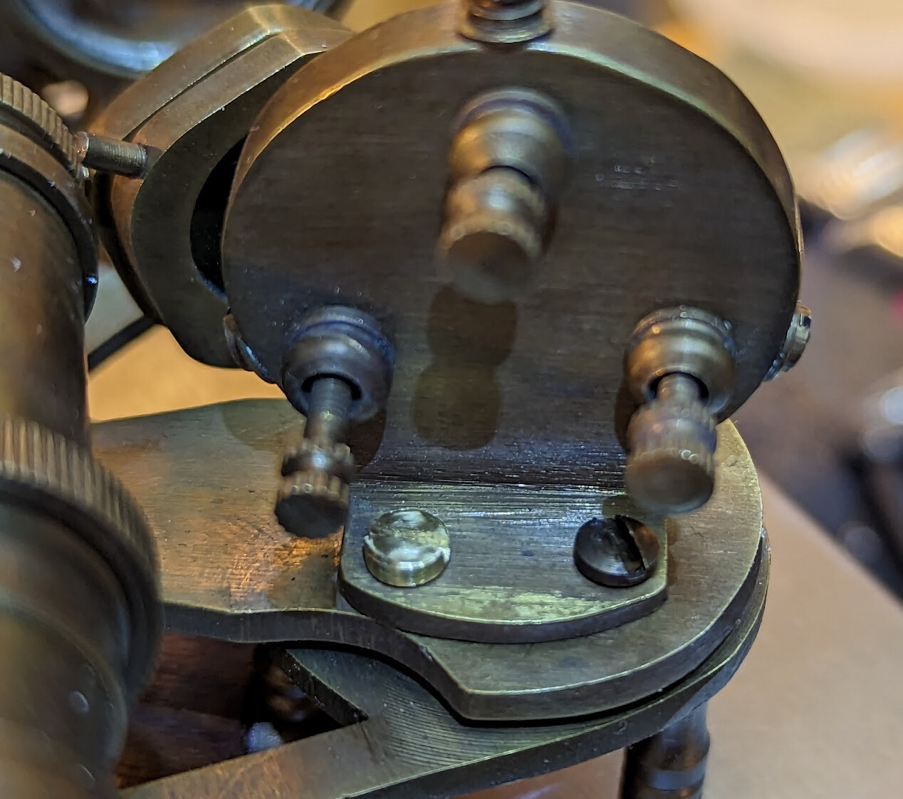
At the beginning of April, in order to repair a sextant, I cut a ridiculously small #4-48 screw on that lathe. About ⅛" of thread on it. Cutting the thread fully but not going too far was annoying. I had idly pondered an electronic lead screw before, but this experience pushed me over the edge.
While the clough42 ELS doesn’t support thread-to-shoulder, Steve Ward (kwackers) has enhanced it to support thread-to-shoulder, angular position reporting, and arbitrary metric thread spec. Therefore, I pulled the trigger, and ordered the initial parts:
- Combo Interface and Control Panel Kit
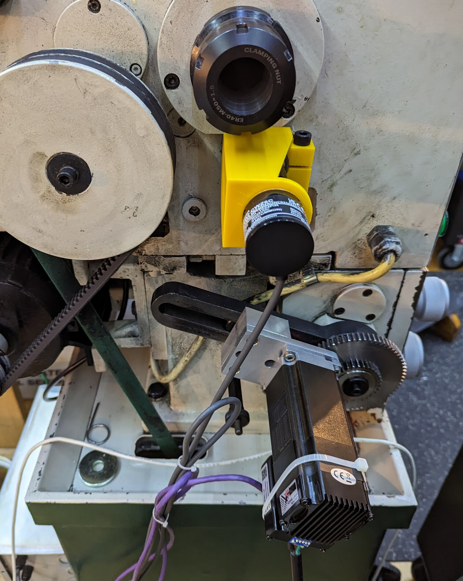
- Omron 1024 count encoder
- TI dev board (and I wish I’d known at the time that James was no longer including the flash chip on his interface boards, or I would have bought a compatible flash chip as well)
- iSV57T-180S servo motor — though if I were doing this again I would probably splurge and go for the substantially more powerful iSV2-80TR-48V750A because it turns out the transmission on my lathe takes some power to move, and I had to choose a gear ratio carefully for the 180W motor to work. A 750W motor would solve that problem, given also a more substantial power supply.
- 36V, 400W DC power supply. The motor is rated for 48 but James’s motor controller broke after about a year, and he was running it at 48V, so I decided to try being conservative, giving it more headroom to avoid back-EMF frying it.
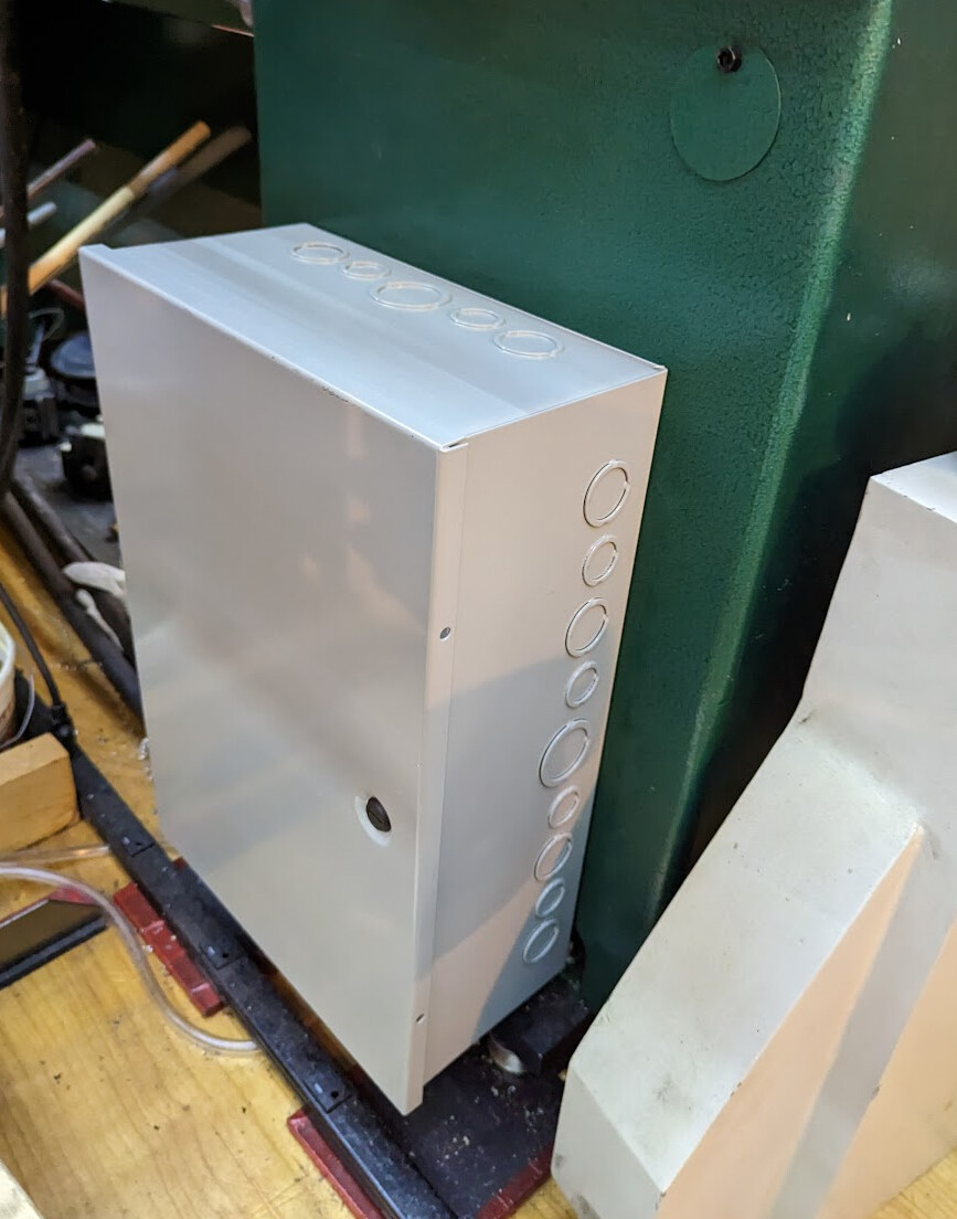
- Hammond CHKO18126 enclosure
I decided that “my shop, my rules” — I almost always run my lathe with the gear door removed. That area isn’t accessible to fall into in my shop, and I can’t use my ER40 spider with the cover on. The transmission settings tables are on the cover, but I won’t need that any more with an electronic lead screw. This meant that I could design for the encoder and motor to stick out, rather than trying to tuck them into place under the cover. (If this were in a shared shop, I’d cut out parts of that cover and let the motor and encoder stick through, in order to keep the belt covered.)
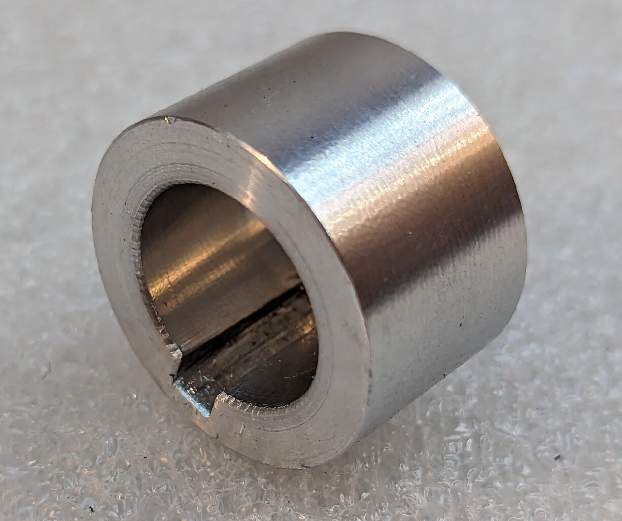
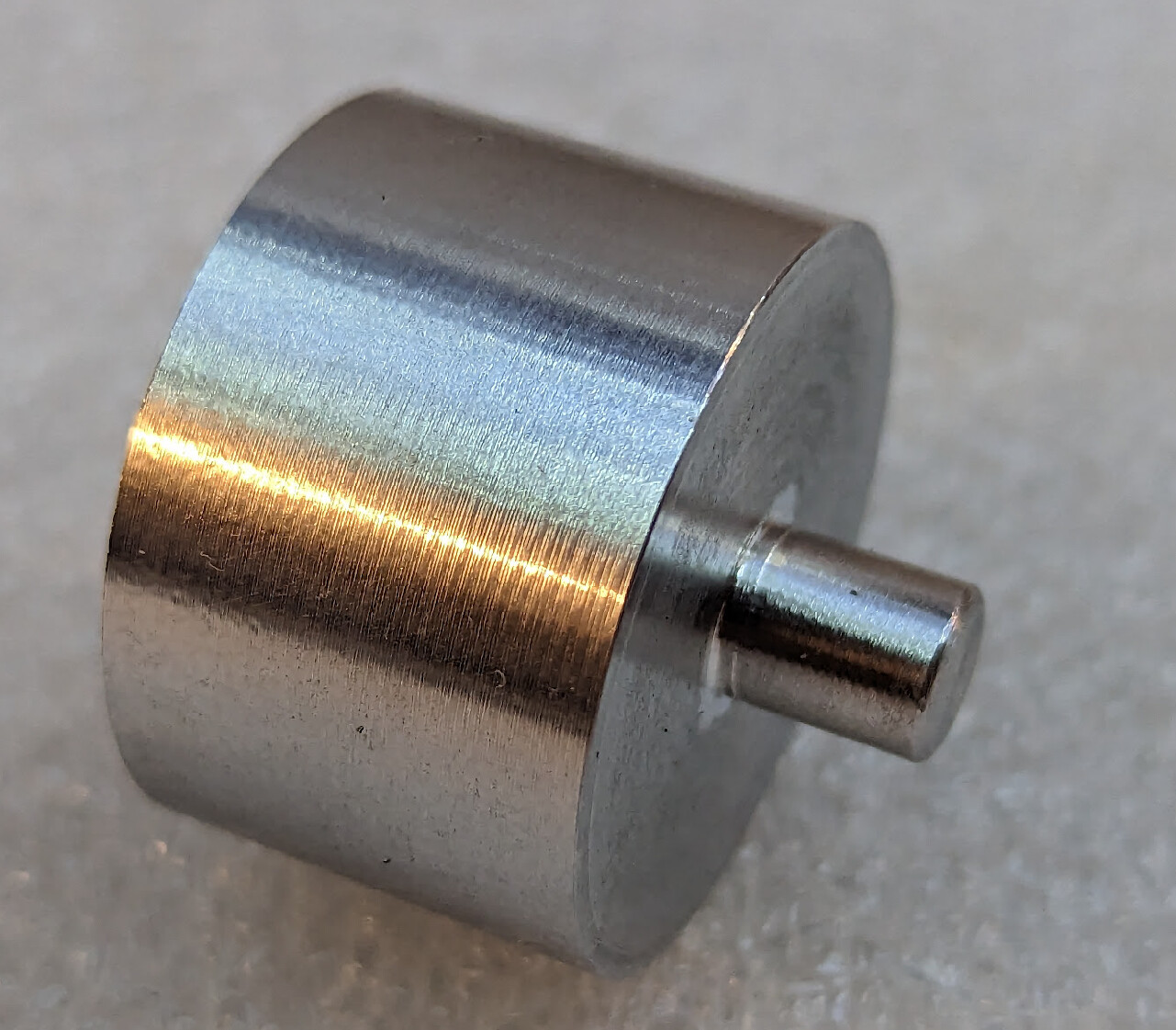
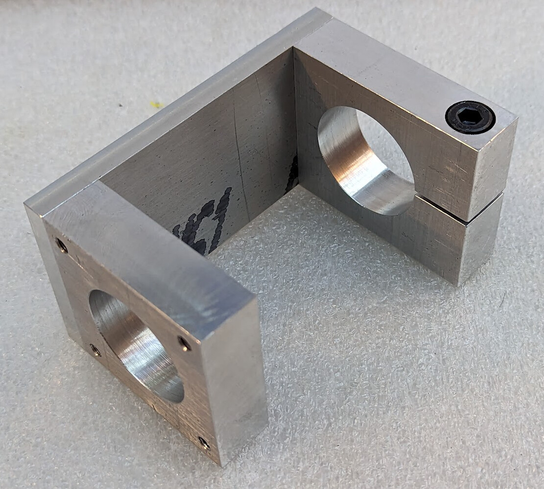
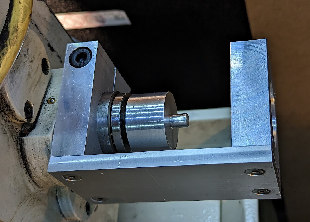
I determined that the change gears were driven from a shaft that turned 1:1 with the spindle, and designed a 3d printed bracket and a coupler. I turned the coupler from a piece of POM, but if I were doing it again, I would just 3D print it with 100% infill in PETG or ABS, and then turn it to dimension on the lathe to ensure concentricity. My initial design was for a bracket that I’d make on the mill from aluminum, but I see no reason to go back and do that again.
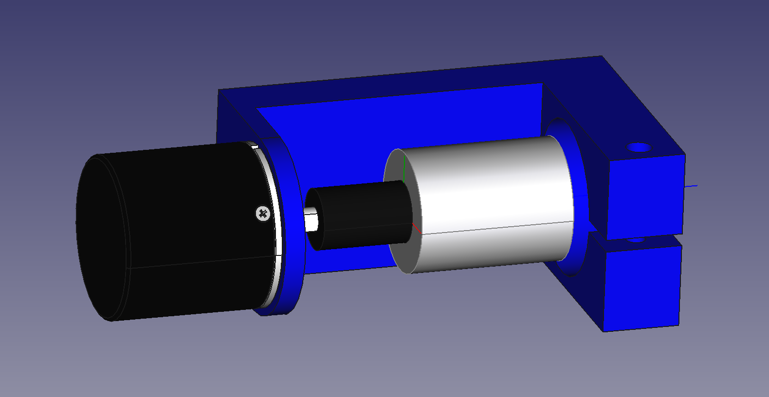
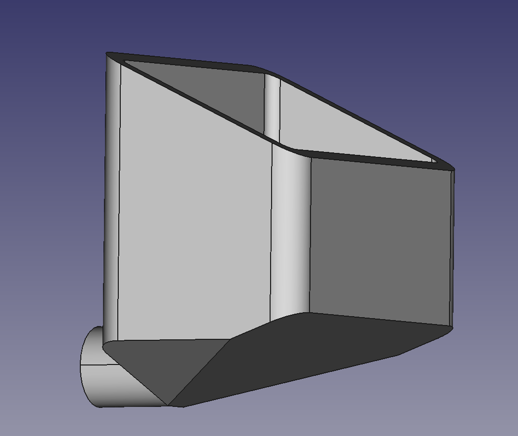
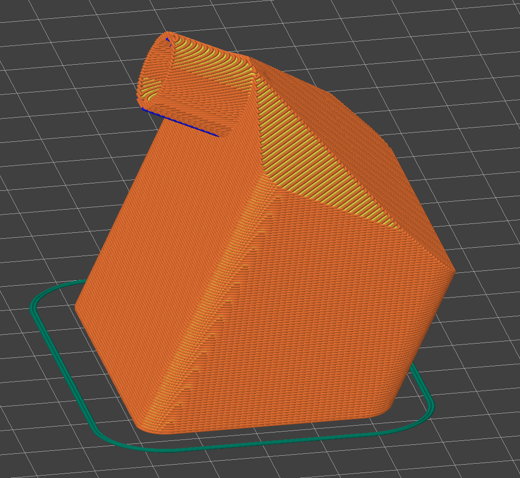
I took feedback on Mastodon and added sides to make it rigid for printing instead of making it out of aluminum:
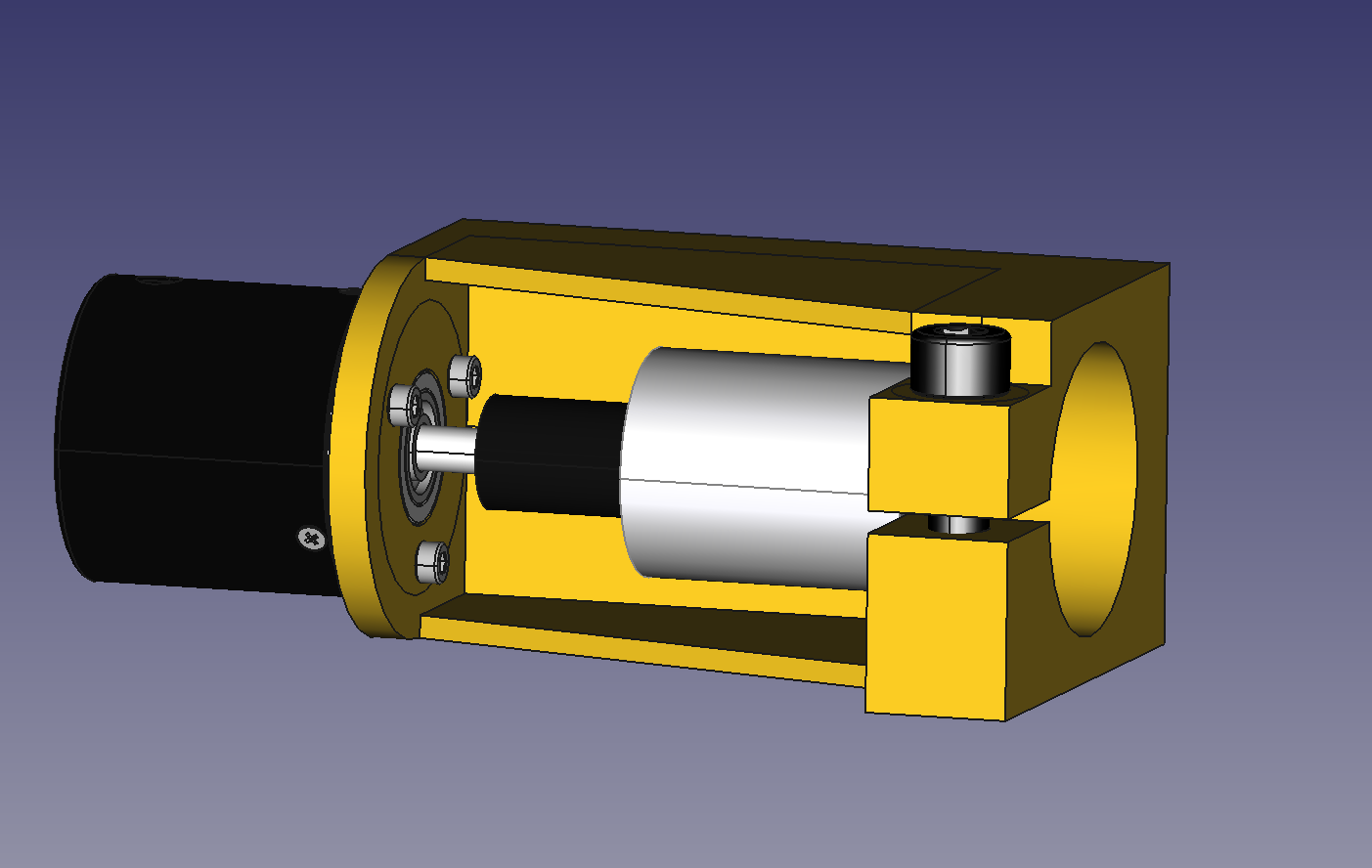
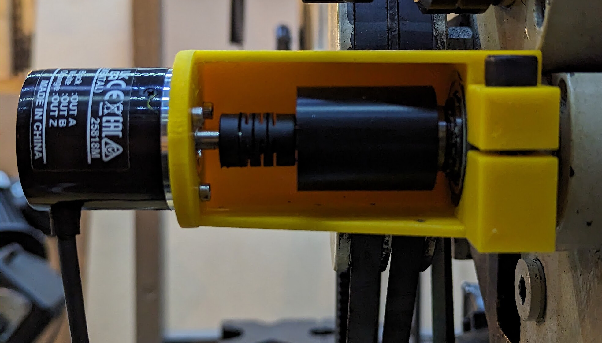
Printed, it looks pretty much like the model!
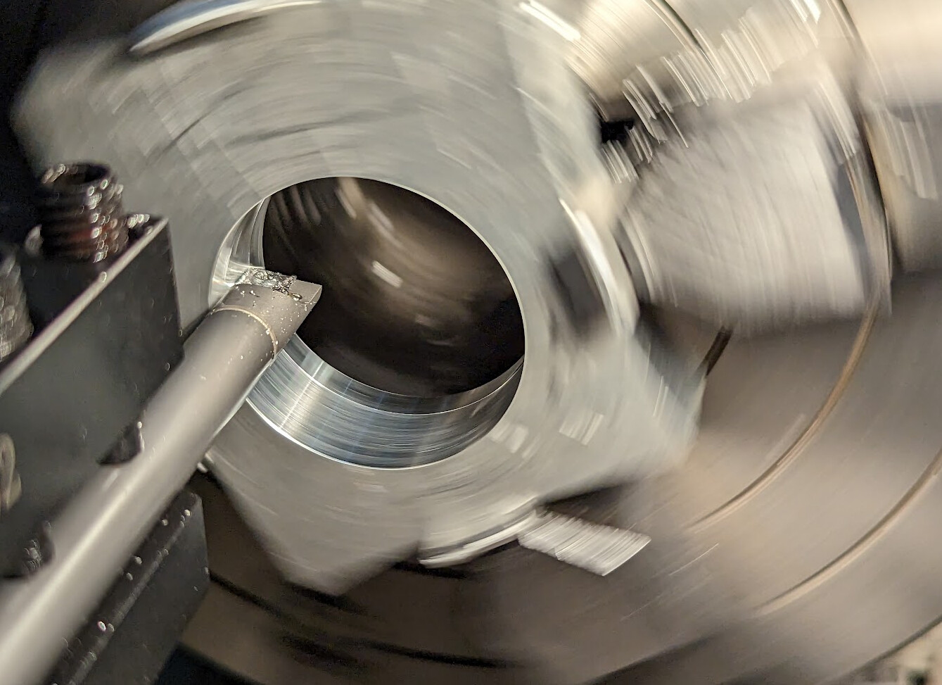
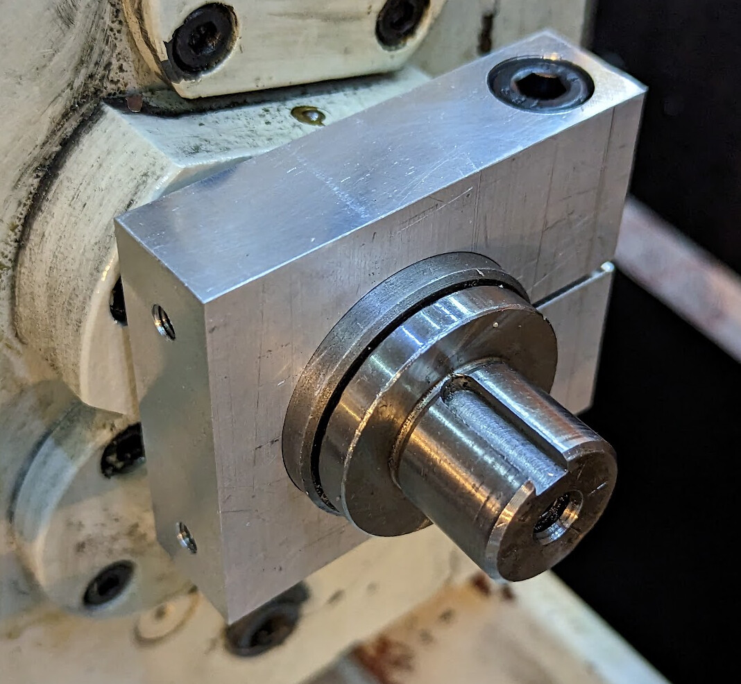
Pleased with myself, I used my Keyway Cutter design and project to cut a 5mm slot in an aluminum coupler to connect the servo motor to the input of the transmission. (That’s how I discovered that the keyway cutter has some design flaws. But I digress) In retrospect, this, like the encoder coupler, ought to have been 3d printed and just finished on the lathe if necessary. But I didn’t really understand yet how weak a 180W motor is. (Foreshadowing!)
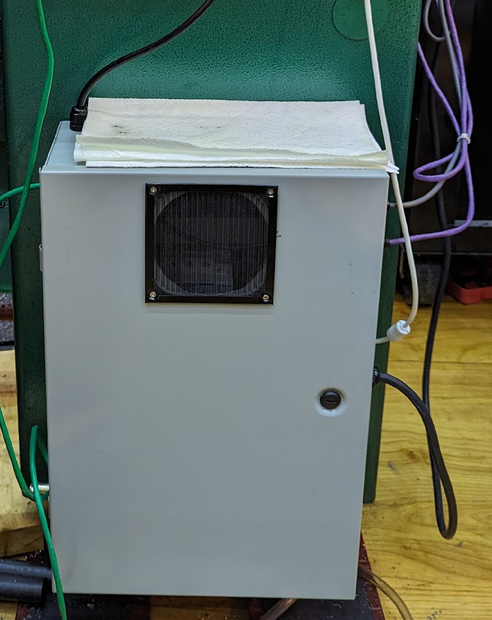
Meanwhile, I’d also bought a lot of electronic components and laid them out in the enclosure. Like James, I put a fan in the bottom and an outlet in the door near the top. Also like James, I also put in some hardware to control a toolpost grinder (which I plan to build later).
I interpreted this:
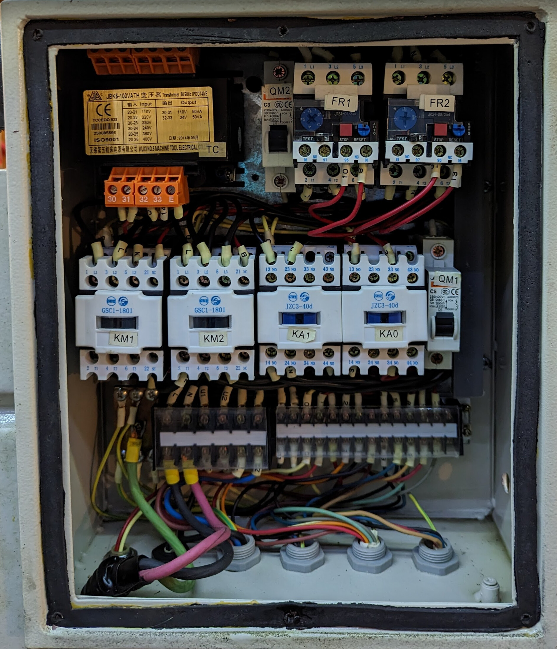
…by means of this:
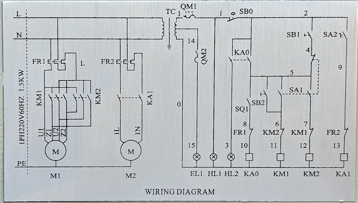
…and worked out how to control my new circuitry from the existing controls. Ultimately I ended up with this:
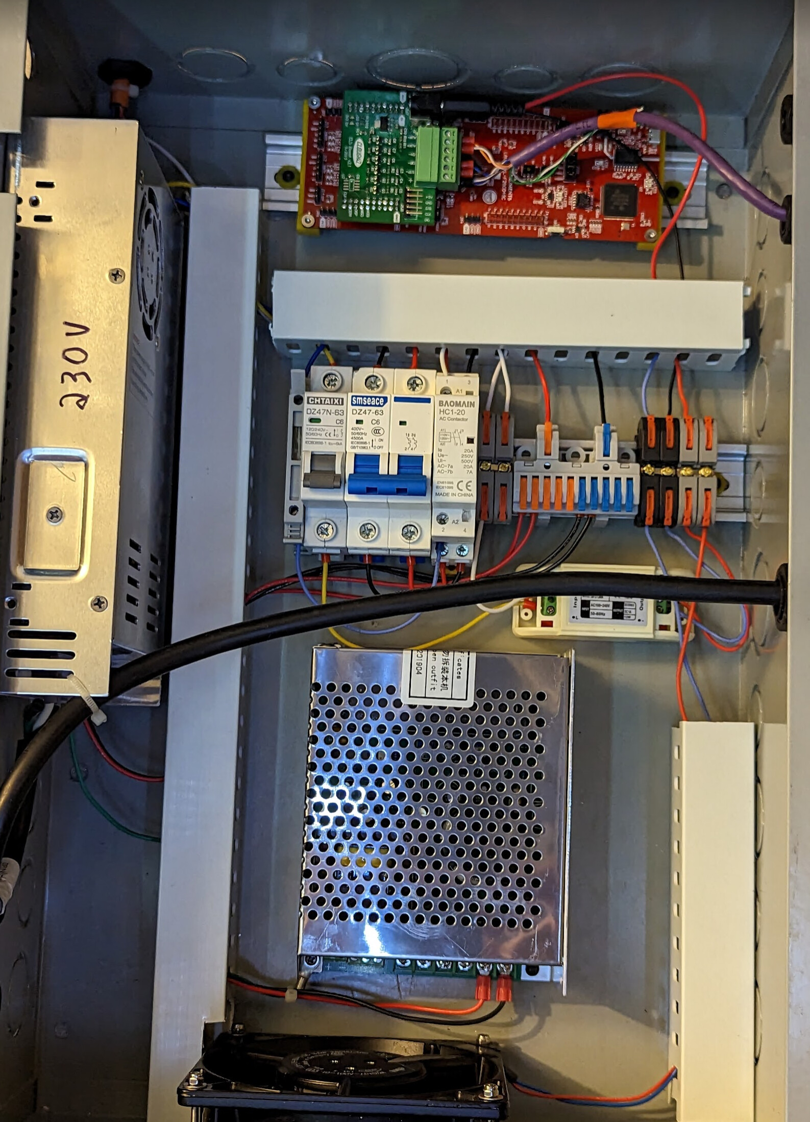
120V from the lathe goes through a fuse to a 120V-12V step-down, which then feeds a 12V-5V buck converter, which powers the dev board at the top. 240V goes through a circuit breaker, then a contactor (which is controlled from net 10 in the diagram above) connects to the 36V servo power supply. (In the end, @chaseadam came over and helped me find the right net for the contactor; it took one person at the lathe controls and another with a multimeter behind the box to identify for sure which net would energize only when the lathe is enabled. I had previously tried net 4, not realizing it was pulled low in operation.)
This does mean that hitting the foot brake turns off power to the lead screw servo! I’m hoping that’s a feature not a bug. It will be safer but will lose sync. The place where I might use the brake in normal operation is threading to a shoulder, but doing that instead under software control and not using the brake was why I started this whole project in the first place!
At this point in the project, I could try using the lead screw. It had seemed easy to just use a transmission setting that would give me 8 threads per inch on my 8-tpi lead screw; that would let me easily calculate travel. However, I ran into two problems.
- In the 8tpi mode, the feed bar didn’t turn
- In modes that would turn the feed bar, the motor would trip its overcurrent protection and need to be reset.
This sent me down several rabbit holes.
- Could I make it turn smoother by cleaning the transmission, not just pouring oil through it?
- Could I remove the transmission entirely and put a new box containing the servo motor in its place?
- What actually were all the gear ratios inside that black box?
- How many teeth should be on a power transmission gear, anyway?
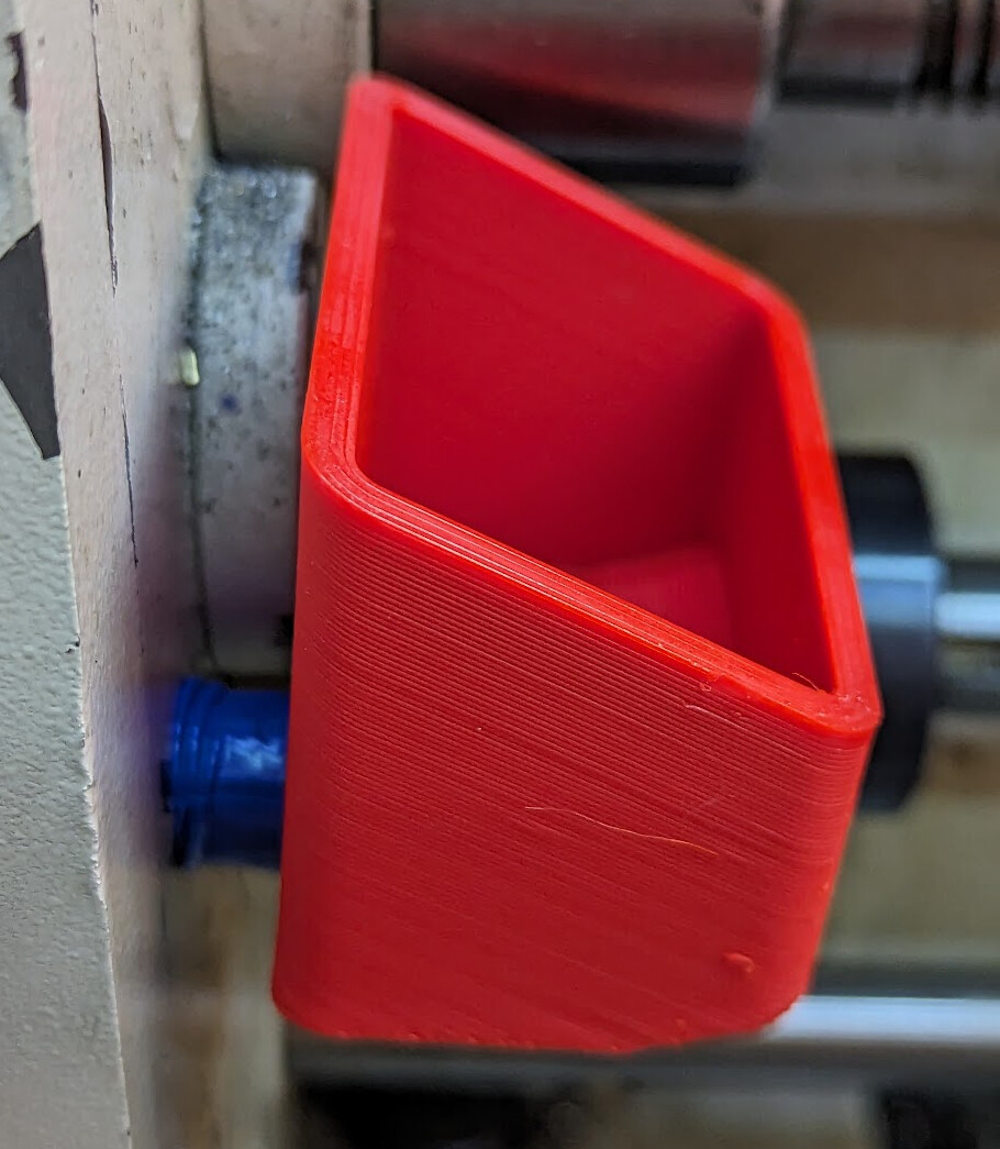
I drained the transmission oil, opened up the case, cleaned out the sludge (some of which seemed to be factory-installed), added magnets for chip-catchers, and spent a few hours sliding gears around and cross-checking the parts list (very complete! Well done Griz!), eventually fully Characterizing the quick change gearbox on my G0709 lathe and understanding what all the ratios were. (In the process of putting it back together, I discovered that trying to use Permatex black to make a gasket was a bad idea after two different tries. This alone took a few weeks of experimentation…) I bought a new gasket from Griz just to be sure and buttoned it back up. Then I 3d printed a custom funnel to get oil back in through the side, which worked great, and now is part of the lathe tools set. ![]()
It became clear while working on the transmission that building a replacement with direct drive was too deep a rabbit hole. It is possible, and it might be a fun project on the mill someday, but it was not necessary. It’s a bit silly to turn all those gears just to leave them in one configuration forever, but for now this is how it’s going to be.
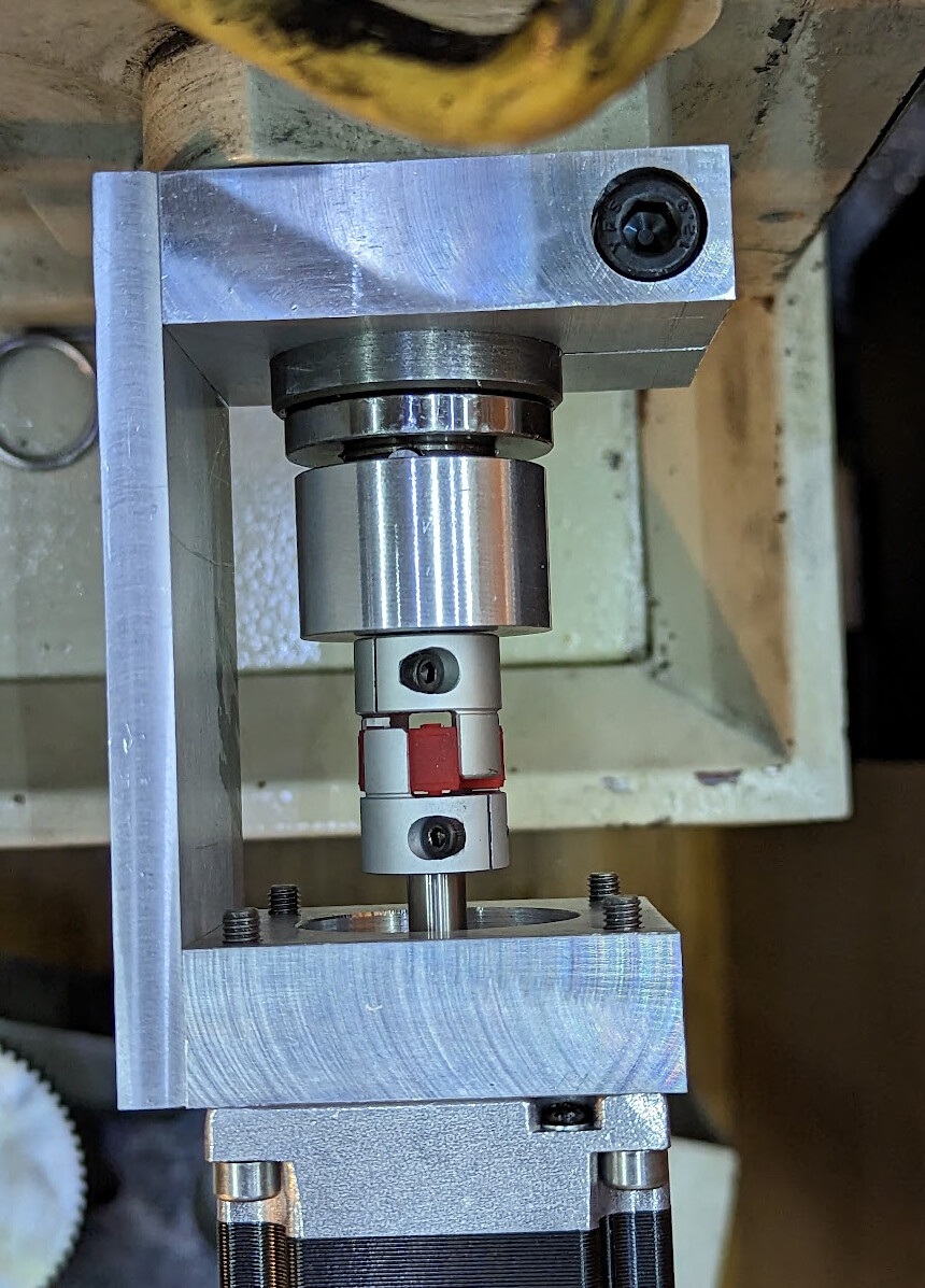
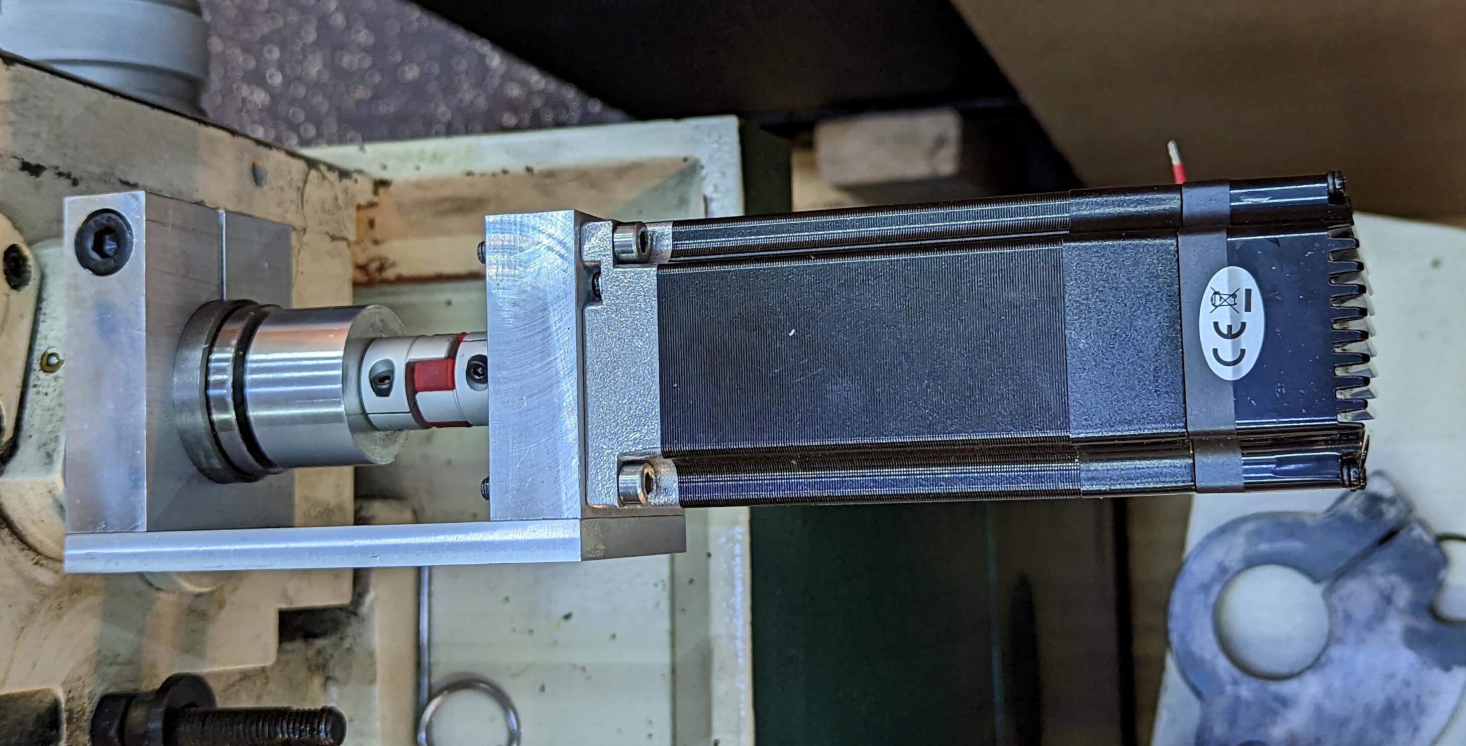
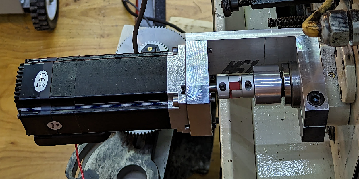
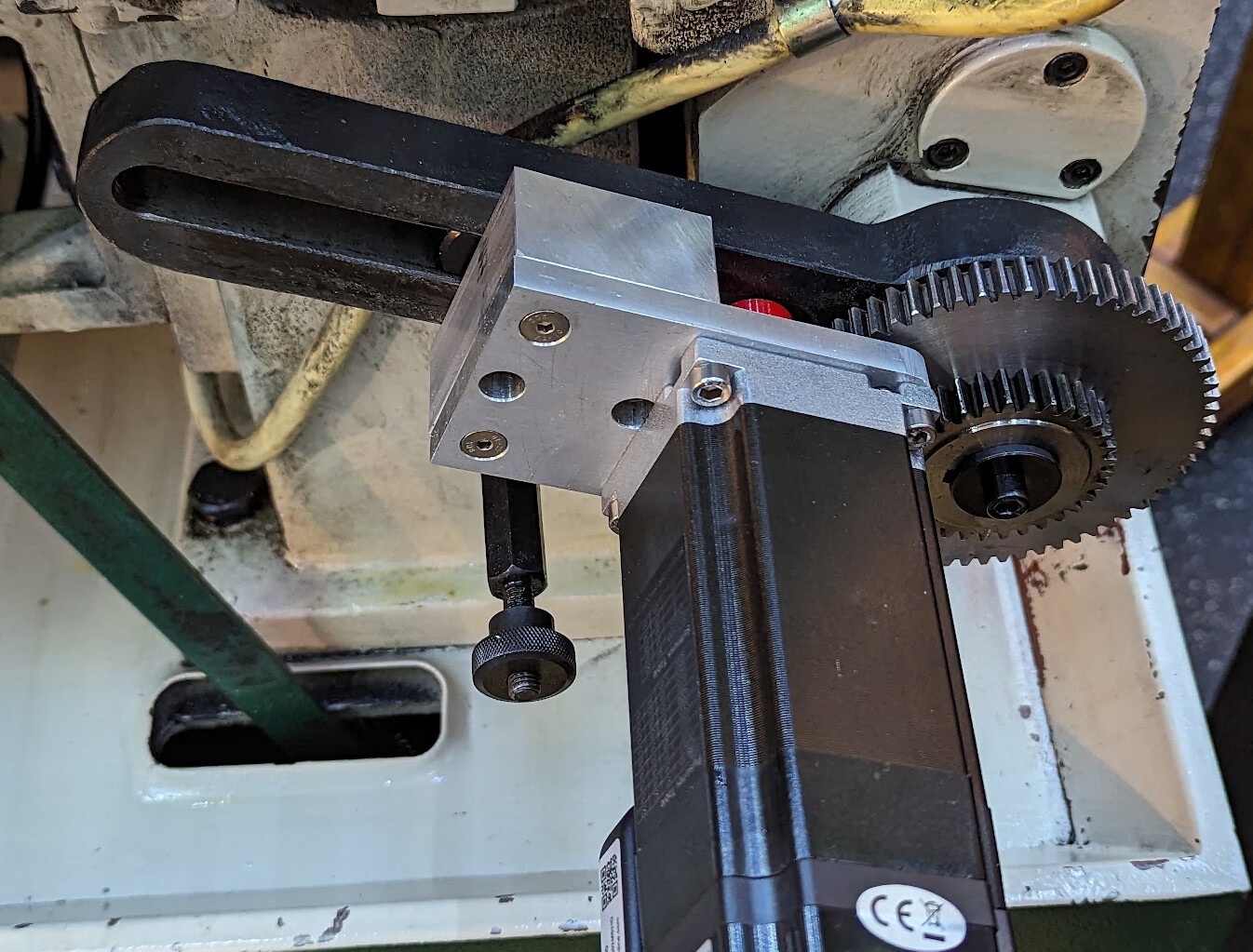
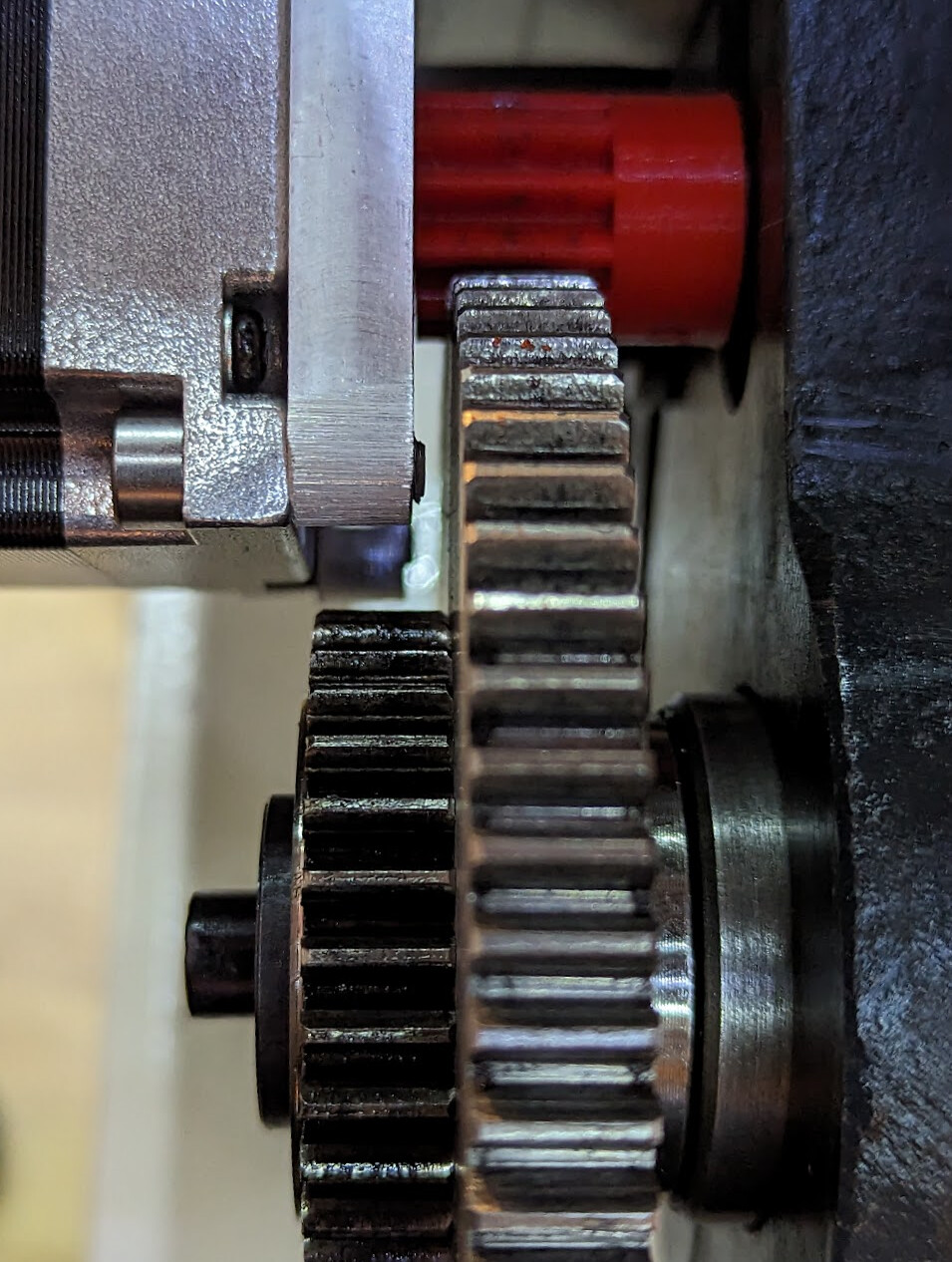
Instead of running the input 1:1, I chose a configuration that had high mechanical advantage and drove both the lead screw and the feed bar, and then added advantage by driving it through another 6:1 reduction by putting the 66-tooth gear on the transmission input shaft, and an 11-tooth gear, with a prototype 3d printed in PETG on the servo.
I used part of the old motor bracket to make a new bracket to mount the motor on the original banjo, using the original t-nuts, to engage the new prototype gear with the 66-tooth change gear on the input. (I have another gear mounted there just as a spacer; I could turn a simple spacer if I want but why bother?)
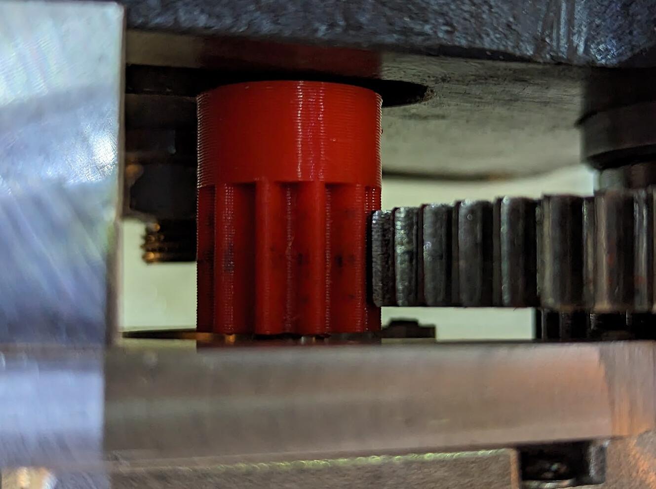
I bought some 1.5 module cutters so that I could cut a metal final gear after using the PETG gear as the prototype, but the servo feeds back when not connected and when connected 1:1, but doesn’t feed back when connected through the PETG gear. So even though I finally worked out how to cut an 11-tooth gear with a 12-tooth cutter, I plan to stick with PETG now, and just re-print gears from time to time. Or I could print them from nylon, or machine them from POM or nylon. But I think plastic wear parts here are actually a feature not a bug.
I had some trouble getting it to cut the right pitch. I made a simple arithmetic error on paper. Ironically, I got it right when writing about it on the computer, but when I went to compute the actual ratios to use, I started from the paper with a mistake. The funny thing was that the mistake completely by change was exactly offset by choosing a different transmission setting, which was quite the red herring. I thought I had failed to correctly characterize the gears. But my favorite mathematician checked my work and pointed out the mistake.
After validating threading by turning the lathe chuck by hand (in angular position reporting mode) while measuring travel over an inch with a dial indicator, I was able to measure the corresponding Z (towards the spindle) feed rate also by measuring travel, and configure the firmware for it. Sadly, I can’t separately display X feed, but the exact amount doesn’t matter very much, and it’s about ¼ the speed of the Z feed. I’m not even sure how the display could show Z and X feed rates, honestly.
With all that done, everything I’ve tried so far is working! I removed the USB cables from the dev board and the servo motor, closed the cabinet, and called it a day.
Now I can finally thread to a shoulder. I was not expecting this project to take (on and off, I’ve been busy) five months.
Want to join me?
I have shared my software configuration in a draft pull request so that others can build on it, possibly using it exactly as is for the G0709, or possibly using it as a pattern for some other lathe that isn’t as simple as just hooking up 3:1 or 6:1 or something like that directly to the lead screw, as is reasonably common on some smaller lathes.
Also, the G0709 is capable of cutting a lot more threads than James set up in his project. In fact, some of the threads it cuts cannot be added to the thread tables that James included because the tables don’t have sufficient precision. But then his table has threads already that the G0709 can’t cut; for example 27TPI was not supported by the change gears and transmission that came with the lathe, but what James originally wrote does include 27TPI. Included in my G0709 support PR, but also available on its own, is a PR for James which adds a digit of precision and optionally adds more threads (as it happens, all the threads that my lathe can cut but his original version can’t).
Thanks to @craftyjon@chaos.social, maybe I’m not quite done, because I’d like to use QElectroTech to make a circuit diagram, both to install inside the enclosure, and to post here as documentation.
This version of the story leaves out some of the wrong turns, especially the ones that aren’t particularly educational, and rearranges the timeline a little to be easier to follow, I hope. If you follow me on mastodon, you got more of the play-by-play tagged #electronicLeadScrew.